


由于项目的需求,所以最近一直再研究204B协议;通过这一段时间的接触和了解,终于理解了204B协议中的Code group synchronization的概念;与大家分享一下,如果有错误的地方,欢迎指正。
假设FPGA与ADC数据采集芯片的应用场景如下图所示,FPGA与ADC之间使用2个lanes的serdes串行总线传输数据;假设ADC芯片内部集成了4个用于采集模拟数据的ADC。
FPGA与ADC芯片之间,用于传输数据的串行协议就是204B;204B协议再传输数据之前,需要完成一个步骤,即Code group synchronization。在这里,我把它翻译为“编码组同步操作”。

通道的Code group synchronization编码组同步过程,是通过以下过程实现的(先把204B协议的描述搬过来,见下边4条英文描述)。
• The receivers issue a synchronization request via the synchronization interface.
• The transmitters emit a stream of /K/= /K28.5/ symbols.
• The receivers synchronize, and then wait for the correct reception of at least four consecutive /K/symbols.
• The receivers deactivate the synchronization request in accordance with the guidelines outlined in 7.1.
204B包括subclass0、subclass1、subclass2,共3种应用模式;subclass0为了兼容204A协议,不支持确定延时;subclass1、subclass2是204B协议特有的模式,主要目的是支持deterministic delay,即确定的延时;
子类0应实现以下行:
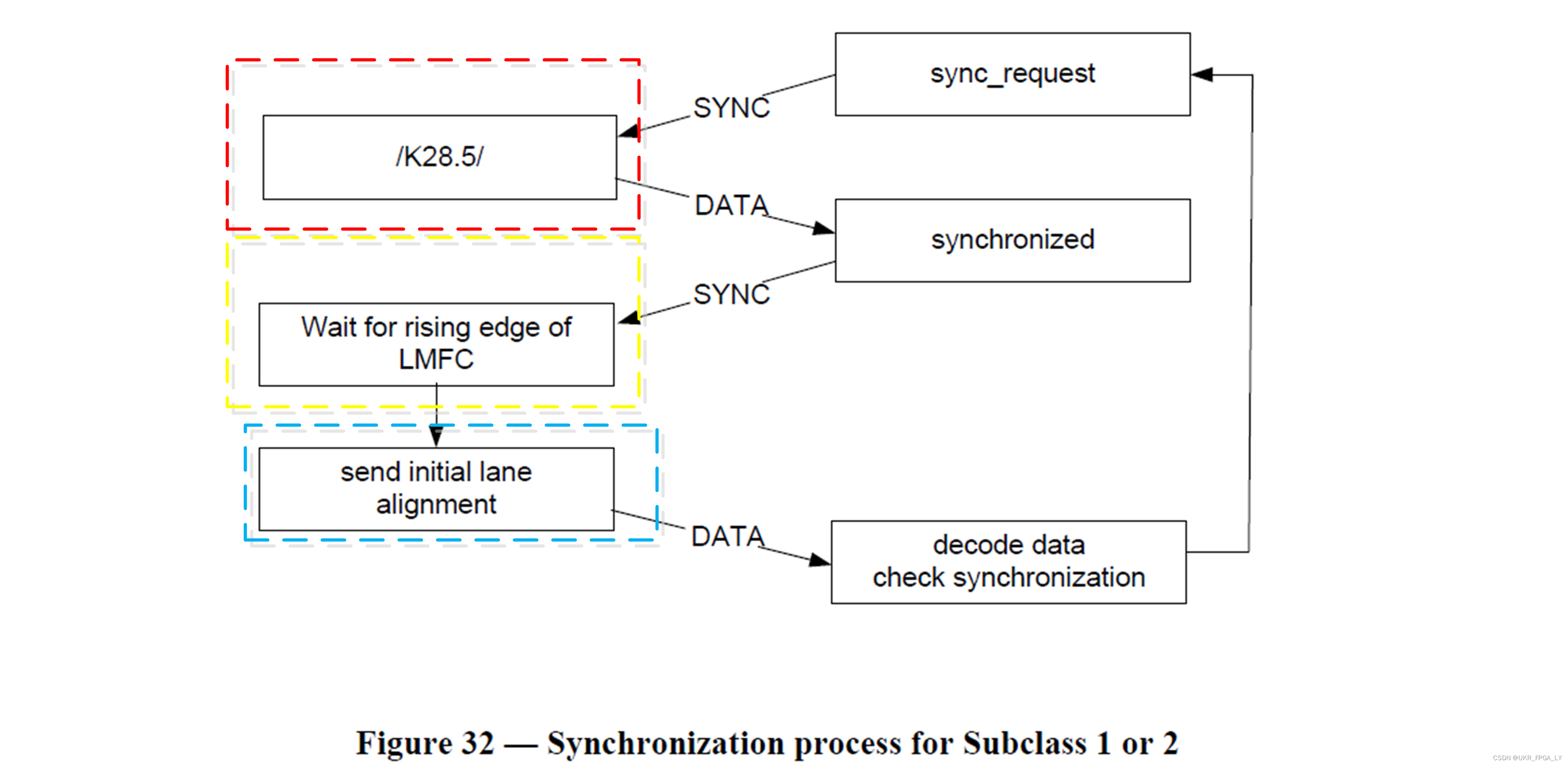
The synchronization process is shown in the flow diagrams of the following figures. The ‘SYNC’ transitions indicate a change of state in the SYNC~ signal generated by the RX. The ‘DATA’ transitions indicate a change of state in the data generated by the TX.

我理解的时序:
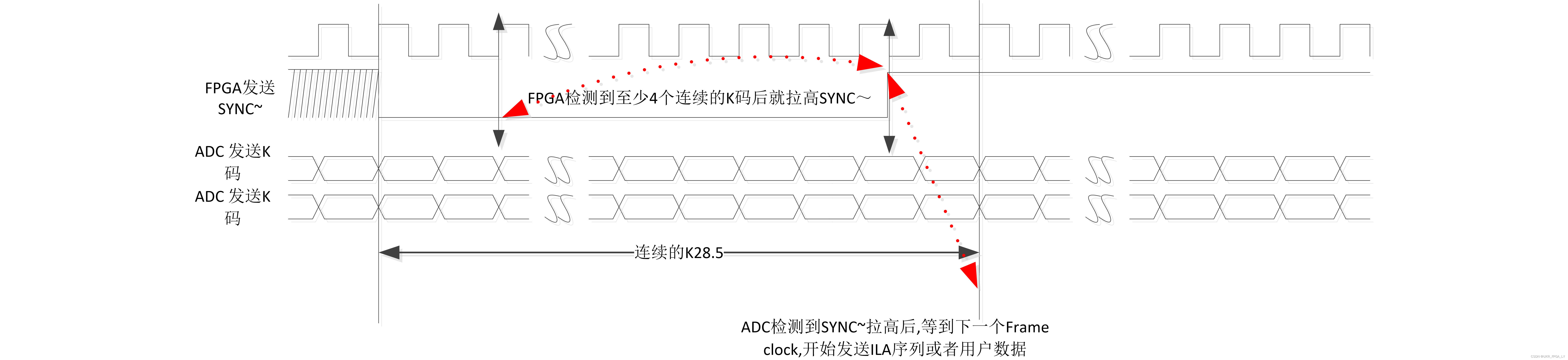
• FPGA(也就是Receiver)通过SYNC~信号向ADC(也就是Transmitter)发起同步请求;
• ADC检测到SYNC~信号后,开始发送K28.5序列;
• FPGA所有通道都检测到4个连续的K28.5后,拉低SYNC~;
• ADC检测到FPGA已停止SYNC信号请求后,ADC将继续发射 /K/ 符号,直到下一帧开始。
• 从下一帧开始,ADC发出初始通道对齐序列 (ILA) 或编码的用户数据。
子类1和子类2应实现以下行:
The synchronization process is shown in the flow diagrams of the following two figures. The ‘SYNC’ transitions indicate a change of state in the SYNC~ signal generated by the RX. The ‘DATA’ transitions indicate a change of state in the data generated by the TX.
我理解的时序:
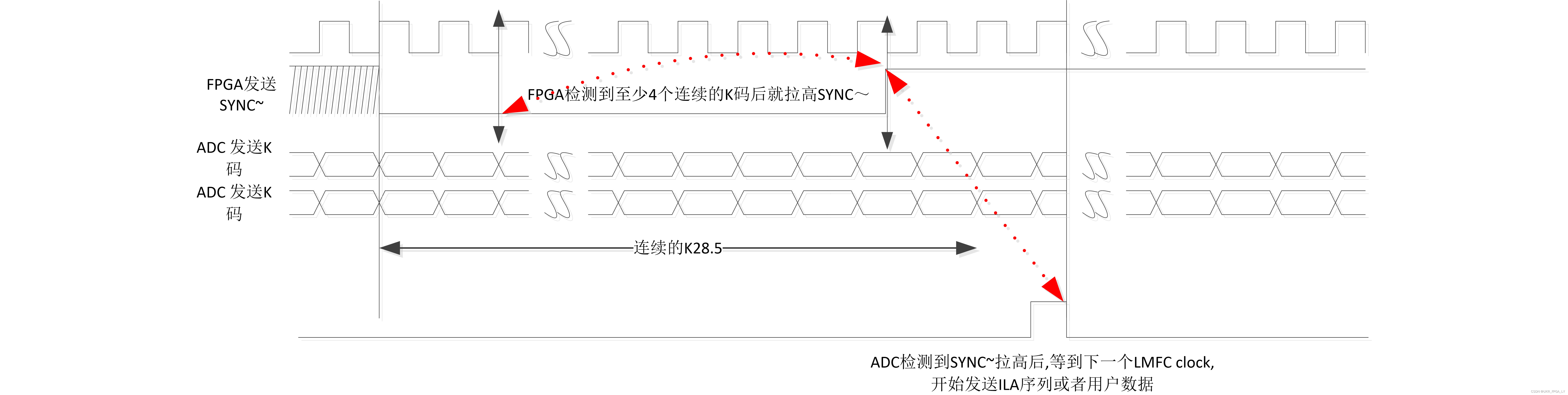
• FPGA(也就是Receiver)通过SYNC~信号向ADC(也就是Transmitter)发起同步请求;
• ADC检测到SYNC~信号后,开始发送K28.5序列;
• FPGA所有通道都检测到4个连续的K28.5后,拉低SYNC~;
• ADC检测到FPGA已停止SYNC信号请求后,ADC将继续发射 /K/ 符号,直到下一个LMFC开始。
• 从下一个LMFC开始,ADC发出初始通道对齐序列 (ILA) 或编码的用户数据。
总结
Code group synchronization概念是针对单个Lane的,目的是使RX从接收到的bit流中识别出K码(识别K码之前要恢复时钟等)。识别到K码后,也就找到了8B/10B编码后的symbol,为后续ILA序列的识别和lane对齐做准备。


 1117
1117


 被折叠的 条评论
为什么被折叠?
被折叠的 条评论
为什么被折叠?
 到【灌水乐园】发言


