


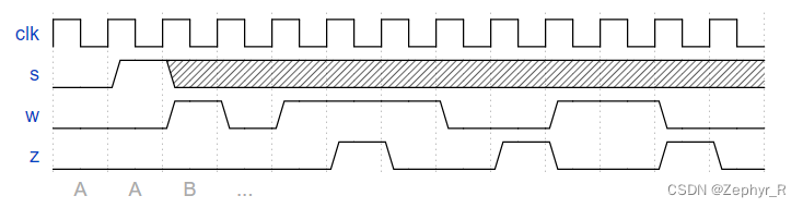
Consider a finite state machine with inputs s and w. Assume that the FSM begins in a reset state called A, as depicted below. The FSM remains in state A as long as s = 0, and it moves to state B when s = 1. Once in state B the FSM examines the value of the input w in the next three clock cycles. If w = 1 in exactly two of these clock cycles, then the FSM has to set an output z to 1 in the following clock cycle. Otherwise z has to be 0. The FSM continues checking w for the next three clock cycles, and so on. The timing diagram below illustrates the required values of z for different values of w.
Use as few states as possible. Note that the s input is used only in state A, so you need to consider just the w input.

module top_module (
    input clk,
    input reset,   // Synchronous reset
    input s,
    input w,
    output z
);
    reg[2:0] state,next_state;
    reg[1:0] count;
    parameter A=0,B_1=1,B_2=2,B_3=3,B_z=4;

    wire en_count;
    wire en_z;

    always@(posedge clk) //状态转移
    begin
      if(reset)
       begin
        state <= A;
        count <= 0;
       end
      else
       begin
        state <= next_state;
        if(state==B_3) count <= 0;
        else if (en_count) count <= count+1;
       end
    end

    always @(*)
    begin en_count=0; //初始化防止latch
    case(state)
    A: next_state = (s ? B_1:A);
    B_1: begin next_state = B_2; en_count=(w ? 1:0); end  //B_1状态为第一个技术状态,并且不输出Z
    B_2: begin next_state = B_3; en_count=(w ? 1:0); end
    B_3: begin next_state = (en_z ? B_z:B_1);        end  //三次计数后是否输出Z由en_z信号控制,并且重置计数器
    B_z: begin next_state = B_2; en_count=(w ? 1:0); end  //B_z状态为输出Z并且重新开始计数
    endcase
    end

    assign en_z = ((count==1) & w)|((count==2) & ~w); //当前两个状态有一个w,并且B_3为W 或者 前两状态w都为1且B_3W为0时 进入B_z状态
    assign z = (state==B_z);
endmodule


 1633
1633


 被折叠的 条评论
为什么被折叠?
被折叠的 条评论
为什么被折叠?
 到【灌水乐园】发言


