


Given the following state machine with 3 inputs, 3 outputs, and 10 states:
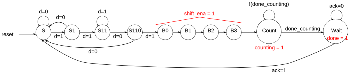
Derive next-state logic equations and output logic equations by inspection assuming the following one-hot encoding is used: (S, S1, S11, S110, B0, B1, B2, B3, Count, Wait) = (10'b0000000001, 10'b0000000010, 10'b0000000100, ... , 10'b1000000000)
Derive state transition and output logic equations by inspection assuming a one-hot encoding. Implement only the state transition logic and output logic (the combinational logic portion) for this state machine. (The testbench will test with non-one hot inputs to make sure you're not trying to do something more complicated. See fsm3onehot for a description of what is meant by deriving logic equations "by inspection" for one-hot state machines.)
Write code that generates the following equations:
- B3_next -- next-state logic for state B3
- S_next
- S1_next
- Count_next
- Wait_next
- done -- output logic
- counting
- shift_ena
-
module top_module(
    input d,
    input done_counting,
    input ack,
    input [9:0] state,    // 10-bit one-hot current state
    output B3_next,
    output S_next,
    output S1_next,
    output Count_next,
    output Wait_next,
    output done,
    output counting,
    output shift_ena
); //
    wire S11_next,S110_next,B0_next,B1_next,B2_next;
    // You may use these parameters to access state bits using e.g., state[B2] instead of state[6].
    parameter S=0, S1=1, S11=2, S110=3, B0=4, B1=5, B2=6, B3=7, Count=8, Wait=9;

     assign S_next = (state[S] & ~d)|(state[S1] & ~d)|(state[S110] & ~d)|(state[Wait] & ack);
     assign S1_next= (state[S] & d);
     assign S11_next =(state[S1] & d)|(state[S11] & d);
     assign S110_next = (state[S11] & ~d);
     assign B0_next = state[S110] & d;
     assign B1_next = state[B0];
     assign B2_next = state[B1];
     assign B3_next = state[B2];
     assign Count_next = (state[B3])|(state[Count] & ~done_counting);
     assign Wait_next = (state[Count] & done_counting)|(state[Wait] & ~ack);

     assign shift_ena = state[B0]|state[B1]|state[B2]|state[B3];
     assign counting = state[Count];
     assign done = state[Wait];

endmodule


 742
742


 被折叠的 条评论
为什么被折叠?
被折叠的 条评论
为什么被折叠?
 到【灌水乐园】发言


