


与其用华丽的外衣装饰自己,不如用知识武装自己 –马克思
一、designware pcie产品:
- Dual Mode core
- RC core
- EP core
- Switch core
二、架构:
- Common Xpress Port Logic (CXPL)
实现大部分的传输层逻辑,所有的数据链路层逻辑,物理层的MAC部分(包括LTSSM)。这个module就是所说的core。
XADM和RADM都是针对传输应用添加的模块。比如说添加传输队列,仲裁TLP transmmision。 - Transmit Application-Dependent Module (XADM)
- Receive Application-Dependent Module (RADM)
- Configuration-Dependent Module (CDM)
- Power Management Controller (PMC)
- Local Bus Controller (LBC)
- Message Generation (MSG_GEN)
- Hot Plug Control (hotplug_ctrl)
三、核心(CXPL)操作
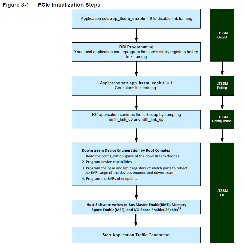
3.1 DM/RC/EP 模式下的初始化
在reset之后,通过检测device_type输入进入到RC或者EP模式,CDM内部配置寄存器为复位值。
LTSSM前配置:keep the app_ltssm_enable signal deasserted after reset until the application is ready to establish a Link and start receiving and transmitting TLPs,在这个阶段通过DBI配置好配置寄存器。
开始LTSSM:assert app_ltssm_enable to allow the LTSSM to begin Link establishment
3.2 Link Establishment
PIPE口,和usb3.0一样。建立链路后,Data Link module发起flow control initialization,完成后通知transaction layer module可以发送接收TLP。
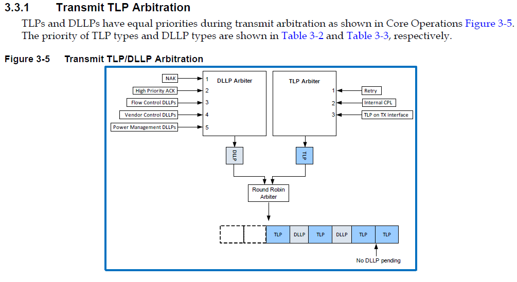
3.3 TLP processing
3.4 Interrupt
支持传统中断intr和MSI
3.5 Flow Control
分为两个phase:初始化和更新。VC0的初始化跟着Link初始化,在发起正常传输之前完成。
3.6 Address Translation
完成AMBA memory space到PCI memory space的转换,包括transmit地址转换和receive地址转换
3.7 Peer-to-Peer Support(P2P)
针对switch或者多个port的RC,PCIe支持port到port传输,而不用endpoint-to-root或者root-to-endpoint(这里有个问题,port和endpoint以及root的hierachy是怎样的)
3.8 PCIe 2.0 features
支持PCI Express 2.0 specification中所有非optional feature。
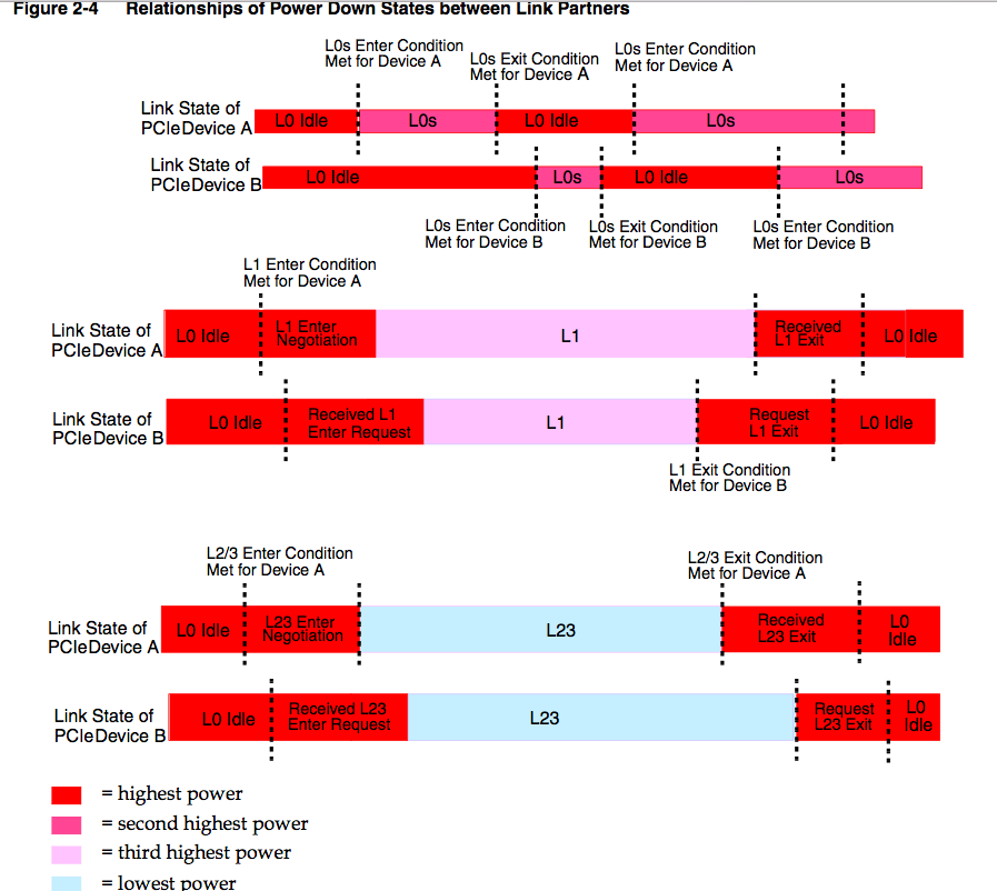
3.9 Power Management
3.10 Single Root I/O Virtualization(SR-IOV)
支持多个系统镜像共享PCIe硬件资源,通过CX_SRIOV_ENABLE开启。包括Function Level Reset(FLR)和Alternate Routing ID Interpretation(ARI)
四、时钟和复位信号
4.1 core_clk
62.5MHz/125MHz/250MHz/500MHz,所有core的输入信号(除了reset信号)和这个clock同步。
4.2 pipe_clk
pipe上的信号由这个时钟同步,为125MHz或者250MHz,影响freq_step module
4.3 core_rst_n
复位core,除了PMC模块
4.4 aux_clk
用于PMC域
4.5 pwr_rst_n
复位PMC模块,用于上电时的冷复位,会复位aux_clk域的所有寄存器。
4.6 sticky_rst_n
复位所有configuration register space中的sticky bit registers。
4.7 non_sticky_rst_n
复位configuration register space中所有non-sticky bit registers。
4.8 app_init_rst
给下游设备发送一个Hot Reset。
4.9 app_req_retry_en
延迟配置请求直到初始化完成,EP有效。
4.10 training_rst_n
Hot Reset from upstream component
五、PCIe寄存器
5.1 EP模式
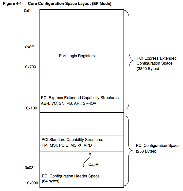
每个function有4096 bytes配置空间,分为:
- 256字节PCI配置空间
64字节的PCI 3.0兼容配置空间header,PCI标准功能结构链表(在偏移0x40之后任意位置开始)。 - 3840字节的PCIe扩展配置空间(0x100开始)
包括PCIe扩展功能结构链表(0x100开始),端口逻辑寄存器(0x700开始)
包括PF(Physical Function) register map和VF(Virtual Function) register map。
应用通过DBI访问配置寄存器,Bits[11:0]选择target function,Bits[18:16]选择target physical function(在没有使能SR-IOV的情况下)。否则通过dbi_func_num和dbi_vfunc_num表征是哪一个PF或者VF。
配置空间映射:分为PF和VF
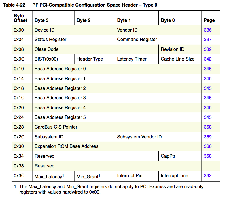
- PF PCI-Compatible Configuration Header Register
PF PCI Standard Capability Structures Register
PF PCI Express Extended Capability Register
VF PCI-Compatible Configuration Header Register
VF PCI Standard Capability Structures Register
5.2 RC模式
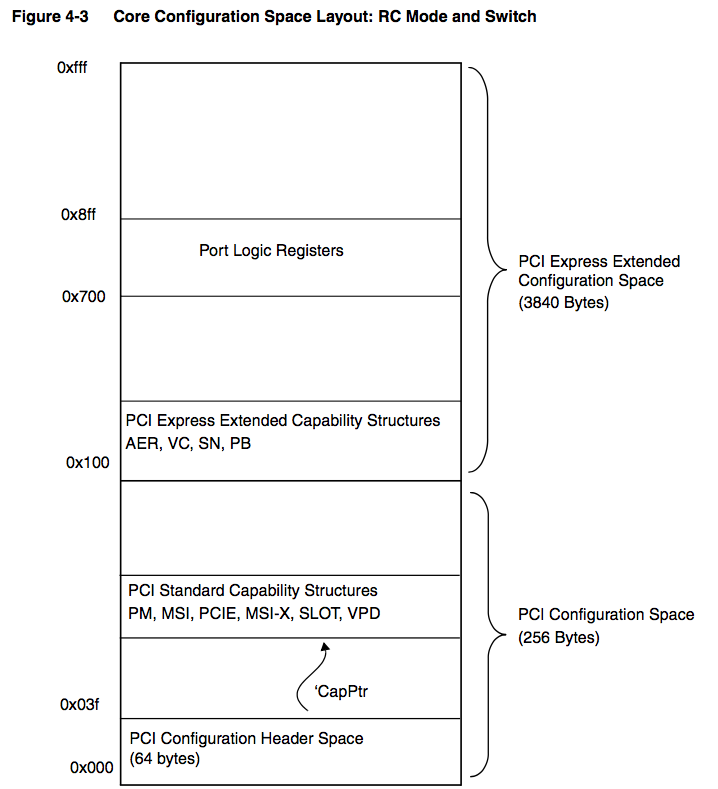
每个function有4K Bytes配置空间,分为:
- 256字节的PCI 3.0 兼容Configuration Space Header
- PCI 功能结构体,从偏移0x40开始
- PCIe扩展配置空间,从偏移0x100开始
- 端口逻辑寄存器(vendor-specific registers),从0x700开始
六、软件工作(与usb3.0比较)
PCIe有三个独立的地址空间:mem空间、I/O空间和配置空间,对每个设备都有其配置空间,通过ID寻址(USB通过协议通信,实际上在文件系统中,都统一为ID寻址,通过总线/设备/接口进行标识,PCIe的function对应usb的interface)。
designware的PCIe driver在内核中位于drivers/pci/host/pcie-designware.c,像samsung exynos的PCIe host驱动为同目录下pci-exynos.c。
这里的pcie-designware.c只是作为一个接口库供驱动调用,并不向kernel注册设备(usb dwc3自己是一个platform device,然后再去probe厂商定义的usb device)。
6.1 准备工作
时钟和mem地址映射
| clk name | description |
|---|---|
| pcie clk | |
| pcie bus clk | |
| elbi base | Customer defined mem region |
| phy base | phy寄存器基址 |
| block base | ?? |
| irq | 中断号 |
| msi irq | 如果支持msi的话,配置对应的中断号 |
| 配置空间地址 | 内核中通过pcie_port管理 |
| dbi base | 配置空间基址 |
| mem base | mem空间基址 |
| num of lanes | 几条lane |
6.2 PCIe操作流程
| procedure | description |
|---|---|
| host init | 初始化RC,根据驱动参数进行配置,建立链路 |
| scan | 扫描设备 |
6.2.1 Establish Link流程
参考自drivers/host/pci-exynos.c
| procedure | description |
|---|---|
| assert core reset and phy reset | |
| de-assert phy reset | |
| power on phy | |
| initialize phy | |
| pulse for common reset | |
| de-assert core reset | |
| setup root complex | 设置configuration space header |
| enable ltssm | 开始链路训练 |
6.2.2 PCIe设备枚举
在pcie-designware.c中通过调用pci_scan_root_bus_msi(使能了MSI)或者pci_scan_root_bus,然后进到pci/probe.c。
附录: Acknowledge
DLLP是由Data Link Layer管理的数据包,包括NAK,High Priority ACK, Flow Control, Vendor Control, Power Management。
| abbreviation | description |
|---|---|
| DLLP | Data Link Layer Packets |
| DBI | Data Bus Interface |
| CDM | Configuration-Dependent Module |
| LBC | Local Bus Controller |
| ELBI | External Local Bus Interface |
| iATU | Internal Address Translation Unit |


 1935
1935

 被折叠的 条评论
为什么被折叠?
被折叠的 条评论
为什么被折叠?
 到【灌水乐园】发言


