


All information in this blog Refer to The Definitive Guide to ARM Cortex-M3 and Cortex-M4 Processors, 3rd Edition
This is series blogs about RTOS, which is based on Cortex-M3 and Cortex-M4. All the code you will see is based on MDK-ARM. I will split it to three parts. And I found that, for everything, the difficult part is at the beginning, so I will spend lots of my effort on the first part, it is boring, but I hope I can help all reader.
Let’s started with a little about OS. The Cortex-M3 and Cortex-M4 processors have a built-in system tick timer, which is called Systick, and we can use Systick to generate regular timer interrupts for OS timekeeping, so that they can support embedded OSs efficiently. Actually, if they don’t support Systick, we can use common timer to generate regular timer interrupts for OS timekeeping. But Using Systick is a common way. For OS, only if the programme can get regular timer interrupts and use the interrupt to switch context, it can achieve OS.
The vital section of OS is context switch, and the Cortex-M3 and Cortex-M4 processors also have banked stacked pointers which do a important job for context switch: for OS kernel and interrupts, the Main Stack Pointer (MSP) is used; for application tasks, the Process Stack Pointer (PSP) is used. In this way, the stack used by the OS kernel can be separated from that use by application tasks. For simple applications without an
OS, the MSP can be used all the time.
Part 1 Necessary knowledge about Cortex-M3 and Cortex-M4
During this section, I will discuss Cortex-M3 and Cortex-M4, so that you can know how the program run, all the information in this section will help you understand the third section quickly and smoothly.
Chapter 1 Architecture
Registers
The following registers follow “load-store architecture.”

R0 e R12:Registers R0 to R12 are general purpose registers.
R13 is the Stack Pointer. When we use PUSH and POP operations, this register point which memory we wanna access. Physically there are two different Stack Pointers: the Main Stack Pointer (MSP, or SP_main in some ARM documentation) and Process Stack Pointer (PSP, or SP_process in some ARM documentation).
MSP is the default Stack Pointer. it means that MSP is selected after reset, there is another situation we will use MSP, it’s when the processor is in Handler Mode. The PSP can only be used in Thread Mode.
The selection of StackPointer is determined by a special register called CONTROL. The PSP is normally used when an embedded OS is involved, where the stack for the OS kernel and application tasks are separated. The initial value of PSP is undefined, and the initial value of MSP is taken from the first word of the memory during the reset sequence.
On the third section, I’ll intruduce this register again and illustrate how to use this register.
R14 is called the Link Register (LR). This is used for holding the return address
when calling a function or subroutine. When a function or subroutine call is made, the
value of LR is updated automatically. If a function needs to call another function or
subroutine, it needs to save the value of LR in the stack first. Otherwise, the current
value in LR will be lost when the function call is made.
R15 is the Program Counter (PC). It is readable and writeable: a read returns the
current instruction address plus 4. Writing to PC causes a branch operation.
Special registers
Special registers are not memory mapped, and can be accessed using special register
access instructions such as MSR and MRS.
Program Status Register: Application PSR (APSR)
Execution PSR (EPSR)
Interrupt PSR (IPSR)
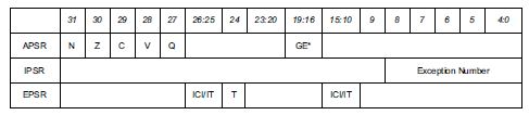
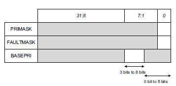
PRIMASK, FAULTMASK, and BASEPRI registers
The CONTROL register defines:
• The selection of stack pointer (Main Stack Point/Process Stack Pointer)
• Access level in Thread mode (Privileged/Unprivileged)


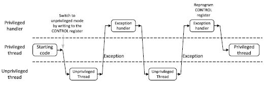
When an embedded OS is used, the CONTROL register could be reprogrammed
at each context switch to allow some application tasks to run with privileged access
level and the others to run with unprivileged access level.
If you wanna get more details about all the sepcial registers and Floating point registers, please search on the internet.
Memory map


Stack memory
This is the extraordinarily important section. I hope all the reader can understand this section.
When the processor is started, the SP is set to the end of the memory space
reserved for stack memory. For each PUSH operation, the processor first decrements
the SP, then stores the value in the memory location pointed by SP. During operations,
the SP points to the memory location where the last data was pushed to the
stack. In a POP operation, the value of the memory location pointed by SP is read, and
then the value of SP is incremented automatically.
The most common uses for PUSH and POP instructions are to save contents
of register banks when a function/subroutine call is made. At the beginning of
the function call, the contents of some of the registers can be saved to the stack
using the PUSH instruction, and then restored to their original values at the end
of the function using the POP instruction. Since the registers in the register bank are
32 bits, each memory transfer generated by stack PUSH and stack POP transfers
at least 1 word (4 bytes) of data, and the addresses are always aligned to 4-byte
boundaries. The lowest two bits of the SP are always zero.
As mentioned previously, the selection between MSP and PSP can be controlled by the value of SPSEL in bit 1 of the CONTROL register. If this bit is 0, Thread mode uses MSP for the stack operation. Otherwise, Thread mode uses the PSP. In addition, during exception return from Handler mode toThread mode, the selection can be controlled by the value of EXC_RETURN (exception return) value. In that case the value of SPSEL will be updated by the processor hardware accordingly.
When embedded systems use an embedded OS, they often use separate memory
areas for application stack and the kernel stack. As a result, the PSP is used and
switching of SP selection takes place in exception entry and exception exit. Note that the automatic “Stacking” and “Unstacking” stagesuse PSP. The separating stack arrangement can prevent a stack corruption or error in an application task from damaging the stack use by the OS. It also simplifies the OS design and hence allows faster context switching.

Exceptions and interrupts
Exceptions and interrupts is vital for Cortex, but here, I don’t introduce it. All reader can get something you need online.
Other characters about architecture whitout strong relationship with OS have not mentioned. If you are intereted in it, please check it online.


 153
153


 被折叠的 条评论
为什么被折叠?
被折叠的 条评论
为什么被折叠?
 到【灌水乐园】发言


