


目录
简介
Power Management Subsystem(电源管理子系统)在Zephyr下是负责管理电源模式的系统,它制定了一套规范与模型由SOC开发者实现在这个系统上属于自己的电源模式,并且还提供了几种电源管理策略,开发者基于这些策略为SOC开发出对应的电源模式
电源的管理统一由Power Management Subsystem控制,在Power Management Subsystem里定义了部分Weak函数,当发生电源操作时电源管理子系统会去调用这些函数,如果开发者没有实现那么什么都不会做,如果实现了则调用开发者的实现,这样针对每个不同的SOC体系都不需要修改内核代码可以轻松完成对不同SOC的适配
前景补充
Power Management Subsystem对一些电源管理的方法起了一些术语名称,下面是对这些术语名称的解释
SOC Interface
SOC Interface(SOC接口)这是对具备SOC知识并为硬件功能提供接口的组件的通用术语,它将特定于SOC的实现抽象为应用程序和操作系统,简单一点说就是将SOC接口抽象为HAL层(驱动层)
IDLE Thread
IDLE Thread(空闲线程)是Zephyr下空闲线程,它是Zephyr RTOS里优先级最低的线程,当没有线程工作时会进入到这个线程,并将这个线程的CPU工作时间设置为最近一次要被唤醒线程的Ticks步数,倘若Ticks步数是指定电源模式则进入指定电源模式
* Tickless Idle
Tickless Idle(无刻点闲置)可以理解为基于Idle线程的低功耗实现,它的主要作用就是当当前系统不在工作时(没有线程工作或所有线程都进行了Sleep)会被切换到Idle线程,并根据当前的电源策略来进行对应的低功耗处理
Power Gating
Power Gating(功率选通)是实现低功耗的一种方法,比如部分集成电路里集成了开关电路,通过将一些能够被自由切断与连接的电路进行切断,屏蔽电流流通节省功耗,当唤醒时在将电路接通
Power State
Power State(电源状态)是在SOC处理电源时的状态变化描述,在SOC级别实现的处理器和设备电源时的一个状态,通过Power State可以得知当前处于怎样的一个电源状态
Device Runtime Power Management
Device Runtime Power Management(设备运行时电源管理),它的作用是在运行时去将一些未使用或空闲的设备进行关闭,同时它会自动根据使用情况开启与关闭,达到运行时系统节能的状态
系统的组成
Power Management Subsystem将电源管理分成三个部分:System Power Management、Device Power Management Infrastructure、Device Runtime Power Management
System Power Management
System Power Management(系统电源管理)体现Idle线程进行调度上面,当开启CONFIG_PM时,如果内核此时没有调度的话,电源管理系统可以根据选定的电源管理策略和内核分配的空闲时间,将空闲系统置于支持的电源状态之一,它主要体现在系统层面。
应用程序负责设置唤醒事件,唤醒事件通常是由一个SoC外围模块(如SysTick、RTC、Timer或GPIO)触发的中断。根据输入的电源模式,只有一些SoC外围模块可能处于激活状态,并可用作唤醒源
同时当要切换到IDLE线程时会调用钩子函数:suspend(暂停)/resume(恢复),即当进入电源模式之前调用一次suspend函数,出来之后调用resume函数
下图是System Power Management调用过程:

同时System Power Management提供两个子模块:
* Power State
Power State(电源状态)当SOC电源模式进行切换时Zephyr内部会用pm_state来标识当前SOC电源模式(由SOC开发者实现),表明当前系统在进行怎样的电源变化,同时开发者也要实现这些操作,pm_state可以取如下值:
| 枚举 | 意义 |
|---|---|
| PM_STATE_ACTIVE | 运行时活动状态 系统已完全通电并处于活动状态 |
| PM_STATE_RUNTIME_IDLE | 运行时空闲状态 运行时空闲是一种系统睡眠状态,在这种状态下,所有内核都会进入可能最深的空闲状态,并等待中断,对设备没有任何要求,使其处于当前状态 |
| PM_STATE_SUSPEND_TO_IDLE | 挂起到空闲状态 系统会经历一个正常的平台挂起,将所有内核置于尽可能深的空闲状态,并可能将外围设备置于低功耗状态。不会丢失任何操作状态(即cpu核心不会丢失执行上下文),因此系统可以很容易地返回到中断的位置 |
| PM_STATE_STANDBY | 待机状态 除了将外围设备置于低功耗状态之外,所有非引导CPU都将关闭电源。相对于挂起到空闲,它应该可以节省更多的能量,但恢复延迟通常会大于该状态。但在uniprocesser系统上,它应该是与挂起到空闲状态相同的状态 |
| PM_STATE_SUSPEND_TO_RAM | 挂起到ram状态 此状态通过尽可能多地关闭系统电源提供了显著的节能,此时内存应置于自刷新模式以保留其内容。设备和CPU的状态保存在内存中,可能需要ROM中的一些引导代码才能从中恢复系统 |
| PM_STATE_SUSPEND_TO_DISK | 挂起到磁盘状态 此状态通过关闭尽可能多的系统(包括内存)来显著节约能源。内存的内容被写入磁盘或其他非易失性存储器,恢复时,借助引导代码将其读回内存,将系统恢复到挂起到磁盘的同一执行点 |
| PM_STATE_SOFT_OFF | 软关闭状态 此状态消耗的电量最小,并且需要较大的延迟才能返回到运行时活动状态。系统的内容(CPU和内存)将不会被保留,因此系统将重新启动,就像从初始通电和内核引导开始一样 |
* Power Management Policies
Power Management Policies(电源管理策略)是处理电源状态的几种策略方针,它支持如下几个策略:
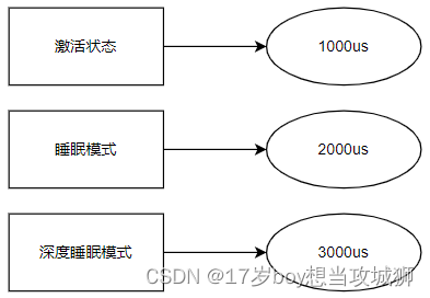
1. Residency
Residency(派驻策略)策略实现方式是为每个电源状态设置一个休眠时间,发生Sleep、Deep Sleep或其它引起休眠的操作时,System Power Management会调用Residency的休眠策略,Tickless Idle会取出最近一次要被唤醒线程的剩余Timeout,然后把这个Timeout与电源状态的休眠时间做一个比较,如果大于等于这个休眠时间则调用Weak协议函数然后进入指定休眠状态
2. Application
Application(应用策略)策略实现方式是由应用程序来实现如何完成休眠工作
3. Dummy
Dummy(假设策略)策略一般用于测试,它会轮流切换不同的电源状态,如有四种电源状态,如果使用Dummy策略会在这四种电源里轮流切换,确保每一种电源状态能够被切换到
Device Power Management Infrastructure
Device Power Management Infrastructure(设备电源管理基础架构)是基础设备模型实现框架,SOC开发者需要根据这个规范实现对应的PM设备模型,它主要体现在控制设备层面上,同时它支持支持两种设备电源管理方法:
Distributed method
Distributed method(分布式)是由应用层直接与PM设备进行交互,根据当前应用程序的工作状态来修改当前SOC的状态,即便当前有线程正在工作也可以让SOC进入指定的低功耗状态,通俗易懂的说就是应用层可以直接访问PM Driver的API接口,直接主动进入指定低功耗状态,但是需要开发者自己去设置当前SOC电源,并且开发者需要根据不同的管理策略做对应的电源处理
Central method
Central method(中心式)这种方式由System Power Management统一处理,它处理的方式就是只有在当前没有任何线程处于工作状态,从沉睡队列里取出一个即将要Timeout的线程(即将要唤醒的线程),如果这个线程沉睡的Ticks步数大于等于指定沉睡模式时会去自己设置SOC电源状态然后进入指定电源模式,并且在进入深度模式时会自动去检查是否满足进入条件,如进入之前需要确保没有一个工作线程,同时最近一次唤醒的线程需大于等于指定沉睡模式的Ticks步数,当然要决定进入深度睡眠的话还需要保证当前设备不能被应用层的一些硬件中断事务打断,如应用层设置了i2c中断或usart中断,如果产生中断这个线程会被唤醒,所以System Power Management需要将这部分中断进行屏蔽,同时System Power Management也会自动设置电源状态

下面是它的设备模型规范介绍,开发者需要实现的几种状态与操作:
Device Power Management States
Device Power Management States(设备电源管理状态)在电源管理子系统里负责标识当前SOC设备的状态,在Device Power Management States里定义了四种设备状态。这些状态是根据在这些状态中丢失的设备上下文的程度、为省电而执行的操作类型以及状态转换对设备行为的影响来分类的,设备上下文包括设备寄存器、时钟、内存等这些相关联的东西
Device Power Management States将电源定义为如下几种状态(模式),这些状态变化时与系统层的System Power Management Power State状态是挂钩的:
| 状态值 | 状态 |
|---|---|
| PM_DEVICE_STATE_ACTIVE | 激活状态 设备正常运行,保留所有设备上下文 |
| PM_DEVICE_STATE_LOW_POWER | 低功率状态(睡眠状态 硬件保留设备上下文,驱动程序无需还原设备上下文 |
| PM_DEVICE_STATE_SUSPEND | 挂起状态(深度睡眠状态) 硬件会丢失大多数设备上下文,设备驱动程序必须保存、还原或重新初始化硬件丢失的任何上下文 |
| PM_DEVICE_STATE_SUSPENDING | 转换状态(不属于电源模式) 设备正在从PM_DEVICE_STATE_ACTIVE状态到PM_DEVICE_STATE_SUSPEND状态转换 |
| PM_DEVICE_STATE_RESUMING | 转换状态(不属于电源模式) 设备正在从PM_DEVICE_STATE_SUSPEND状态到PM_DEVICE_STATE_ACTIVE状态转换 |
| PM_DEVICE_STATE_OFF | 关闭状态 设备电源已完全断开,进入此状态时,设备上下文将丢失,重新开机时需要重新初始化设备 |
Device Power Management Operations
Device Power Management Operations(设备电源管理操作)在电源管理子系统里负责对驱动程序提供功能控制接口,以指示要执行的电源管理操作,同时设置当前电源系统的状态,例如某个外设设备支持电源管理,那么这个外设驱动需要遵循PM设备模型框架,同时定义电源状态与对应的操作,具体状态可以参考System Power Management Power State和Device Power Management States两个条目
Device Power Management Operations提供了两种电源操作命令:
| 命令 | 作用 |
|---|---|
| PM_DEVICE_STATE_SET | 设置要操作的电源状态 |
| PM_DEVICE_STATE_GET | 获取当前电源状态 |
每个PM驱动需要实现如下操作:
- 实现SOC支持的电源模式
- 实现SOC支持的电源模式转换,从一个电源状态到另外一个电源状态的切换
- 处理在进行电源转换时所需要的操作
以下是PM驱动程序在电源状态转换期间可能执行的一些操作示例:
- 保存/还原电源状态
- 开启/关闭时钟
- 开启/关闭电源
- 屏蔽/取消屏蔽中断
除此之外还提供了一种比较特殊的机制:Busy Status Indication,下面是它的介绍:
Busy Status Indication
Busy Status Indication(忙状态指示)提供了一种叫做硬件事务的中间保护的机制,这种机制作用是为了解决在进行低功耗模式时有其它设备正在进行读写导致的数据不一致的情况,如Flash设备正在进行写操作,此时进入了低功耗模式将Flash的时钟关闭后会导致数据并没有写完,导致复位后读取时数据不一致的情况
如果使用这种方案的话可以将指定设备设置为“硬件事务的中间保护”意味着这个设备正在进行工作,那么PM电源管理子系统就会对这个设备进行保护,只有在这个设备完成之后才进入低功耗模式,否则不会进入,这样就保证了数据的正确性
Device Runtime Power Management
Device Runtime Power Management(设备运行时电源管理)是PM电源管理子系统提供的一个用于在系统处于活动时来降低功耗的一个服务,它的原理就是在当系统处于正常工作时去将一些处于空闲状态或者没有使用的设备将它关闭,它主要体现在系统层面与设备层面
在Zephyr的Driver Management里面每一个设备都有一个引用计数器,比如我们为某个设备写了一个Driver同时在Dts里面将它开启出来,这个Driver会添加到全局的设备列表里,同时每个设备对应一个引用计数器,当我们使用device_get_binding或其它获取Driver API时都会使引用计数器加1,并且使用一些工作API函数时都会让设备的状态发生变化,Device Runtime Power Management就是通过来遍历这些引用计数器和设备状态来判断这个设备此时是空闲还是未使用,如果是空闲或未使用的话就关闭这个设备的时钟来降低功耗,需要注意如果开启与关闭的前提是这个外设驱动支持PM电源操作,这样Device Runtime Power Management才能去调用它的PM电源API与关闭时钟或者电源,具体可以参考Device Power Management Operations条目
Tickless Idle分析
前言
每个Soc上的Tickless Idle实现不同但是对于Tickless Idle的实现都大同相近,此段落的内容以STM32 ARM Cortex-M系列为例
概念
几乎每个RTOS系统上都有一个Idle线程,这个线程的优先级为最低,当没有线程在工作时或当所有线程进入Sleep时Sched(调度器)会切换到Idle线程,同时会设置一个Timer定时器,这个定时器的Ticks步数就是最近一次要被唤醒线程的Timeout,如果没有线程则是K_TICKS_FOREVER,然后将线程切换到Idle线程里,然后根据Ticks步数进入指定电源模式,若不属于任何电源模式则进入一个暂停模式(需要SOC开发者实现),一般很多处理器都有自己的暂停指令,如Intel处理器中的是hlt指令,它可以让CPU进入暂停状态,什么都不做只有被非屏蔽的中断打断时才会继续工作
但是进入空转并不能实现低功耗,因为只是让CPU暂时不进行工作了,许多外设电路都在工作的,为此引入了Tickless Idle,其实就是对Idle线程进行修改,就是在进入Idle线程时去根据最近一次要被唤醒的Ticks步数与电源状态沉睡时间做比较(Residency策略)去进入指定电源状态,不同的电源状态可以关闭不同的外设,不在单纯当CPU不工作,而是让外设也不工作,如在Stm32上的睡眠模式,它会将SOC上1.8v供电的所有电路全部关闭
实现原理
以Residency策略为例
首先定义你的电源状态沉睡时间,假设定义了三种电源状态,每种状态对应不同的沉睡模式
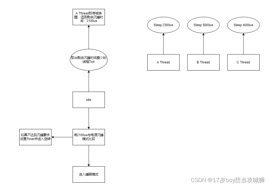
随后在系统开启时会建立四个线程,其中三个为工作线程即用户线程,剩下一个为Idle线程

当A线程调用Sleep时会切换到B,B调用Sleep时会切换到C,当C调用Sleep时会进入到Idle,Idle在取出最近一次要被唤醒的线程Timeout来判定是否要进入电源模式
代码分析
Idle代码存在于:kernel/Idle.c中,将代码展开如下:
/*
 * Copyright (c) 2016 Wind River Systems, Inc.
 *
 * SPDX-License-Identifier: Apache-2.0
 */

#include <kernel.h>
#include <toolchain.h>
#include <linker/sections.h>
#include <drivers/timer/system_timer.h>
#include <wait_q.h>
#include <pm/pm.h>
#include <stdbool.h>
#include <logging/log.h>
#include <ksched.h>
#include <kswap.h>

LOG_MODULE_DECLARE(os, CONFIG_KERNEL_LOG_LEVEL);

/**
 * @brief Indicate that kernel is idling in tickless mode
 *
 * Sets the kernel data structure idle field to either a positive value or
 * K_FOREVER.
 */
static void pm_save_idle(void)
{
#ifdef CONFIG_PM
        int32_t ticks = z_get_next_timeout_expiry();
        _kernel.idle = ticks;

        /*
         * Call the suspend hook function of the soc interface to allow
         * entry into a low power state. The function returns
         * PM_STATE_ACTIVE if low power state was not entered, in which
         * case, kernel does normal idle processing.
         *
         * This function is entered with interrupts disabled. If a low power
         * state was entered, then the hook function should enable inerrupts
         * before exiting. This is because the kernel does not do its own idle
         * processing in those cases i.e. skips k_cpu_idle(). The kernel's
         * idle processing re-enables interrupts which is essential for
         * the kernel's scheduling logic.
         */
        if (pm_system_suspend(ticks) == PM_STATE_ACTIVE) {
                k_cpu_idle();
        }d
#endif
}

void z_pm_save_idle_exit(int32_t ticks)
{
#ifdef CONFIG_PM
        /* Some CPU low power states require notification at the ISR
         * to allow any operations that needs to be done before kernel
         * switches task or processes nested interrupts.
         * This can be simply ignored if not required.
         */
        pm_system_resume();
#endif  /* CONFIG_PM */
        sys_clock_idle_exit();
}

void idle(void *unused1, void *unused2, void *unused3)
{
        ARG_UNUSED(unused1);
        ARG_UNUSED(unused2);
        ARG_UNUSED(unused3);

        __ASSERT_NO_MSG(_current->base.prio >= 0);

        while (true) {
                /* SMP systems without a working IPI can't
                 * actual enter an idle state, because they
                 * can't be notified of scheduler changes
                 * (i.e. threads they should run).  They just
                 * spin in a yield loop.  This is intended as
                 * a fallback configuration for new platform
                 * bringup.
                 */
                if (IS_ENABLED(CONFIG_SMP) &&
                    !IS_ENABLED(CONFIG_SCHED_IPI_SUPPORTED)) {
                        k_busy_wait(100);
                        k_yield();
                        continue;
                }

                /* Note weird API: k_cpu_idle() is called with local
                 * CPU interrupts masked, and returns with them
                 * unmasked.  It does not take a spinlock or other
                 * higher level construct.
                 */
                (void) arch_irq_lock();

                if (IS_ENABLED(CONFIG_PM)) {
                        pm_save_idle();
                } else {
                        k_cpu_idle();
                }
#if !defined(CONFIG_PREEMPT_ENABLED)
# if !defined(CONFIG_USE_SWITCH) || defined(CONFIG_SPARC)
                /* A legacy mess: the idle thread is by definition
                 * preemptible as far as the modern scheduler is
                 * concerned, but older platforms use
                 * CONFIG_PREEMPT_ENABLED=n as an optimization hint
                 * that interrupt exit always returns to the
                 * interrupted context.  So in that setup we need to
                 * explicitly yield in the idle thread otherwise
                 * nothing else will run once it starts.
                 */
                if (_kernel.ready_q.cache != _current) {
                        z_swap_unlocked();
                }
# endif
#endif
        }
}
它的入口函数是idle(void *unused1, void *unused2, void *unused3),这里对它进行一个分析,这里只对重点代码进行分析,首先可以看到第一段while里的代码
首先它会判断当前是否处于SMP模式(多处理器模式),并且如果是SMP的情况下需要保证每个处理器不能处于IPI模式(处理器间中断(即一个CPU向另外一个CPU发起中断请求,多处理器中断),如果处于多处理器模式且处于处理器间中断的情况下则调用k_busy_wait函数进入忙等待状态,这个函数不会让当前线程让出CPU时间,不会出现线程切换,等待其它处理器完成处理,然后调用k_yield函数让出CPU时间,但是有个前提就是当前有线程比当前的线程优先级要高才能让出CPU工作时间
if (IS_ENABLED(CONFIG_SMP) &&
                    !IS_ENABLED(CONFIG_SCHED_IPI_SUPPORTED)) {
                        k_busy_wait(100);
                        k_yield();
                        continue;
}
这段代码是先屏蔽CPU的中断,然后检查有没有CONFIG_PM宏,也就意味着我们需要在Kconfig里将CONFIG_PM开启才能使用PM功能,如果有则调用pm_save_idle,注意这个函数可以理解为Tickless Idle的实现,如果没有则调用k_cpu_idle,也就是最原始的空闲代码,让CPU进入暂停,同时中断解除也是在k_cpu_idle里实现的
(void) arch_irq_lock();

if (IS_ENABLED(CONFIG_PM)) {
	pm_save_idle();
} else {
	k_cpu_idle();
}
然后我们假设我们已经开启了CONFIG_PM宏开启了System Power Management功能,那么就会进入到pm_save_idle函数中去
可以看到pm_save_idle函数里第一行就是预编译命令,如果没有定义CONFIG_PM则不会生成对应的代码,所以如果想要开启System Power Management功能就必须定义CONFIG_PM
#ifdef CONFIG_PM
然后它调用了z_get_next_timeout_expiry函数,这个函数就是取出最近一次要被唤醒线程的Ticks剩余步数,注意从这里其实可以看到它是一个int32_t类型的,所以最大值不会超过int32 MAX
int32_t ticks = z_get_next_timeout_expiry();
_kernel.idle = ticks;
然后它会去调用pm_system_suspend函数去判断ticks是否处于电源状态沉睡时间,如果处于则进入电源状态,如果不处于则返回PM_STATE_ACTIVE,然后调用k_cpu_idle进入暂停
if (pm_system_suspend(ticks) == PM_STATE_ACTIVE) {

	k_cpu_idle();

}
我们可以拆开pm_system_suspend函数看一下:
enum pm_state pm_system_suspend(int32_t ticks)
{
	SYS_PORT_TRACING_FUNC_ENTER(pm, system_suspend, ticks);
	z_power_state = pm_policy_next_state(ticks);
	if (z_power_state.state == PM_STATE_ACTIVE) {
		LOG_DBG("No PM operations done.");
		SYS_PORT_TRACING_FUNC_EXIT(pm, system_suspend, ticks, z_power_state.state);
		return z_power_state.state;
	}
	post_ops_done = 0;

	if (ticks != K_TICKS_FOREVER) {
		/*
		 * Just a sanity check in case the policy manager does not
		 * handle this error condition properly.
		 */
		__ASSERT(z_power_state.min_residency_us >=
			z_power_state.exit_latency_us,
			"min_residency_us < exit_latency_us");

		/*
		 * We need to set the timer to interrupt a little bit early to
		 * accommodate the time required by the CPU to fully wake up.
		 */
		z_set_timeout_expiry(ticks -
		     k_us_to_ticks_ceil32(z_power_state.exit_latency_us), true);
	}

#if CONFIG_PM_DEVICE

	bool should_resume_devices = true;

	switch (z_power_state.state) {
	case PM_STATE_RUNTIME_IDLE:
		__fallthrough;
	case PM_STATE_SUSPEND_TO_IDLE:
		__fallthrough;
	case PM_STATE_STANDBY:
		/* low power peripherals. */
		if (pm_low_power_devices()) {
			SYS_PORT_TRACING_FUNC_EXIT(pm, system_suspend,
					ticks, _handle_device_abort(z_power_state));
			return _handle_device_abort(z_power_state);
		}
		break;
	case PM_STATE_SUSPEND_TO_RAM:
		__fallthrough;
	case PM_STATE_SUSPEND_TO_DISK:
		if (pm_suspend_devices()) {
			SYS_PORT_TRACING_FUNC_EXIT(pm, system_suspend,
					ticks, _handle_device_abort(z_power_state));
			return _handle_device_abort(z_power_state);
		}
		break;
	default:
		should_resume_devices = false;
		break;
	}
#endif
	/*
	 * This function runs with interruptions locked but it is
	 * expected the SoC to unlock them in
	 * pm_power_state_exit_post_ops() when returning to active
	 * state. We don't want to be scheduled out yet, first we need
	 * to send a notification about leaving the idle state. So,
	 * we lock the scheduler here and unlock just after we have
	 * sent the notification in pm_system_resume().
	 */
	k_sched_lock();
	pm_debug_start_timer();
	/* Enter power state */
	pm_state_notify(true);
	pm_power_state_set(z_power_state);
	pm_debug_stop_timer();

	/* Wake up sequence starts here */
#if CONFIG_PM_DEVICE
	if (should_resume_devices) {
		/* Turn on peripherals and restore device states as necessary */
		pm_resume_devices();
	}
#endif
	pm_log_debug_info(z_power_state.state);
	pm_system_resume();
	k_sched_unlock();
	SYS_PORT_TRACING_FUNC_EXIT(pm, system_suspend, ticks, z_power_state.state);
	return z_power_state.state;
}
可以看到第一行调用了pm_policy_next_state函数,注意这个函数会根据你使用的策略而编译对应不同的文件,如使用的是Residency策略,它对应的是pm_residency.c里的实现,所以在这里就体现到Power Management Policies
z_power_state = pm_policy_next_state(ticks);
这里我将pm_residency.c里的代码拿出来看下它的具体实现:
static const struct pm_state_info pm_min_residency[] =
	PM_STATE_INFO_DT_ITEMS_LIST(DT_NODELABEL(cpu0));

struct pm_state_info pm_policy_next_state(int32_t ticks)
{
	int i;

	for (i = ARRAY_SIZE(pm_min_residency) - 1; i >= 0; i--) {
		uint32_t min_residency, exit_latency;

		if (!pm_constraint_get(pm_min_residency[i].state)) {
			continue;
		}

		min_residency = k_us_to_ticks_ceil32(
			    pm_min_residency[i].min_residency_us);
		exit_latency = k_us_to_ticks_ceil32(
			    pm_min_residency[i].exit_latency_us);
		__ASSERT(min_residency > exit_latency,
				"min_residency_us < exit_latency_us");

		if ((ticks == K_TICKS_FOREVER) ||
		    (ticks >= (min_residency + exit_latency))) {
			LOG_DBG("Selected power state %d "
				"(ticks: %d, min_residency: %u)",
				pm_min_residency[i].state, ticks,
				pm_min_residency[i].min_residency_us);
			return pm_min_residency[i];
		}
	}

	LOG_DBG("No suitable power state found!");
	return (struct pm_state_info){PM_STATE_ACTIVE, 0, 0};
}
首先可以看到这么一行结构体定义,这里是定义你电源模式的沉睡时间,注意在2.0以前使用的是CONFIG配置,需要主动修改这里的代码,但是到了2.0以后修改为了DTS方式来修改,这里它使用PM_STATE_INFO_DT_ITEMS_LIST、DT_NODELABEL来获取DTS里的定义并按照成GCC结构体初始化的方式进行初始化
static const struct pm_state_info pm_min_residency[] =
	PM_STATE_INFO_DT_ITEMS_LIST(DT_NODELABEL(cpu0));
这里把这个结构体拆开看一下:
struct pm_state_info {
	enum pm_state state;

	/**
	 * Some platforms have multiple states that map to
	 * one Zephyr power state. This property allows the platform
	 * distinguish them. e.g:
	 *
	 *	power-states {
	 *		state0: state0 {
	 *			compatible = "zephyr,power-state";
	 *			power-state-name = "suspend-to-idle";
	 *			substate-id = <1>;
	 *			min-residency-us = <10000>;
	 *			exit-latency-us = <100>;
	 *		};
	 *		state1: state1 {
	 *			compatible = "zephyr,power-state";
	 *			power-state-name = "suspend-to-idle";
	 *			substate-id = <2>;
	 *			min-residency-us = <20000>;
	 *			exit-latency-us = <200>;
	 *		};
	 *	}
	 */
	uint8_t substate_id;

	/**
	 * Minimum residency duration in microseconds. It is the minimum
	 * time for a given idle state to be worthwhile energywise.
	 *
	 * @note 0 means that this property is not available for this state.
	 */
	uint32_t min_residency_us;

	/**
	 * Worst case latency in microseconds required to exit the idle state.
	 *
	 * @note 0 means that this property is not available for this state.
	 */
	uint32_t exit_latency_us;
};
以下是每个成员的作用:
| 成员名 | 作用 |
|---|---|
| state | 电源状态,具体可以参考Power State |
| substate_id | 电源模式id |
| min_residency_us | 最小沉睡时间 |
| exit_latency_us | 唤醒时间 |
这里说一下min_residency_us和exit_latency_us的作用
min_residency_us是指电源模式最小沉睡时间,如果大于等于这个值就会进入到对应的电源模式
exit_latency_us是指唤醒时间,也就是当你CPU被唤醒的时候,你开启外设或恢复现场大概需要多久
然后我们在看下DTS里的定义:
cpus {
 		cpu0: cpu@0 {
 			device_type = "cpu";
 			cpu-power-states = <&state0 &state1>;
 		};
 	};

power-states {
	 		state0: state0 {
	 			compatible = "zephyr,power-state";
	 			power-state-name = "suspend-to-idle";
	 			substate-id = <1>;
	 			min-residency-us = <10000>;
	 			exit-latency-us = <100>;
	 		};
	 		state1: state1 {
	 			compatible = "zephyr,power-state";
	 			power-state-name = "suspend-to-idle";
	 			substate-id = <2>;
	 			min-residency-us = <20000>;
	 			exit-latency-us = <200>;
	 		};
	 	}
- power-state-name
对应Power State,比如想要将state设置为PM_STATE_SUSPEND_TO_IDLE,那么就需要写成小写字符串为:“suspend-to-idle”,就会自动转化为PM_STATE_SUSPEND_TO_IDLE,west会自动转换与生成 - substate-id
状态id,按顺序编写,用于表明这是第几个电源状态,下标从1开始 - min-residency-us
电源模式最小沉睡时间 - exit-latency-us
恢复线程需要时间
接下来就是分析电源调度策略的函数:pm_policy_next_state
首先它会调用pm_constraint_get函数去判断当前状态是否为有效状态即System Power Management Power State里定义的状态,如果想要增加你的状态需要到enum pm_state里去增加
if (!pm_constraint_get(pm_min_residency[i].state)) {
			continue;
}
然后紧接着就会将定义的us转化为ticks步数,这里提以下ticks步数与us的对应关系,Timer每频率跳动一次会使计数器减一或递增一,这个跳动次数就是ticks步数,而跳到到指定数所耗费的时间就是us
min_residency = k_us_to_ticks_ceil32(
			    pm_min_residency[i].min_residency_us);
exit_latency = k_us_to_ticks_ceil32(
			    pm_min_residency[i].exit_latency_us);
然后就是判断ticks是否为K_TICKS_FOREVER或者处于某个电源模式的沉睡时间,如果是就返回数组里对应的电源结构体
if ((ticks == K_TICKS_FOREVER) ||
		    (ticks >= (min_residency + exit_latency))) {
			LOG_DBG("Selected power state %d "
				"(ticks: %d, min_residency: %u)",
				pm_min_residency[i].state, ticks,
				pm_min_residency[i].min_residency_us);
			return pm_min_residency[i];
		}
如果没有则定义一个临时结构体并将state初始化为PM_STATE_ACTIVE,这里就与pm_save_idle函数里的判断语句对应起来了,如果是PM_STATE_ACTIVE则调用k_cpu_idle进入暂停
LOG_DBG("No suitable power state found!");
return (struct pm_state_info){PM_STATE_ACTIVE, 0, 0};
然后判断ticks是否不是K_TICKS_FOREVER,只有在不是K_TICKS_FOREVER才会去设置定时器,因为如果是K_TICKS_FOREVER就不需要设置定时器了,直接进入睡眠模式以后就不需要唤醒了,如果不是是则设置调用z_set_timeout_expiry设置定时器,注意看在设置定时器的时候定时的ticks步数是ticks - k_us_to_ticks_ceil32(z_power_state.exit_latency_us),因为唤醒是需要时间的,所以将定时器设置了提前个exit_latency_us
if (ticks != K_TICKS_FOREVER) {
        /*
         * Just a sanity check in case the policy manager does not
         * handle this error condition properly.
         */
        __ASSERT(z_power_state.min_residency_us >=
            z_power_state.exit_latency_us,
            "min_residency_us < exit_latency_us");

        /*
         * We need to set the timer to interrupt a little bit early to
         * accommodate the time required by the CPU to fully wake up.
         */
        z_set_timeout_expiry(ticks -
             k_us_to_ticks_ceil32(z_power_state.exit_latency_us), true);
    }
这里就是判断是否开启CONFIG_PM_DEVICE,如果开启了则根据当前判断是否要设置设备模式,如果是则会去调用对应的函数(如pm_low_power_devices)去设置支持PM的设备为指定模式(注意这里是所有的设备,不是某一个指定的设备),注意需要这些设备的Driver支持PM操作
#if CONFIG_PM_DEVICE

	bool should_resume_devices = true;

	switch (z_power_state.state) {
	case PM_STATE_RUNTIME_IDLE:
		__fallthrough;
	case PM_STATE_SUSPEND_TO_IDLE:
		__fallthrough;
	case PM_STATE_STANDBY:
		/* low power peripherals. */
		if (pm_low_power_devices()) {
			SYS_PORT_TRACING_FUNC_EXIT(pm, system_suspend,
					ticks, _handle_device_abort(z_power_state));
			return _handle_device_abort(z_power_state);
		}
		break;
	case PM_STATE_SUSPEND_TO_RAM:
		__fallthrough;
	case PM_STATE_SUSPEND_TO_DISK:
		if (pm_suspend_devices()) {
			SYS_PORT_TRACING_FUNC_EXIT(pm, system_suspend,
					ticks, _handle_device_abort(z_power_state));
			return _handle_device_abort(z_power_state);
		}
		break;
	default:
		should_resume_devices = false;
		break;
	}
#endif
最后这一部分就是进入电源模式了,因为到了这一步就说明已经确定电源模式了,所以首先调用了k_sched_lock函数来锁定调度,其次调用了pm_state_notify函数调用HOOK事件,这个函数后面会仔细说一下,最终核心在于pm_power_state_set这个函数,这个函数是一个weak函数,它只有定义没有实现,这一步是需要SOC开发者实现的,这个函数就是进入电源模式的函数
/*
	 * This function runs with interruptions locked but it is
	 * expected the SoC to unlock them in
	 * pm_power_state_exit_post_ops() when returning to active
	 * state. We don't want to be scheduled out yet, first we need
	 * to send a notification about leaving the idle state. So,
	 * we lock the scheduler here and unlock just after we have
	 * sent the notification in pm_system_resume().
	 */
	k_sched_lock();
	pm_debug_start_timer();
	/* Enter power state */
	pm_state_notify(true);
	pm_power_state_set(z_power_state);
	pm_debug_stop_timer();
这里我将stm32l5的实现code拿出来,它是根据substate_id来设置的,不过它的关系与state是对应的,可以看到它调用了STM32的LL库来完成这些低功耗
/* Invoke Low Power/System Off specific Tasks */
__weak void pm_power_state_set(struct pm_state_info info)
{
	if (info.state != PM_STATE_SUSPEND_TO_IDLE) {
		LOG_DBG("Unsupported power state %u", info.state);
		return;
	}

	switch (info.substate_id) {
	case 1: /* this corresponds to the STOP0 mode: */
		/* ensure the proper wake-up system clock */
		LL_RCC_SetClkAfterWakeFromStop(RCC_STOP_WAKEUPCLOCK_SELECTED);
		/* enter STOP0 mode */
		LL_PWR_SetPowerMode(LL_PWR_MODE_STOP0);
		LL_LPM_EnableDeepSleep();
		/* enter SLEEP mode : WFE or WFI */
		k_cpu_idle();
		break;
	case 2: /* this corresponds to the STOP1 mode: */
		/* ensure the proper wake-up system clock */
		LL_RCC_SetClkAfterWakeFromStop(RCC_STOP_WAKEUPCLOCK_SELECTED);
		/* enter STOP1 mode */
		LL_PWR_SetPowerMode(LL_PWR_MODE_STOP1);
		LL_LPM_EnableDeepSleep();
		/* enter SLEEP mode : WFE or WFI */
		k_cpu_idle();
		break;
	case 3: /* this corresponds to the STOP2 mode: */
		/* ensure the proper wake-up system clock */
		LL_RCC_SetClkAfterWakeFromStop(RCC_STOP_WAKEUPCLOCK_SELECTED);
#ifdef PWR_CR1_RRSTP
		LL_PWR_DisableSRAM3Retention();
#endif /* PWR_CR1_RRSTP */
		/* enter STOP2 mode */
		LL_PWR_SetPowerMode(LL_PWR_MODE_STOP2);
		LL_LPM_EnableDeepSleep();
		/* enter SLEEP mode : WFE or WFI */
		k_cpu_idle();
		break;
	default:
		LOG_DBG("Unsupported power state substate-id %u",
			info.substate_id);
		break;
	}
}
这里以substate_1为例,它调用了LL_RCC_SetClkAfterWakeFromStop函数来设置唤醒条件,即通过RCC来唤醒
LL_RCC_SetClkAfterWakeFromStop(RCC_STOP_WAKEUPCLOCK_SELECTED);
然后设置指定电源模式并使能这个模式,注意此时还是未进入对应电源模式的,这里只是设置了PWR功能寄存器
LL_PWR_SetPowerMode(LL_PWR_MODE_STOP1);
LL_LPM_EnableDeepSleep();
最终这里调用了k_cpu_idle函数,这个函数内部调用arch_cpu_idle函数,这个函数内部也是由SOC开发者实现,在stm32l5中k_cpu_idle实现是使用WFE和WFI这两个指令来完成进入沉睡的
在stm32中低功耗寄存器有三种模式,睡眠、停机、待机三种模式:
睡眠状态执行WFE/WFI指令,CPU会关闭自身时钟不会关闭任何设备(如Timer,Uasrt,GPIO),同时内部寄存器保持通电
停机模式则关闭自身时钟和内部设备时钟还有外部时钟,但不会关闭外设,同时FLASH/RAM保持电源,同时内部寄存器保持通电
待机模式下只有WEAK_UP引脚不会被关闭,其余全部会被关闭,重新被唤醒相当于复位,CPU内部寄存器不会保持通电
在STM32中唤醒源也是有规定的,因为不同的模式下所关闭的总线也是不同的,比如我们设置了内部Timer唤醒模式,在待机模式下内部设备总线时钟会被关闭,所以Timer就不起作用了,只能由外部设备中断,当进入待机模式时内部和外部都会被关闭,只有WEAK_UP引脚不会被关闭,所以只能是WEAK_UP引脚才能设置为唤醒源,其余的外设、引脚它们的总线时钟都会被关闭但FLASH和RAM会保持电源
k_cpu_idle()
当产生RTC闹钟中断时PWR会恢复CPU时钟与外设时钟(这需要一点时间,所以就需要exit_latency_us),然后进入中断函数(STM32下根据模式决定是否进入中断函数,在待机模式会复位,只有在停机模式才会进入到中断函数),当进入中断函数时它会将闹钟关闭,也就是将中断标志位清零,如果不这么做过一会RTC过一会会再次进入闹钟中断
void HAL_RTC_AlarmIRQHandler(RTC_HandleTypeDef* hrtc)
{
  /* Get the AlarmA interrupt source enable status */
  if(__HAL_RTC_ALARM_GET_IT_SOURCE(hrtc, RTC_IT_ALRA) != (uint32_t)RESET)
  {
    /* Get the pending status of the AlarmA Interrupt */
    if(__HAL_RTC_ALARM_GET_FLAG(hrtc, RTC_FLAG_ALRAF) != (uint32_t)RESET)
    {
      /* AlarmA callback */
    #if (USE_HAL_RTC_REGISTER_CALLBACKS == 1)
      hrtc->AlarmAEventCallback(hrtc);
    #else
      HAL_RTC_AlarmAEventCallback(hrtc);
    #endif /* USE_HAL_RTC_REGISTER_CALLBACKS */

      /* Clear the AlarmA interrupt pending bit */
      __HAL_RTC_ALARM_CLEAR_FLAG(hrtc,RTC_FLAG_ALRAF);
    }
  }

  /* Get the AlarmB interrupt source enable status */
  if(__HAL_RTC_ALARM_GET_IT_SOURCE(hrtc, RTC_IT_ALRB) != (uint32_t)RESET)
  {
    /* Get the pending status of the AlarmB Interrupt */
    if(__HAL_RTC_ALARM_GET_FLAG(hrtc, RTC_FLAG_ALRBF) != (uint32_t)RESET)
    {
      /* AlarmB callback */
    #if (USE_HAL_RTC_REGISTER_CALLBACKS == 1)
      hrtc->AlarmBEventCallback(hrtc);
    #else
      HAL_RTCEx_AlarmBEventCallback(hrtc);
    #endif /* USE_HAL_RTC_REGISTER_CALLBACKS */

      /* Clear the AlarmB interrupt pending bit */
      __HAL_RTC_ALARM_CLEAR_FLAG(hrtc,RTC_FLAG_ALRBF);
    }
  }
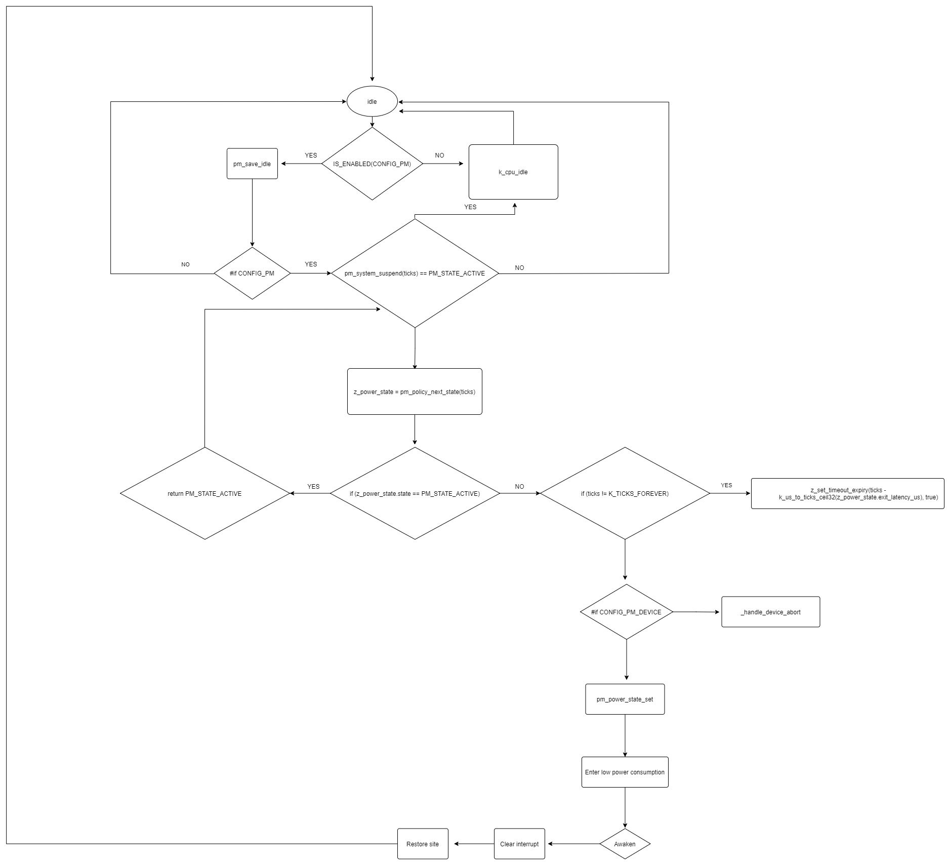
上面说过在停机模式下CPU寄存器是不会停止供电的,同时内部设备寄存器也不会停止供电,但是外设会停止供电,所以如果你想在被唤醒的时候去恢复外设那么需要你在进入沉睡模式前去保存你用到的设备寄存器的值,然后在唤醒后去恢复,在Stm32不会自动保存,所以如果你进入停机模式之前最好保证你的设备或者外设已经完成了工作,在中断结束后会跳回cs指针保存的代码段里继续工作,也就是刚刚的pm_power_state_set函数里执行完k_cpu_idle函数那一段代码,然后继续往下走就会退出pm_power_state_set函数返回到pm_system_suspend函数里,然后在返回到pm_save_idle函数,最后回到idle循环体里这一步耗时都计算在exit_latency_us中,最后重复刚刚的步骤直到Timer被唤醒产生中断进入调度器切换回线程,下图是System Power Management完整工作流程图:
最后回到pm_system_suspend函数时会走到恢复设备的代码,这里会去判断是否开启CONFIG_PM_DEVICE,如果开启则会去调用pm_resume_devices函数,这个函数内部会去调用pm_device_state_set函数将设备设置为激活状态,就是恢复外设,所以当进入低功耗与恢复外设时都需要设备开发者去实现
#if CONFIG_PM_DEVICE
    if (should_resume_devices) {
        /* Turn on peripherals and restore device states as necessary */
        pm_resume_devices();
    }
#endif
z_set_timeout_expiry
这里在说一下z_set_timeout_expiry这个函数,当进入停机模式时内部设备和外设会停止供电,但是有部分外设的时钟电路不会被关闭,其中就有systick,这个系统时钟会一直被供电,待机模式会将它关闭,在STM32里z_set_timeout_expiry函数内部就是使用systick来实现的,它内部调用的是sys_clock_set_timeout函数,它是一个weak函数
void z_set_timeout_expiry(int32_t ticks, bool is_idle)
{
/* Fast CPUs and a 24 bit counter mean that even idle systems
	 * need to wake up multiple times per second.  If the kernel
	 * allows us to miss tick announcements in idle, then shut off
	 * the counter. (Note: we can assume if idle==true that
	 * interrupts are already disabled)
	 */
	if (IS_ENABLED(CONFIG_TICKLESS_KERNEL) && idle && ticks == K_TICKS_FOREVER) {
		SysTick->CTRL &= ~SysTick_CTRL_ENABLE_Msk;
		last_load = TIMER_STOPPED;
		return;
	}

#if defined(CONFIG_TICKLESS_KERNEL)
	uint32_t delay;
	uint32_t val1, val2;
	uint32_t last_load_ = last_load;

	ticks = (ticks == K_TICKS_FOREVER) ? MAX_TICKS : ticks;
	ticks = CLAMP(ticks - 1, 0, (int32_t)MAX_TICKS);

	k_spinlock_key_t key = k_spin_lock(&lock);

	uint32_t pending = elapsed();

	val1 = SysTick->VAL;

	cycle_count += pending;
	overflow_cyc = 0U;

	uint32_t unannounced = cycle_count - announced_cycles;

	if ((int32_t)unannounced < 0) {
		/* We haven't announced for more than half the 32-bit
		 * wrap duration, because new timeouts keep being set
		 * before the existing one fires.  Force an announce
		 * to avoid loss of a wrap event, making sure the
		 * delay is at least the minimum delay possible.
		 */
		last_load = MIN_DELAY;
	} else {
		/* Desired delay in the future */
		delay = ticks * CYC_PER_TICK;

		/* Round delay up to next tick boundary */
		delay += unannounced;
		delay =
		 ((delay + CYC_PER_TICK - 1) / CYC_PER_TICK) * CYC_PER_TICK;
		delay -= unannounced;
		delay = MAX(delay, MIN_DELAY);
		if (delay > MAX_CYCLES) {
			last_load = MAX_CYCLES;
		} else {
			last_load = delay;
		}
	}

	val2 = SysTick->VAL;

	SysTick->LOAD = last_load - 1;
	SysTick->VAL = 0; /* resets timer to last_load */

	/*
	 * Add elapsed cycles while computing the new load to cycle_count.
	 *
	 * Note that comparing val1 and val2 is normaly not good enough to
	 * guess if the counter wrapped during this interval. Indeed if val1 is
	 * close to LOAD, then there are little chances to catch val2 between
	 * val1 and LOAD after a wrap. COUNTFLAG should be checked in addition.
	 * But since the load computation is faster than MIN_DELAY, then we
	 * don't need to worry about this case.
	 */
	if (val1 < val2) {
		cycle_count += (val1 + (last_load_ - val2));
	} else {
		cycle_count += (val1 - val2);
	}
	k_spin_unlock(&lock, key);
#endif
}
System Power Management HOOK函数
这里在对System Power Management里的HOOK函数:suspend(暂停)/resume(恢复)进行一个详细的说明,在System Power Management里由pm_state_notify函数来调用HOOK函数,你需要通过pm_notifier_register函数来进行注册,以下是pm_state_notify函数实现
static inline void pm_state_notify(bool entering_state)
{
	struct pm_notifier *notifier;
	k_spinlock_key_t pm_notifier_key;
	void (*callback)(enum pm_state state);

	pm_notifier_key = k_spin_lock(&pm_notifier_lock);
	SYS_SLIST_FOR_EACH_CONTAINER(&pm_notifiers, notifier, _node) {
		if (entering_state) {
			callback = notifier->state_entry;
		} else {
			callback = notifier->state_exit;
		}

		if (callback) {
			callback(z_power_state.state);
		}
	}
	k_spin_unlock(&pm_notifier_lock, pm_notifier_key);
}
可以看到代码里会去取出pm_notifiers结构体里的node,然后将callback指针指向它的指针地址,最后在根据逻辑变量进行调用
同时你可以在进入电源模式的pm_system_suspend函数里看到它,在调用weak函数pm_power_state_set时先调用了pm_state_notify,其逻辑变量为true就是调用start函数
/* Enter power state */
pm_state_notify(true);
pm_power_state_set(z_power_state);
同时你也可以在idle线程的exit函数里看到它有调用pm_system_resume函数
void z_pm_save_idle_exit(int32_t ticks)
{
#ifdef CONFIG_PM
        /* Some CPU low power states require notification at the ISR
         * to allow any operations that needs to be done before kernel
         * switches task or processes nested interrupts.
         * This can be simply ignored if not required.
         */
        pm_system_resume();
#endif  /* CONFIG_PM */
        sys_clock_idle_exit();
}
这个函数内部调用了pm_state_notify函数,其逻辑为Falsh即调用Exit函数
void pm_system_resume(void)
{
	/*
	 * This notification is called from the ISR of the event
	 * that caused exit from kernel idling after PM operations.
	 *
	 * Some CPU low power states require enabling of interrupts
	 * atomically when entering those states. The wake up from
	 * such a state first executes code in the ISR of the interrupt
	 * that caused the wake. This hook will be called from the ISR.
	 * For such CPU LPS states, do post operations and restores here.
	 * The kernel scheduler will get control after the ISR finishes
	 * and it may schedule another thread.
	 *
	 * Call pm_idle_exit_notification_disable() if this
	 * notification is not required.
	 */
	if (!post_ops_done) {
		post_ops_done = 1;
		exit_pos_ops(z_power_state);
		pm_state_notify(false);
	}
}
KCONFIG配置
| 选项 | 作用 |
|---|---|
| CONFIG_PM | 启用Power Management Subsystem |
| CONFIG_PM_DEVICE | 开启配置设备电源功能,需要设备支持电源管理 |
| CONFIG_PM_DEVICE_RUNTIME | 此标志启用Runtime Power Management |
相关API
Device Power Management
z_device_get_all_static
函数原型
size_t z_device_get_all_static(struct device const **device_list);
函数作用
获取device列表,这个函数会返回Zephyr内部device列表(所有的dev都会放入这个列表里,它的地址在link脚本里定义的)
参数说明
- device_list
用来存储device列表首地址的结构体指针
返回值
返回device列表长度
pm_device_state_set
函数原型
int pm_device_state_set(const struct device *dev, uint32_t device_power_state, pm_device_cb cb, void *arg);
函数作用
设置device电源模式,调用device内部实现的pm_control方法去设置对应的电源状态,需要device实现pm_control这个方法,内部会去判断这个函数指针是否为空,如果为空则会返回EBUSY
参数说明
- dev
device指针 - device_power_state
要设置的电源状态,仅支持Device Power Management States - cb
回调函数 - arg
要传递给回调函数的参数
返回值
如果执行成功返回0,否则返回ERROR
pm_device_state_get
函数原型
int pm_device_state_get(const struct device *dev, uint32_t * device_power_state);
函数作用
获取device电源模式,其内部也是调用device实现的pm_control方法
参数说明
- dev
设备指针 - device_power_state
指向存储状态的32位uint指针
返回值
如果执行成功返回0,否则返回ERROR
Indicate Busy Status
device_busy_set
函数原型
void device_busy_set(const struct device *busy_dev);
函数作用
设置device处于事务的中间
参数说明
- busy_dev
要设置成事务的中间的设备指针
返回值
无返回值
device_busy_clear
函数原型
void device_busy_clear(const struct device *busy_dev);
函数作用
清除device的事务的中间状态
参数说明
- busy_dev
要清除事务的中间的设备指针
返回值
无返回值
device_busy_check
函数原型
int device_busy_check(const struct device *chk_dev);
函数作用
检查设备是否处于事务的中间
参数说明
- chk_dev
要检查的设备指针
返回值
如果不处于事务的中间则返回0,否则返回非0
device_any_busy_check
函数原型
int device_any_busy_check(void);
函数作用
检查系统中是否有处于事务的中间的设备
参数说明
无任何参数
返回值
没有返回0,否则返回非0
Device Runtime Power Management
pm_device_enable
函数原型
void pm_device_enable(const struct device *dev);
函数作用
使能这个设备的运行时电源管理
参数说明
- dev
指向设备的指针
返回值
无任何返回值
pm_device_disable
函数原型
void pm_device_disable(const struct device *dev);
函数作用
关闭这个设备的运行时电源管理
参数说明
- dev
指向设备的指针
返回值
无任何返回值
pm_device_get_async
函数原型
int pm_device_get_async(const struct device *dev);
函数作用
将设备设置为正在使用,如果处于正在使用的模式下是不会被Device Runtime Power Management所处理,如果此时设备被挂起了则会异步将其唤醒,如果设备处于正常工作状态则增加引用计数器
同时可以配合pm_device_wait(等待设备完成操作)来使用
参数说明
- dev
指向设备的指针
返回值
返回0成功,非0失败
pm_device_put_async
函数原型
int pm_device_put_async(const struct device *dev);
函数作用
释放设备,将引用计数减一,如果引用计数为0的情况下将挂起,异步操作
同时可以配合pm_device_wait(等待设备完成操作)来使用
参数说明
- dev
指向设备的指针
返回值
返回0成功,非0失败
pm_device_get
函数原型
int pm_device_get(const struct device *dev);
函数作用
将设备设置为正在使用,非异步操作
参数说明
- dev
指向设备的指针
返回值
返回0成功,非0失败
pm_device_put
函数原型
int pm_device_put(const struct device *dev);
函数作用
释放设备,非异步操作
参数说明
- dev
指向设备的指针
返回值
返回0成功,非0失败
System Power Management
pm_power_state_force
函数原型
void pm_power_state_force(struct pm_state_info info)
函数作用
强制让System Power Management进入指定电源模式,忽略电源策略,这个函数内部会立即调用SOC开发者实现的pm_power_state_set函数
参数说明
- info
要进入电源的状态
返回值
无返回值
pm_notifier_register
函数原型
void pm_notifier_register(struct pm_notifier *notifier)
函数作用
注册通知事件,具有start和exit函数,这个函数是一个hook函数
System Power Management进入电源管理模式前会去调用start和exit,通过这个函数可以注册到start和Exit,让System Power Management在工作之前和工作之后调用你的函数,具体可以参考System Power Management HOOK函数章节
参数说明
- notifier
要注册的pm_notifier类型对象
返回值
无返回值
pm_notifier_unregister
函数原型
int pm_notifier_unregister(struct pm_notifier *notifier)
函数作用
删除通知程序
参数说明
- notifier
要删除的pm_notifier类型对象
返回值
无返回值
编写一个支持PM电源管理的驱动
前言
此段落需要对Zephyr Driver驱动模型有一定了解
注册PM的流程
当我们在使用一些注册驱动宏函数去注册驱动时它内部有一些定义,使用了预编译指令来进行决定是否注册PM设备管理
如果要注册一个PM设备需要在你的DTS里将PM状态定义出来,其次要实现pm_control函数具体参考Device Power Management Operations章节
我们可以先将device结构体拿出来分析一下:
/**
 * @brief Runtime device structure (in ROM) per driver instance
 */
struct device {
	/** Name of the device instance */
	const char *name;
	/** Address of device instance config information */
	const void *config;
	/** Address of the API structure exposed by the device instance */
	const void *api;
	/** Address of the common device state */
	struct device_state * const state;
	/** Address of the device instance private data */
	void * const data;
	/** optional pointer to handles associated with the device.
	 *
	 * This encodes a sequence of sets of device handles that have
	 * some relationship to this node.  The individual sets are
	 * extracted with dedicated API, such as
	 * device_required_handles_get().
	 */
	const device_handle_t *const handles;
#ifdef CONFIG_PM_DEVICE
	/** Power Management function */
	int (*pm_control)(const struct device *dev, uint32_t command,
				 uint32_t *state, pm_device_cb cb, void *arg);
	/** Pointer to device instance power management data */
	struct pm_device * const pm;
#endif
};
可以看到它用了宏来判断是否需要定义pm_control和pm结构体
#ifdef CONFIG_PM_DEVICE
	/** Power Management function */
	int (*pm_control)(const struct device *dev, uint32_t command,
				 uint32_t *state, pm_device_cb cb, void *arg);
	/** Pointer to device instance power management data */
	struct pm_device * const pm;
#endif
然后这里用一个最常用的device注册宏函数DEVICE_DT_INST_DEFINE来进行讲解
/* Like DEVICE_DEFINE but takes a node_id AND a dev_name, and trailing
 * dependency handles that come from outside devicetree.
 */
#define Z_DEVICE_DEFINE(node_id, dev_name, drv_name, init_fn, pm_control_fn, \
			data_ptr, cfg_ptr, level, prio, api_ptr, ...)	\
	static struct device_state Z_DEVICE_STATE_NAME(dev_name)	\
	__attribute__((__section__(".z_devstate_" #level STRINGIFY(prio)"_"))); \
	Z_DEVICE_DEFINE_PRE(node_id, dev_name, __VA_ARGS__)		\
	COND_CODE_1(DT_NODE_EXISTS(node_id), (), (static))		\
		const Z_DECL_ALIGN(struct device)			\
		DEVICE_NAME_GET(dev_name) __used			\
	__attribute__((__section__(".z_device_" #level STRINGIFY(prio)"_"))) = { \
		.name = drv_name,					\
		.config = (cfg_ptr),					\
		.api = (api_ptr),					\
		.state = &Z_DEVICE_STATE_NAME(dev_name),		\
		.data = (data_ptr),					\
		Z_DEVICE_DEFINE_INIT(node_id, dev_name, pm_control_fn)	\
	};								\
	BUILD_ASSERT(sizeof(Z_STRINGIFY(drv_name)) <= Z_DEVICE_MAX_NAME_LEN, \
		     Z_STRINGIFY(DEVICE_NAME_GET(drv_name)) " too long"); \
	Z_INIT_ENTRY_DEFINE(DEVICE_NAME_GET(dev_name), init_fn,		\
		(&DEVICE_NAME_GET(dev_name)), level, prio)
可以看到它内部会去定义一个device和device_state结构体并放入指定段中去,首先这里需要注意Z_DEVICE_DEFINE_INIT宏函数,这个宏函数的作用是注册pm的
Z_DEVICE_DEFINE_INIT(node_id, dev_name, pm_control_fn)
它的定义如下,注意下面一行的Z_DEVICE_DEFINE_PM_INIT宏函数,它的作用就是注册PM电源管理
#define Z_DEVICE_DEFINE_INIT(node_id, dev_name, pm_control_fn)		\
		.handles = Z_DEVICE_HANDLE_NAME(node_id, dev_name),	\
		Z_DEVICE_DEFINE_PM_INIT(dev_name, pm_control_fn)
Z_DEVICE_DEFINE_PM_INIT它的定义如下,首先它会去用宏条件去判断是否定义CONFIG_PM_DEVICE,如果定义则对pm_control、pm两个PM电源管理指针进行赋值,否则则定义一个空的宏函数
#ifdef CONFIG_PM_DEVICE
#define Z_DEVICE_DEFINE_PM_INIT(dev_name, pm_control_fn)		\
	.pm_control = (pm_control_fn),				\
	.pm = &Z_DEVICE_STATE_NAME(dev_name).pm,
#else
#define Z_DEVICE_DEFINE_PM_INIT(dev_name, pm_control_fn)
#endif
注意这段代码,这段代码将device里的pm指向device_state结构体里的pm成员
.pm = &Z_DEVICE_STATE_NAME(dev_name).pm,
这里说一下为什么这样做,首先我们回到刚刚的注册宏函数里,它在定义了device_state之后调用Z_DEVICE_DEFINE_PRE宏函数
static struct device_state Z_DEVICE_STATE_NAME(dev_name)	\
__attribute__((__section__(".z_devstate_" #level STRINGIFY(prio)"_"))); \
Z_DEVICE_DEFINE_PRE(node_id, dev_name, __VA_ARGS__)		\
这里将Z_DEVICE_DEFINE_PRE宏函数拆开可以看到它调用Z_DEVICE_DEFINE_PM_SLOT宏函数,这个宏的作用会定义一个成员指针指向这个结构体,并将它放入z_pm_device_slots段里去,便于分类与查找
/* Construct objects that are referenced from struct device.  These
 * include power management and dependency handles.
 */
#define Z_DEVICE_DEFINE_PRE(node_id, dev_name, ...)			\
	Z_DEVICE_DEFINE_HANDLES(node_id, dev_name, __VA_ARGS__)		\
	Z_DEVICE_DEFINE_PM_SLOT(dev_name)
最后可以看到device_state结构体里的pm成员不是指针
struct device_state {
	/** Non-negative result of initializing the device.
	 *
	 * The absolute value returned when the device initialization
	 * function was invoked, or `UINT8_MAX` if the value exceeds
	 * an 8-bit integer.  If initialized is also set, a zero value
	 * indicates initialization succeeded.
	 */
	unsigned int init_res : 8;

	/** Indicates the device initialization function has been
	 * invoked.
	 */
	bool initialized : 1;

#ifdef CONFIG_PM_DEVICE
	/* Power management data */
	struct pm_device pm;
#endif /* CONFIG_PM_DEVICE */
};
通过上面的分析可以得出如下两个注册过程的总结:
- 注册PM设备需要定义POWER状态(详细参见Tickless Idle分析/实现原理章节)
- 使用
DEVICE_DT_INST_DEFINE注册时只需要实现pm_control函数(具体参考Device Power Management Operations章节),pm结构体会被定义在device_state里,并且会自动将device里的pm指针指向它


 882
882

 被折叠的 条评论
为什么被折叠?
被折叠的 条评论
为什么被折叠?
 到【灌水乐园】发言


