


I
2
C
(
I
n
t
e
r
−
I
n
t
e
g
r
a
t
e
d
C
i
r
c
u
i
t
)
I^2C(Inter-Integrated\ Circuit)
I2C(Inter−Integrated Circuit)协议也是我们经常在单片机开发中用到的很常见的协议,按字面翻译就是“集成间的电路”,之前主要用来在同一块电路板上模块之间的通信。协议是由飞利浦公司(
P
h
i
l
i
p
s
Philips
Philips)在80年代发明设计,2006年飞利浦公司的半导体事业部从飞利浦拆分出来成立了恩智浦(
N
X
P
NXP
NXP)半导体公司,所以现在该协议也归恩智浦公司所有。这篇文章主要介绍一下该协议的一些基础内容,方便我们在开发中对
I
2
C
I^2C
I2C模块的使用。
I
2
C
I^2C
I2C协议一种串行同步协议,在数据通信中最重要的两根线是数据线(
S
D
A
,
s
e
r
i
a
l
d
a
t
a
l
i
n
e
SDA,serial\ data\ line
SDA,serial data line)和同步时钟线(
S
C
L
,
s
e
r
i
a
l
c
l
o
c
k
l
i
n
e
SCL,serial\ clock\ line
SCL,serial clock line),以8比特为单位可以双向传输数据。在标准模式中传输速度可以达到100
k
b
i
t
/
s
kbit/s
kbit/s,快速模式可以达到400
k
b
i
t
/
s
kbit/s
kbit/s,快速加模式可以达到1
M
b
i
t
/
s
Mbit/s
Mbit/s,高速模式可以达到3.4
M
b
i
t
/
s
Mbit/s
Mbit/s,超快模式(单向模式)可以达到5
M
b
i
t
/
s
Mbit/s
Mbit/s。
接下来来看一下
I
2
C
I^2C
I2C协议的数据帧格式。如图1所示,图片来自于这里。每个部分的具体说明如下所示:
- S t a r t C o n d i t i o n Start\ Condition Start Condition:在没有数据传输时 S D A SDA SDA线和 S C L SCL SCL线都是高电平。当主设备准备向从设备发送数据或从从设备接收数据时, S D A SDA SDA线会从高电平切换到低电平,并且在这个过程中 S D L SDL SDL线一直保持高电平状态。如图2所示,图片来自于这里。
- A d d r e s s F r a m e ( 7 o r 10 b i t s ) Address Frame(7\ or\ 10\ bits) AddressFrame(7 or 10 bits): I 2 C I^2C I2C协议没有类似于 S P I SPI SPI协议的片选信号线来用于确认其准备与之通信的从设备。因此其在 S t a r t C o n d i t i o n Start\ Condition Start Condition之后的第一个7或者10比特的数据帧用来用来确认与之通信的从设备。
- R e a d / W r i t e B i t Read/Write Bit Read/WriteBit这个数据位用来确认主设备是想向从设备发送数据(发送模式,低电平)还是从从设备接收数据(接收模式,高电平)。
- A C K / N A C K B i t ACK/NACK Bit ACK/NACKBit:当从设备收到地址帧且与自己的地址匹配或者从设备收到主设备发送的一个8比特数据之后(发送模式),从设备会向主设备发送一个比特位的低电平( A C K ACK ACK)用以表明地址匹配或者接收已经完成。在接收模式下,如果主设备收到从设备发送的一个8比特数据之后,主设备也会向从设备发送一个比特数据的低电平以表明收到了从设备发送的数据。如果地址不匹配或者接收不成功则会发送一个比特的高电平( N A C K NACK NACK,默认)。
- D a t a F r a m e x Data\ Frame\ x Data Frame x就是真真的数据帧了。
- S t o p C o n d i t i o n Stop\ Condition Stop Condition:当主设备准备停止发送或接收数据时, S D A SDA SDA线会从低电平切换到高电平,并且在这个过程中 S D L SDL SDL线一直保持高电平状态。如图3所示,图片来自于这里。


单个主设备带多个从设备:因为 I 2 C I^2C I2C协议使用地址帧来确定与之沟通的从设备,一个主设备可以与最多128个(7比特地址帧)或最多1024个(10比特地址帧)从设备进行通信。一个主设备和多个从设备的连接如图4所示,图片来自于这里。 I 2 C I^2C I2C协议的 S D A SDA SDA线和 S C L SCL SCL线协议都是“开漏”驱动,这意味着在 I 2 C I^2C I2C通信网络中任何设备都可以将 S D A SDA SDA线和 S C L SCL SCL线拉低,但是不能将 S D A SDA SDA线和 S C L SCL SCL线拉高。因此在 I 2 C I^2C I2C通信网络中 S D A SDA SDA线和 S C L SCL SCL线上都接了一个上拉电阻。

多主设备带多个从设备:多个主设备和多个从设备的连接基本和图4所示一样,只是主设备不止一个。这里在通信时会有一个问题,如果多个主设备同时想通过 S D A SDA SDA线接收或发送数据的话,这时就会发生冲突。在每一个主设备发送数据之前应该先检测 S D A SDA SDA线的电平状态,如果是低电平则表示目前有主设备在使用 S D A SDA SDA线,这时应该等待,如果是高电平则表示目前没有主设备在使用 S D A SDA SDA线,这时可以收发数据。
时钟延伸概念:之前提到如果主设备要从从设备接收数据,则会发送
S
t
a
r
t
C
o
n
d
i
t
i
o
n
Start\ Condition
Start Condition,
A
d
d
r
e
s
s
F
r
a
m
e
(
7
o
r
10
b
i
t
s
)
Address Frame(7\ or\ 10\ bits)
AddressFrame(7 or 10 bits),读取位,当收到从设备发送的接收成功信号
A
C
K
ACK
ACK之后,主设备就开始准备接收从设备发送过来的数据了。但是如果从设备需要一些时间来取数据以准备向主设备发送数据,在这段时间间隔中,主设备还是会认为从设备在发送数据。为了防止这种情况的发生,在从设备准备好数据发送之前允许其将
S
C
L
SCL
SCL线一直拉低直到其准备好像主设备发送数据。
正点原子没有给出硬件
I
2
C
I^2C
I2C的实验,而是通过软件模拟
I
2
C
I^2C
I2C来读写
E
E
P
R
O
M
EEPROM
EEPROM(我这边精英板上该
E
E
P
R
O
M
EEPROM
EEPROM上写的为
A
T
M
E
L
003
24
C
02
B
N
S
U
27
D
ATMEL\quad 003\quad 24C02BN\quad SU27\quad D
ATMEL00324C02BNSU27D),我觉得这个实验还是值得一看的,它可以让你进一步的熟悉
I
2
C
I^2C
I2C协议的时序图。既然是利用
I
2
C
I^2C
I2C协议来读写
E
E
P
R
O
M
EEPROM
EEPROM,那首先要有一份该
E
E
P
R
O
M
EEPROM
EEPROM的
d
a
t
a
s
h
e
e
t
datasheet
datasheet对它有一个基本的了解,在利用软件来模拟
I
2
C
I^2C
I2C协议读写
E
E
P
R
O
M
EEPROM
EEPROM的时候也要用到
d
a
t
a
s
h
e
e
t
datasheet
datasheet里面的说明。这里我已经上传了,不知道是不是,自我感觉
90
%
90\%
90%应该是对应的
d
a
t
a
s
h
e
e
t
datasheet
datasheet,有需要的可以下载。另外我也对正点原子的工程代码做了小的修改并删去了
U
S
M
A
R
T
USMART
USMART以及输出到
L
C
D
LCD
LCD的功能,改为直接输出到串口。这里为工程代码,有需要的可以下载。下面我主要将一下通过软件模拟
I
2
C
I^2C
I2C协议来读写
E
E
P
R
O
M
EEPROM
EEPROM的相关函数的原理。主要在工程文件中的
e
e
p
r
o
m
.
c
eeprom.c
eeprom.c和
m
y
I
2
C
.
c
myI2C.c
myI2C.c这两个文件中。
/*FILE:myI2C.c*/
#include "myI2C.h"
#include "delay.h"

void myI2C_Init(void)
{
    GPIO_InitTypeDef GPIO_InitStructure;
    RCC_APB2PeriphClockCmd(RCC_APB2Periph_GPIOB, ENABLE );
    GPIO_InitStructure.GPIO_Pin = GPIO_Pin_6|GPIO_Pin_7;
    GPIO_InitStructure.GPIO_Mode = GPIO_Mode_Out_PP ;
    GPIO_InitStructure.GPIO_Speed = GPIO_Speed_50MHz;
    GPIO_Init(GPIOB, &GPIO_InitStructure);
    GPIO_SetBits(GPIOB,GPIO_Pin_6|GPIO_Pin_7);
}

/*I2C start signal generation.*/
void myI2C_Start(void)
{
    SDA_OUT();
    /*SDA output high.*/
    GPIO_SetBits(GPIOB,GPIO_Pin_7);
    /*SCL output high.*/
    GPIO_SetBits(GPIOB,GPIO_Pin_6);
    delay_us(4);
    /*SDA output low.*/
    GPIO_ResetBits(GPIOB,GPIO_Pin_7);
    delay_us(4);
    /*SCL output low.*/
    GPIO_ResetBits(GPIOB,GPIO_Pin_6);
}

/*I2C stop signal generation.*/
void myI2C_Stop(void)
{
    SDA_OUT();
    /*SCL output low.*/
    GPIO_ResetBits(GPIOB,GPIO_Pin_6);
    /*SDA output low.*/
    GPIO_ResetBits(GPIOB,GPIO_Pin_7);
    delay_us(4);
    /*SCL output high.*/
    GPIO_SetBits(GPIOB,GPIO_Pin_6);
    /*SDA output high.*/
    GPIO_SetBits(GPIOB,GPIO_Pin_7);
    delay_us(4);
}
/**
  * @brief  Wating for the coming of ACK signal from the eeprom.
  * @retval 1: success
            0: failed
  */
u8 myI2C_Wait_Ack(void)
{
    u8 ucErrTime=0;
    SDA_IN();
    /*Pull up the SDA line.*/
    GPIO_SetBits(GPIOB,GPIO_Pin_7);
    delay_us(1);
    /*SCL output high.*/
    GPIO_SetBits(GPIOB,GPIO_Pin_6);
    delay_us(1);
    while(GPIO_ReadInputDataBit(GPIOB, GPIO_Pin_7)==Bit_SET)
    {
        ucErrTime++;
        if(ucErrTime>250)
        {
            myI2C_Stop();
            return 1;
        }
    }
    /*SCL output low.*/
    GPIO_ResetBits(GPIOB,GPIO_Pin_6);
    return 0;
}
/*ACK signal generated from the master.*/
void myI2C_Ack(void)
{
    /*SCL output low.*/
    GPIO_ResetBits(GPIOB,GPIO_Pin_6);
    SDA_OUT();
    /*SDA output low.*/
    GPIO_ResetBits(GPIOB,GPIO_Pin_7);
    delay_us(2);
    /*SCL output high.*/
    GPIO_SetBits(GPIOB,GPIO_Pin_6);
    delay_us(2);
    /*SCL output low.*/
    GPIO_ResetBits(GPIOB,GPIO_Pin_6);
}
/*NACK signal generated from the master.*/
void myI2C_NAck(void)
{
    /*SCL output low.*/
    GPIO_ResetBits(GPIOB,GPIO_Pin_6);
    SDA_OUT();
    /*SDA output high.*/
    GPIO_SetBits(GPIOB,GPIO_Pin_7);
    delay_us(2);
    /*SCL output high.*/
    GPIO_SetBits(GPIOB,GPIO_Pin_6);
    delay_us(2);
    /*SCL output low.*/
    GPIO_ResetBits(GPIOB,GPIO_Pin_6);
}
/*Master send a byte.*/
void myI2C_Send_Byte(u8 txd)
{
    u8 t=0;
    SDA_OUT();
    /*SCL output low.*/
    GPIO_ResetBits(GPIOB,GPIO_Pin_6);
    for(t=0;t<8;t++)
    {
        if((txd&0x80)>>7)
        {
            /*SDA output high.*/
            GPIO_SetBits(GPIOB,GPIO_Pin_7);
        }
        else
        {
            /*SDA output low.*/
            GPIO_ResetBits(GPIOB,GPIO_Pin_7);
        }
        txd<<=1;
        delay_us(2);
        /*SCL output high.*/
        GPIO_SetBits(GPIOB,GPIO_Pin_6);
        delay_us(2);
        /*SCL output low.*/
        GPIO_ResetBits(GPIOB,GPIO_Pin_6);
        delay_us(2);
    }
}
/*Master read a byte.*/
u8 myI2C_Read_Byte(unsigned char ack)
{
    unsigned char receive=0;
    u8 i=0;
    SDA_IN();
    for(i=0;i<8;i++ )
    {
        /*SCL output low.*/
        GPIO_ResetBits(GPIOB,GPIO_Pin_6);
        delay_us(2);
        /*SCL output high.*/
        GPIO_SetBits(GPIOB,GPIO_Pin_6);
        receive<<=1;
        if(GPIO_ReadInputDataBit(GPIOB, GPIO_Pin_7)==Bit_SET)
        {
            receive++;
        }
        delay_us(1);
    }
    if (!ack)
       myI2C_NAck();
    else
       myI2C_Ack();
    return receive;
}
首先是
m
y
I
2
C
_
I
n
i
t
myI2C\_Init
myI2C_Init函数,它就是初始化用来软件模拟
I
2
C
I2C
I2C的两个
G
P
I
O
GPIO
GPIO口
P
B
6
(
S
C
L
)
PB6(SCL)
PB6(SCL)和
P
B
7
(
S
D
A
)
PB7(SDA)
PB7(SDA),这两个
G
P
I
O
GPIO
GPIO口默认复用功能下也是
I
2
C
1
I2C1
I2C1对应的
S
C
L
SCL
SCL和
S
D
A
SDA
SDA线。这两个
G
P
I
O
GPIO
GPIO口初始化为推挽输出模式并且输出高,可能是因为没有数据发送的时候
S
C
L
SCL
SCL和
S
D
A
SDA
SDA线都是高电平状态。硬件
I
2
C
I2C
I2C的两个
G
P
I
O
GPIO
GPIO口的模式配置为复用开漏输出模式。
m
y
I
2
C
_
S
t
a
r
t
myI2C\_Start
myI2C_Start函数用来产生开始信号,图2给出了开始信号的状态。这时
S
C
L
SCL
SCL和
S
D
A
SDA
SDA线都是输出模式。在
S
C
L
SCL
SCL和
S
D
A
SDA
SDA线都输出高的状态下,
S
D
A
SDA
SDA线先拉低,此时
S
C
L
SCL
SCL还是拉高的状态,过一段时间后
S
C
L
SCL
SCL再拉低。这样就可以产生开始信号。
m
y
I
2
C
_
S
t
o
p
myI2C\_Stop
myI2C_Stop函数用来产生停止信号,图3给出了停止信号的状态。这时
S
C
L
SCL
SCL和
S
D
A
SDA
SDA线都是输出模式。在
S
C
L
SCL
SCL输出高的状态下,
S
D
A
SDA
SDA由低电平状态切换到高电平状态来产生停止信号。
m
y
I
2
C
_
W
a
i
t
_
A
c
k
myI2C\_Wait\_Ack
myI2C_Wait_Ack函数用来当主机向
E
E
P
R
O
M
EEPROM
EEPROM发送完一个字节的数据后等待
E
E
P
R
O
M
EEPROM
EEPROM确认信号的到来。这时
S
C
L
SCL
SCL线是输出模式,
S
D
A
SDA
SDA线是输入模式。它这里应该是先进行了一个配置为输入上拉的操作一避免干扰。然后将
S
C
L
SCL
SCL线拉高,不断读取
S
D
A
SDA
SDA线的状态,因为有效的数据采样都是在时钟周期的高电平进行的。如果超过一定时间还是读取不到
S
D
A
SDA
SDA线的低电平状态,则会产生一个停止信号。如果成功则将
S
C
L
SCL
SCL线拉低。
主机读取
E
E
P
R
O
M
EEPROM
EEPROM的一个字节的数据后,利用
m
y
I
2
C
_
A
c
k
myI2C\_Ack
myI2C_Ack函数向
E
E
P
R
O
M
EEPROM
EEPROM发送确认信号。
这时
S
C
L
SCL
SCL和
S
D
A
SDA
SDA线都是输出模式。
S
C
L
SCL
SCL先拉低再拉高最后再拉低。保证在
S
C
L
SCL
SCL拉高的状态下,
S
D
A
SDA
SDA线为低电平状态。
主机读取
E
E
P
R
O
M
EEPROM
EEPROM的一个字节的数据后,利用
m
y
I
2
C
_
N
A
c
k
myI2C\_NAck
myI2C_NAck函数向
E
E
P
R
O
M
EEPROM
EEPROM发送不确认信号。这时
S
C
L
SCL
SCL和
S
D
A
SDA
SDA线都是输出模式。
S
C
L
SCL
SCL先拉低再拉高最后再拉低。保证在
S
C
L
SCL
SCL拉高的状态下,
S
D
A
SDA
SDA线为高电平状态。
主机利用
m
y
I
2
C
_
S
e
n
d
_
B
y
t
e
myI2C\_Send\_Byte
myI2C_Send_Byte函数向总线上写一个字节的数据。这时
S
C
L
SCL
SCL和
S
D
A
SDA
SDA线都是输出模式。这里基本上也是
S
C
L
SCL
SCL先拉低再拉高最后再拉低。并保证在
S
C
L
SCL
SCL线在
S
C
L
SCL
SCL拉高的状态下,
S
D
A
SDA
SDA线为根据要发送的比特位是0还是1来拉低或拉高
S
D
A
SDA
SDA线。
主机利用
m
y
I
2
C
_
R
e
a
d
_
B
y
t
e
myI2C\_Read\_Byte
myI2C_Read_Byte函数从总线上读一个字节的数据。这时
S
C
L
SCL
SCL线是输出模式,
S
D
A
SDA
SDA线是输入模式。这里基本上也是
S
C
L
SCL
SCL先拉低再拉高最后再拉低。并保证在
S
C
L
SCL
SCL拉高的状态下,去读取
S
D
A
SDA
SDA线的状态并存储,一个字节的最高位最先被读取。最后根据参数决定发送确认或不确认信号。
/*FILE:eeprom.c*/
#include "eeprom.h"
#include "delay.h"

void AT24C02B_Init(void)
{
    myI2C_Init();
}

/**
  * @brief  The master read a byte from the eeprom at the address specified by "ReadAddr".
  * @retval The data byte that has been read;
  */
u8 AT24C02B_ReadOneByte(u8 ReadAddr)
{
    u8 temp=0;
    myI2C_Start();
    myI2C_Send_Byte(0XA0);

    myI2C_Wait_Ack();
    myI2C_Send_Byte(ReadAddr);
    myI2C_Wait_Ack();
    myI2C_Start();
    myI2C_Send_Byte(0XA1);
    myI2C_Wait_Ack();
    temp=myI2C_Read_Byte(0);
    myI2C_Stop();
    return temp;
}
/**
  * @brief  The master write a byte to the eeprom at the address specified by "WriteAddr".
  */
void AT24C02B_WriteOneByte(u8 WriteAddr,u8 DataToWrite)
{
    myI2C_Start();
    myI2C_Send_Byte(0XA0);
    myI2C_Wait_Ack();
    myI2C_Send_Byte(WriteAddr);
    myI2C_Wait_Ack();
    myI2C_Send_Byte(DataToWrite);
    myI2C_Wait_Ack();
    myI2C_Stop();
    delay_ms(10);
}
/**
  * @brief  The master write 2 or 4 bytes to the eeprom at the start address
            specified by "WriteAddr".
  * @param  Len: where Len can be 2 or 4 to specify the number of bytes to be writed.
  * @param  WriteAddr: the eeprom start address that the data will be writed.
  * @param  DataToWrite: the start address of data array.
  * @retval None
  */
void AT24C02B_WriteLenByte(u16 WriteAddr,u32 DataToWrite,u8 Len)
{
    u8 t=0;
    for(t=0;t<Len;t++)
    {
        AT24C02B_WriteOneByte(WriteAddr+t,(DataToWrite>>(8*t))&0xff);
    }
}
/**
  * @brief  The master read 2 or 4 bytes from the eeprom at the start address
            specified by "WriteAddr".
  * @param  Len: where Len can be 2 or 4 to specify the number of bytes to be read.
  * @param  ReadAddr: the eeprom start address that the data will be read.
  * @retval The data bytes that has been read.
  */
u32 AT24C02B_ReadLenByte(u16 ReadAddr,u8 Len)
{
    u32 temp=0;
    u8 t=0;
    for(t=0;t<Len;t++)
    {
        temp<<=8;
        temp+=AT24C02B_ReadOneByte(ReadAddr+Len-t-1);
    }
    return temp;
}
/**
  * @brief  The master chech whether the eeprom could work correctly.
  * @retval 1:the eeprom could not work correctly.
            0:the eeprom could work correctly.
  */
u8 AT24C02B_Check(void)
{
    u8 temp;
    temp=AT24C02B_ReadOneByte(255);
    if(temp==0X55)return 0;
    else
    {
        AT24C02B_WriteOneByte(255,0X55);
        temp=AT24C02B_ReadOneByte(255);
        if(temp==0X55)
		{
			return 0;
		}
    }
    return 1;
}
/**
  * @brief  The master read NumToRead bytes data from the eeprom at the start address
            specified by "ReadAddr".
  * @param  NumToRead: Specify the number of bytes to be read.
  * @param  ReadAddr: the eeprom start address that the data will be read.
  * @param  pBuffer: the start address of data array that store the read data.
  * @retval None
  */
void AT24C02B_Read(u16 ReadAddr,u8 *pBuffer,u16 NumToRead)
{
    while(NumToRead)
    {
        *pBuffer++=AT24C02B_ReadOneByte(ReadAddr++);
        NumToRead--;
    }
}
/**
  * @brief  The master write NumToWrite bytes data to the eeprom at the start address
            specified by "WriteAddr".
  * @param  NumToWrite: Specify the number of bytes to be write.
  * @param  WriteAddr: the eeprom start address that the data will be write.
  * @param  pBuffer: the start address of data array that store the data that will be wtite.
  * @retval None
  */
void AT24C02B_Write(u16 WriteAddr,u8 *pBuffer,u16 NumToWrite)
{
    while(NumToWrite--)
    {
        AT24C02B_WriteOneByte(WriteAddr,*pBuffer);
        WriteAddr++;
        pBuffer++;
    }
}
主机利用 A T 24 C 02 B _ R e a d O n e B y t e AT24C02B\_ReadOneByte AT24C02B_ReadOneByte函数从 E E P R O M EEPROM EEPROM读一个字节的数据。这里都是调用的软件模拟 I 2 C I2C I2C的函数。这里需要参考 E E P R O M EEPROM EEPROM的 d a t a s h e e t datasheet datasheet的时序图来写这个函数。如图5所示。首先产生开始信号,然后发送 E E P R O M EEPROM EEPROM的硬件地址以及读写模式(这里是写模式,1表示读,0表示写如图6所示),等待 E E P R O M EEPROM EEPROM的确认信号。接着发送要写入的 E E P R O M EEPROM EEPROM中数据字节的地址,等待 E E P R O M EEPROM EEPROM的确认信号。接着产生开始信号,然后发送 E E P R O M EEPROM EEPROM的硬件地址以及读写模式(这里是读模式),等待 E E P R O M EEPROM EEPROM的确认信号。然后读取一个字节并产生停止信号。


主机利用 A T 24 C 02 B _ W r i t e O n e B y t e AT24C02B\_WriteOneByte AT24C02B_WriteOneByte函数向 E E P R O M EEPROM EEPROM写一个字节的数据。这里都是调用的软件模拟 I 2 C I2C I2C的函数。这里也可以参考 E E P R O M EEPROM EEPROM的 d a t a s h e e t datasheet datasheet的时序图来写这个函数。如图7所示。首先产生开始信号,然后发送 E E P R O M EEPROM EEPROM的硬件地址以及读写模式(这里是写模式),等待 E E P R O M EEPROM EEPROM的确认信号。接着发送要读取的 E E P R O M EEPROM EEPROM中数据字节的地址,等待 E E P R O M EEPROM EEPROM的确认信号。接着向 E E P R O M EEPROM EEPROM写要写的字节数据,等待 E E P R O M EEPROM EEPROM的确认信号。最后产生停止信号。

A
T
24
C
02
B
C
h
e
c
k
AT24C02B_Check
AT24C02BCheck函数用来检测
E
E
P
R
O
M
EEPROM
EEPROM是否是正常的。如果是第一次使用该
E
E
P
R
O
M
EEPROM
EEPROM则先向地址为
255
255
255的地方写入
0
x
55
0x55
0x55,然后再读出来看是否是
0
x
55
0x55
0x55,如果是则表明
E
E
P
R
O
M
EEPROM
EEPROM是否是正常的,否则是不正常的。以后的使用中首先去读取地址为
255
255
255的地方数据值看是否是
0
x
55
0x55
0x55,如果是则表明
E
E
P
R
O
M
EEPROM
EEPROM是否是正常的,否则重复第一次使用时的验证过程。
有了以上几个函数,其他函数基本上都是通过调用这几个函数来实现的也非常好理解。最后再来看一下
m
a
i
n
.
c
main.c
main.c文件。首先检测
E
E
P
R
O
M
EEPROM
EEPROM是否是正常的,如果是正常的,按下
K
E
Y
1
KEY1
KEY1按键会将数组
T
E
X
T
_
B
u
f
f
e
r
TEXT\_Buffer
TEXT_Buffer中存储的内容写入到
E
E
P
R
O
M
EEPROM
EEPROM中从地址0开始的连续存储区域,按下
K
E
Y
2
KEY2
KEY2按键会将
E
E
P
R
O
M
EEPROM
EEPROM中从地址0开始的连续存储区域中
S
I
Z
E
SIZE
SIZE个字节的内容读出并放入到数组
d
a
t
a
t
e
m
p
datatemp
datatemp中。
/*FILE:main.c*/
#include "led.h"
#include "delay.h"
#include "key.h"
#include "usart.h"
#include "eeprom.h"

const u8 TEXT_Buffer[]={"I2C software."};
#define SIZE sizeof(TEXT_Buffer)

int main(void)
{
    u8 key;
    u16 i=0;
    u8 datatemp[SIZE];
    delay_init();
    uart_init(USART1,115200);
    LED_Init();
    KEY_Init();
    AT24C02B_Init();
    printf("I2C software simulation test start.\r\n");
    printf("KEY1:Write  KEY0:Read.\r\n");
    while(AT24C02B_Check())
    {
        printf("EEPROM check failed!\r\n");
        delay_ms(500);
        printf("Please check!\r\n");
        delay_ms(500);
        GPIO_WriteBit(GPIOB, GPIO_Pin_5, !GPIO_ReadOutputDataBit(GPIOB, GPIO_Pin_5));
    }
    printf("EEPROM is ready.\r\n");
    while(1)
    {
        key=KEY_Scan(0);
        if(key==KEY1_PRES)
        {
            printf("We will write EEPROM.\r\n");
            AT24C02B_Write(0,(u8*)TEXT_Buffer,SIZE);
            printf("EEPROM write finished!\r\n");
        }
        if(key==KEY0_PRES)
        {
            printf("We will read EEPROM.\r\n");
            AT24C02B_Read(0,datatemp,SIZE);
            printf("The read data is:%s\r\n",datatemp);
        }
        i++;
        delay_ms(10);
        if(i==20)
        {
            GPIO_WriteBit(GPIOB, GPIO_Pin_5, !GPIO_ReadOutputDataBit(GPIOB, GPIO_Pin_5));
            i=0;
        }
    }
}
S T M 32 F 103 Z E T 6 STM32F103ZET6 STM32F103ZET6的 I 2 C I2C I2C模块中也可以配置使用 S M B U S SMBUS SMBUS, S M B U S SMBUS SMBUS和 A C C E S S . b u s ACCESS.bus ACCESS.bus以及 I 2 C I2C I2C都比较类似,我也没有详细去了解,有需要的话可以详细再去看一下有需要的话可以详细再去看一下。
网上很多反映
S
T
M
32
STM32
STM32的
I
2
C
I2C
I2C模块有很大的
B
U
G
BUG
BUG,但是下面我还是贴一段两块正点原子的
S
T
M
32
F
103
Z
E
T
6
STM32F103ZET6
STM32F103ZET6精英板的双机主从通信实验的源码,但是我这里只贴出了
m
a
i
n
.
c
main.c
main.c文件和
I
2
C
I2C
I2C模块配置和初始化的文件
i
2
c
.
h
i2c.h
i2c.h和
i
2
c
.
c
i2c.c
i2c.c。有了这几个关键的文件,自己再参考正点原子精英板的资料就可以完整构建出两个双机主从通信实验的工程。
整个实验测试了7
b
i
t
bit
bit地址模式、7
b
i
t
bit
bit双地址模式和10
b
i
t
bit
bit地址模式。每一种地址模式都是主机先发送10个字节的数据到从机,然后从机接收这10个字节的数据并发送给主机,主机最后接收。如果通信正常则测试成功,因此这里测试了主机和从机的发送和接收模式。两块板的接线如图8和图9所示。这里从机使用
I
2
C
1
I2C1
I2C1模块,引脚使用
P
B
6
PB6
PB6和
P
B
7
PB7
PB7,这是因为
I
2
C
I2C
I2C通信时
S
C
L
SCL
SCL和
S
D
A
SDA
SDA线上要接上拉电阻,刚好精英版的
P
B
6
PB6
PB6和
P
B
7
PB7
PB7接到了板子上的
E
E
P
R
O
M
EEPROM
EEPROM并且接上了上拉电阻。这里主机使用
I
2
C
2
I2C2
I2C2模块,引脚使用
P
B
10
PB10
PB10和
P
B
11
PB11
PB11,
P
B
10
PB10
PB10和
P
B
11
PB11
PB11分别和从机的
P
B
6
PB6
PB6和
P
B
7
PB7
PB7连接起来就可以了,最后两个板子用一根线共地。至于这里主机为什么没有使用
I
2
C
1
I2C1
I2C1模块的引脚
P
B
6
PB6
PB6和
P
B
7
PB7
PB7,原因是如果主机也使用
I
2
C
1
I2C1
I2C1模块的引脚
P
B
6
PB6
PB6和
P
B
7
PB7
PB7的话,那
S
C
L
SCL
SCL和
S
D
A
SDA
SDA线上就相当于每根线上都连了两个上拉电阻,这样估计会有问题。至于这里主机为什么没有使用
I
2
C
1
I2C1
I2C1模块的
R
e
m
a
p
Remap
Remap引脚
P
B
8
PB8
PB8和
P
B
9
PB9
PB9,原因是引脚
P
B
8
PB8
PB8默认连接到板子上的蜂鸣器上去了,并且有硬件上的一些处理,所以不能用。


这三种地址模式的测试过程介绍如下:
- 7 b i t bit bit地址模式:先复位从机运行,按下按键 K E Y 0 KEY0 KEY0,从机进入等待接收数据状态,然后复位主机运行,也按下按键 K E Y 0 KEY0 KEY0,通信开始。
- 7 b i t bit bit双地址模式:先复位从机运行,按下按键 K E Y 1 KEY1 KEY1,从机进入等待接收数据状态,然后复位主机运行,也按下按键 K E Y 1 KEY1 KEY1,通信开始。
- 10 b i t bit bit地址模式:先复位从机运行,按下按键 K E Y _ U P KEY\_UP KEY_UP,从机进入等待接收数据状态,然后复位主机运行,也按下按键 K E Y _ U P KEY\_UP KEY_UP,通信开始。
以下源码是从机的相关文件的源码。在 i 2 c . h i2c.h i2c.h文件中,如果定义了宏 L O O P _ T E S T LOOP\_TEST LOOP_TEST是为了循环不断的进行收发测试,如果没有定义的话就只进行一次通信测试。这里测试的时候定义了两组不同的地址,如果定义了宏 A D D R E S S 1 ADDRESS1 ADDRESS1就使用第一组地址,如果没有定义就使用第二组地址。主机和从机的 i 2 c . h i2c.h i2c.h文件中这两个宏的定义与否要一致。
/*File:i2c.h*/
#ifndef __I2C_H
#define __I2C_H
#include "stdio.h"
#include "stm32f10x_gpio.h"
#include "stm32f10x.h"
#include "stm32f10x_i2c.h"
#define  LOOP_TEST

//#define ADDRESS1

#ifdef ADDRESS1
/*The actual 7 bit address is 0x10*/
#define I2Cx_SLAVE_ADDRESS7    (0x20)
/*The actual 10 bit address is 0x2C7*/
#define I2Cx_SLAVE_ADDRESS10_TAILER    (0xC7)
#define I2Cx_SLAVE_ADDRESS10_HEADER    (0xF4)
/*The actual 7 bit dual address is 0x28*/
#define I2Cx_SLAVE_DualADDRESS    (0x50)
#else
/*The actual 7 bit address is 0x20*/
#define I2Cx_SLAVE_ADDRESS7    (0x40)
/*The actual 10 bit address is 0x1C7*/
#define I2Cx_SLAVE_ADDRESS10_TAILER    (0xC7)
#define I2Cx_SLAVE_ADDRESS10_HEADER    (0xF2)
/*The actual 7 bit dual address is 0x30*/
#define I2Cx_SLAVE_DualADDRESS    (0x60)
#endif

void I2C_Slave_Init(u8 duty_cyle_mode,u8 address_mode,u8 is_dual_address_mode);
#endif
/*File:i2c.c*/
#include”i2c.h”
void I2C_Slave_Init(u8 duty_cyle_mode,u8 address_mode,u8 is_dual_address_mode)
{
    I2C_InitTypeDef I2C1_InitStructure;
    GPIO_InitTypeDef GPIO_InitStructure;
    RCC_APB2PeriphClockCmd(RCC_APB2Periph_GPIOB, ENABLE);
    RCC_APB1PeriphClockCmd(RCC_APB1Periph_I2C1, ENABLE);

    /*----I2C1 SCL pin is PB6--*/
    GPIO_InitStructure.GPIO_Pin = GPIO_Pin_6;
    GPIO_InitStructure.GPIO_Speed = GPIO_Speed_50MHz;
    GPIO_InitStructure.GPIO_Mode = GPIO_Mode_AF_OD;
    GPIO_Init(GPIOB, &GPIO_InitStructure);

    /*----I2C1 SDA pin is PB7--*/
    GPIO_InitStructure.GPIO_Pin = GPIO_Pin_7;
    GPIO_Init(GPIOB, &GPIO_InitStructure);

    /* I2C parameter configuration */
    I2C1_InitStructure.I2C_Mode = I2C_Mode_I2C;
    /*Slave should not care this parameter.*/
    If(duty_cyle_mode==0)
    {
        I2C1_InitStructure.I2C_DutyCycle = I2C_DutyCycle_2;
    }
    else
    {
        I2C1_InitStructure.I2C_DutyCycle = I2C_DutyCycle_16_9;
    }
    I2C1_InitStructure.I2C_Ack = I2C_Ack_Enable;
    if (0 == address_mode)
    {
        I2C1_InitStructure.I2C_AcknowledgedAddress= I2C_AcknowledgedAddress_7bit;
#ifdef ADDRESS1
        I2C1_InitStructure.I2C_OwnAddress1 = I2Cx_SLAVE_ADDRESS7;
#else
        I2C1_InitStructure.I2C_OwnAddress1 = I2Cx_SLAVE_ADDRESS7_PLUS;
#endif
    }
    else
    {
        I2C1_InitStructure.I2C_AcknowledgedAddress= I2C_AcknowledgedAddress_10bit;
#ifdef ADDRESS1
        I2C1_InitStructure.I2C_OwnAddress1= (((I2Cx_SLAVE_ADDRESS10_HEADER &(0x06))<<7)|I2Cx_SLAVE_ADDRESS10_TAILER );
#else
        I2C1_InitStructure.I2C_OwnAddress1= (((I2Cx_SLAVE_ADDRESS10_HEADER_PLUS &(0x06))<<7)|I2Cx_SLAVE_ADDRESS10_TAILER_PLUS );
#endif
    }
    /*Slave should not care this parameter*/
    I2C1_InitStructure.I2C_ClockSpeed = 80000;
    if (1 == is_dual_address_mode)
    {
#ifdef ADDRESS1
        I2C_OwnAddress2Config(I2C1, I2Cx_SLAVE_DualADDRESS);
#else
        I2C_OwnAddress2Config(I2C1, I2Cx_SLAVE_DualADDRESS_PLUS);
#endif
        I2C_DualAddressCmd(I2C1, ENABLE);
    }
    I2C_Init(I2C1, &I2C1_InitStructure);
    I2C_Cmd(I2C1, ENABLE);
}
/*File:main.c*/
#include "stm32f10x.h"
#include "usart.h"
#include "delay.h"
#include "i2c.h"
#include "key.h"
#include "led.h"
int main(void)
{
    u8 duty_cyle_mode=0;
    u8 address_mode=0;
    u8 is_dual_address_mode=0;
    u8 key=0;
    u8 received_data[10]={0,0,0,0,0,0,0,0,0,0};
    u8 NumByteToWrite=10;
    u8 NumByteToRead=10;
    u8 i=0;
    delay_init();
    uart_init(USART1,115200);
    LED_Init();
    KEY_Init();
    printf("SLAVE START.\r\n");
    while(1)
    {
        key=KEY_Scan(0);
        if(key==KEY0_PRES)
        {
            duty_cyle_mode=0;
            address_mode=0;
            is_dual_address_mode=0;
#ifdef  LOOP_TEST
            while(1)
            {
#endif
            NumByteToWrite=10;
            NumByteToRead=10;
            I2C_Slave_Init(duty_cyle_mode,address_mode,is_dual_address_mode);
            printf("SLAVE:This is the normal 7 bit address mode.\r\n");
            printf("SLAVE:We will receive data from the master first.\r\n");
            /* Waiting the event 1 and clear it */
            if (0 == is_dual_address_mode)
            {
                while(!I2C_CheckEvent(I2C1,I2C_EVENT_SLAVE_RECEIVER_ADDRESS_MATCHED));
            }
            else
            {
                while(!I2C_CheckEvent(I2C1,I2C_EVENT_SLAVE_RECEIVER_SECONDADDRESS_MATCHED));
            }
            while (NumByteToRead!=0)
            {
                /* Waiting the event 2 and clear it */
                while(!I2C_CheckEvent(I2C1,I2C_EVENT_SLAVE_BYTE_RECEIVED));
                received_data[10-NumByteToRead] = I2C_ReceiveData(I2C1);
                NumByteToRead--;
            }
            /* Waiting the event 4 and clear it(Receipt is finished) */
            while(!I2C_CheckEvent(I2C1,I2C_EVENT_SLAVE_STOP_DETECTED));
            /*clearerr the STOPF flag*/
            I2C1->CR1=I2C1->CR1;
            printf("SLAVE:We will send data to the master now.\r\n");
            /* Waiting the event 1 and clear it */
            if (0 == is_dual_address_mode)
            {
                while(!I2C_CheckEvent(I2C1,I2C_EVENT_SLAVE_TRANSMITTER_ADDRESS_MATCHED));
            }
            else
            {
                while(!I2C_CheckEvent(I2C1,I2C_EVENT_SLAVE_TRANSMITTER_SECONDADDRESS_MATCHED))
            }
            while (NumByteToWrite !=1)
            {
                I2C_SendData(I2C1, received_data[10-NumByteToWrite]);
                /* Waiting the event 3 and clear it */
                //while(!I2C_CheckEvent(I2C1,I2C_EVENT_SLAVE_BYTE_TRANSMITTED ));
                while(!I2C_CheckEvent(I2C1,I2C_EVENT_SLAVE_BYTE_TRANSMITTING));
                NumByteToWrite--;
            }
            I2C_SendData(I2C1, received_data[10-NumByteToWrite]);
            /* Waiting the event 3-2 and clear it */
            while(!I2C_CheckEvent(I2C1,I2C_EVENT_SLAVE_ACK_FAILURE));
            /*Clear  AF flag */
            I2C_ClearFlag(I2C1, I2C_FLAG_AF);
            printf("The received data is:\r\n");
            for(i = 0; i < 10; i++)
            {
                printf("0x%x \r\n", received_data[i]);
                received_data[i]=0;
            }
#ifdef  LOOP_TEST
//           delay_ms(1000);
            }
#endif
        }
        else if(key==KEY1_PRES)
        {
            duty_cyle_mode=0;
            address_mode=0;
            is_dual_address_mode=1;
#ifdef  LOOP_TEST
            while(1)
            {
#endif
            NumByteToWrite=10;
            NumByteToRead=10;
            I2C_Slave_Init(duty_cyle_mode,address_mode,is_dual_address_mode);
            printf("SLAVE:This is the 7 bit dual address mode.\r\n");
            printf("SLAVE:We will receive data from the master first.\r\n");
            /* Waiting the event 1 and clear it */
            if (0 == is_dual_address_mode)
            {
                while(!I2C_CheckEvent(I2C1,I2C_EVENT_SLAVE_RECEIVER_ADDRESS_MATCHED));
            }
            else
            {
                while(!I2C_CheckEvent(I2C1,I2C_EVENT_SLAVE_RECEIVER_SECONDADDRESS_MATCHED));
            }
            while (NumByteToRead!=0)
            {
                /* Waiting the event 2 and clear it */
                while(!I2C_CheckEvent(I2C1,I2C_EVENT_SLAVE_BYTE_RECEIVED));
                received_data[10-NumByteToRead] = I2C_ReceiveData(I2C1);
                NumByteToRead--;
            }
            /* Waiting the event 4 and clear it(Receipt is finished) */
            while(!I2C_CheckEvent(I2C1,I2C_EVENT_SLAVE_STOP_DETECTED));
            /*clearerr the STOPF flag*/
            I2C1->CR1=I2C1->CR1;
            printf("SLAVE:We will send data to the master now.\r\n");
            /* Waiting the event 1 and clear it */
            if (0 == is_dual_address_mode)
            {
                while(!I2C_CheckEvent(I2C1,I2C_EVENT_SLAVE_TRANSMITTER_ADDRESS_MATCHED));
            }
            else
            {
                while(!I2C_CheckEvent(I2C1,I2C_EVENT_SLAVE_TRANSMITTER_SECONDADDRESS_MATCHED))
            }
            while (NumByteToWrite !=1)
            {
                I2C_SendData(I2C1, received_data[10-NumByteToWrite]);
                /* Waiting the event 3 and clear it */
                //while(!I2C_CheckEvent(I2C1,I2C_EVENT_SLAVE_BYTE_TRANSMITTED ));
                while(!I2C_CheckEvent(I2C1,I2C_EVENT_SLAVE_BYTE_TRANSMITTING));
                NumByteToWrite--;
            }
            I2C_SendData(I2C1, received_data[10-NumByteToWrite]);
            /* Waiting the event 3-2 and clear it */
            while(!I2C_CheckEvent(I2C1,I2C_EVENT_SLAVE_ACK_FAILURE));
            /*Clear  AF flag */
            I2C_ClearFlag(I2C1, I2C_FLAG_AF);
            printf("The received data is:\r\n");
            for(i = 0; i < 10; i++)
            {
                printf("0x%x \r\n", received_data[i]);
                 received_data[i]=0;
            }
#ifdef  LOOP_TEST
//           delay_ms(1000);
            }
#endif
        }

        else if(key==WKUP_PRES)
        {
            duty_cyle_mode=0;
            address_mode=1;
            is_dual_address_mode=0;
#ifdef  LOOP_TEST
            while(1)
            {
#endif
            NumByteToWrite=10;
            NumByteToRead=10;
            I2C_Slave_Init(duty_cyle_mode,address_mode,is_dual_address_mode);
            printf("SLAVE:This is the 10 bit address mode.\r\n");
            printf("SLAVE:We will receive data from the master first.\r\n");
            /* Waiting the event 1 and clear it */
            if (0 == is_dual_address_mode)
            {
                while(!I2C_CheckEvent(I2C1,I2C_EVENT_SLAVE_RECEIVER_ADDRESS_MATCHED));
            }
            else
            {
                while(!I2C_CheckEvent(I2C1,I2C_EVENT_SLAVE_RECEIVER_SECONDADDRESS_MATCHED));
            }
            while (NumByteToRead!=0)
            {
                /* Waiting the event 2 and clear it */
                while(!I2C_CheckEvent(I2C1,I2C_EVENT_SLAVE_BYTE_RECEIVED));
                received_data[10-NumByteToRead] = I2C_ReceiveData(I2C1);
                NumByteToRead--;
            }
            /* Waiting the event 4 and clear it(Receipt is finished) */
            while(!I2C_CheckEvent(I2C1,I2C_EVENT_SLAVE_STOP_DETECTED));
            /*clearerr the STOPF flag*/
            I2C1->CR1=I2C1->CR1;
            printf("SLAVE:We will send data to the master now.\r\n");
            /* Waiting the event 1 and clear it */
            if (0 == is_dual_address_mode)
            {
                while(!I2C_CheckEvent(I2C1,I2C_EVENT_SLAVE_TRANSMITTER_ADDRESS_MATCHED));
            }
            else
            {
                while(!I2C_CheckEvent(I2C1,I2C_EVENT_SLAVE_TRANSMITTER_SECONDADDRESS_MATCHED))
            }
            while (NumByteToWrite !=1)
            {
                I2C_SendData(I2C1, received_data[10-NumByteToWrite]);
                /* Waiting the event 3 and clear it */
                //while(!I2C_CheckEvent(I2C1,I2C_EVENT_SLAVE_BYTE_TRANSMITTED ));
                while(!I2C_CheckEvent(I2C1,I2C_EVENT_SLAVE_BYTE_TRANSMITTING));
                NumByteToWrite--;
            }
            I2C_SendData(I2C1, received_data[10-NumByteToWrite]);
            /* Waiting the event 3-2 and clear it */
            while(!I2C_CheckEvent(I2C1,I2C_EVENT_SLAVE_ACK_FAILURE));
            /*Clear  AF flag */
            I2C_ClearFlag(I2C1, I2C_FLAG_AF);
            printf("The received data is:\r\n");
            for(i = 0; i < 10; i++)
            {
                printf("0x%x \r\n", received_data[i]);
                received_data[i]=0;
            }
#ifdef  LOOP_TEST
//           delay_ms(1000);
            }
#endif
        }
        else
        {
            GPIO_WriteBit(GPIOB, GPIO_Pin_5, !GPIO_ReadOutputDataBit(GPIOB, GPIO_Pin_5));
            delay_ms(200);
        }
    }
}
以下源码是主机的相关文件的源码。
/*File:i2c.h*/
#ifndef __I2C_H
#define __I2C_H
#include "stdio.h"
#include "stm32f10x_gpio.h"
#include "stm32f10x.h"
#include "stm32f10x_i2c.h"
#define  LOOP_TEST

//#define ADDRESS1

#ifdef ADDRESS1
/*The actual 7 bit address is 0x10*/
#define I2Cx_SLAVE_ADDRESS7    (0x20)
/*The actual 10 bit address is 0x2C7*/
#define I2Cx_SLAVE_ADDRESS10_TAILER    (0xC7)
#define I2Cx_SLAVE_ADDRESS10_HEADER    (0xF4)
/*The actual 7 bit dual address is 0x28*/
#define I2Cx_SLAVE_DualADDRESS    (0x50)
#else
/*The actual 7 bit address is 0x20*/
#define I2Cx_SLAVE_ADDRESS7    (0x40)
/*The actual 10 bit address is 0x1C7*/
#define I2Cx_SLAVE_ADDRESS10_TAILER    (0xC7)
#define I2Cx_SLAVE_ADDRESS10_HEADER    (0xF2)
/*The actual 7 bit dual address is 0x30*/
#define I2Cx_SLAVE_DualADDRESS    (0x60)
#endif

void I2C_Master_Init(u8 duty_cyle_mode,u8 address_mode);
#endif
/*File:i2c.c*/
#include”i2c.h”
void I2C_Master_Init(u8 duty_cyle_mode,u8 address_mode)
{
    I2C_InitTypeDef I2C2_InitStructure;
    GPIO_InitTypeDef GPIO_InitStructure;
    RCC_APB2PeriphClockCmd(RCC_APB2Periph_GPIOB, ENABLE);
    RCC_APB1PeriphClockCmd(RCC_APB1Periph_I2C1, ENABLE);

    /*----I2C2 SCL pin is PB10--*/
    GPIO_InitStructure.GPIO_Pin = GPIO_Pin_10;
    GPIO_InitStructure.GPIO_Speed = GPIO_Speed_50MHz;
    GPIO_InitStructure.GPIO_Mode = GPIO_Mode_AF_OD;
    GPIO_Init(GPIOB, &GPIO_InitStructure);

    /*----I2C2 SDA pin is PB11--*/
    GPIO_InitStructure.GPIO_Pin = GPIO_Pin_11;
    GPIO_Init(GPIOB, &GPIO_InitStructure);

    /* I2C parameter configuration */
    I2C2_InitStructure.I2C_Mode = I2C_Mode_I2C;
    /*Slave should not care this parameter.*/
    If(duty_cyle_mode==0)
    {
        I2C2_InitStructure.I2C_DutyCycle = I2C_DutyCycle_2;
    }
    else
    {
        I2C2_InitStructure.I2C_DutyCycle = I2C_DutyCycle_16_9;
    }
    /*Master should not care this parameter.*/
    I2C2_InitStructure.I2C_OwnAddress1 = I2Cx_SLAVE_ADDRESS7;
    I2C2_InitStructure.I2C_Ack = I2C_Ack_Enable;
    if (0 == address_mode)
    {
        I2C2_InitStructure.I2C_AcknowledgedAddress= I2C_AcknowledgedAddress_7bit;
    }
    else
    {
        I2C2_InitStructure.I2C_AcknowledgedAddress= I2C_AcknowledgedAddress_10bit;
    }
    I2C2_InitStructure.I2C_ClockSpeed = 80000;
    I2C_Init(I2C2, &I2C2_InitStructure);
    I2C_Cmd(I2C2, ENABLE);
}
/*File:main.c*/
#include "stm32f10x.h"
#include "usart.h"
#include "delay.h"
#include "i2c.h"
#include "key.h"
#include "led.h"
int main(void)
{
u8 duty_cyle_mode=0;
u8 address_mode=0;
u8 is_dual_address_mode=0;
u8 key=0;
u8 send_data[10]={5,6,7,8,9,10,11,12,13,14};
u8 received_data[10]={0,0,0,0,0,0,0,0,0,0};
u8 NumByteToWrite=10;
u8 NumByteToRead=10;
u8 i=0;
delay_init();
uart_init(USART1,115200);
LED_Init();
KEY_Init();
printf("MASTER START.\r\n");
while(1)
{
key=KEY_Scan(0);
if(key==KEY0_PRES)
{
duty_cyle_mode=0;
address_mode=0;
is_dual_address_mode=0;
#ifdef LOOP_TEST
while(1)
{
#endif
NumByteToWrite=10;
NumByteToRead=10;
I2C_Master_Init(duty_cyle_mode,address_mode);
printf("Master:This is the normal 7 bit address mode.\r\n");
printf("Master:We will send data to the slave first.\r\n");
I2C_GenerateSTART(I2C2, ENABLE);
/*Waiting EV5 event and clear it*/
while(!I2C_CheckEvent(I2C2, I2C_EVENT_MASTER_MODE_SELECT));
/*Send 10 bit address.*/
if(address_mode == 1)
{
#ifdef ADDRESS1
I2C_SendData(I2C2, I2Cx_SLAVE_ADDRESS10_HEADER);
#else
I2C_SendData(I2C2, I2Cx_SLAVE_ADDRESS10_HEADER_PLUS);
#endif
/*Waiting EV9 event and clear it*/
while(!I2C_CheckEvent(I2C2, I2C_EVENT_MASTER_MODE_ADDRESS10));
#ifdef ADDRESS1
I2C_SendData(I2C2, I2Cx_SLAVE_ADDRESS10_TAILER);
#else
I2C_SendData(I2C2, I2Cx_SLAVE_ADDRESS10_TAILER_PLUS);
#endif
/*Waiting EV6 event and clear it*/
while(!I2C_CheckEvent(I2C2, I2C_EVENT_MASTER_TRANSMITTER_MODE_SELECTED));
}
else if(address_mode == 0)
{
/*Dual address only in 7 bit mode*/
if (0 == is_dual_address_mode)
{
#ifdef ADDRESS1
I2C_Send7bitAddress(I2C2, I2Cx_SLAVE_ADDRESS7, I2C_Direction_Transmitter);
#else
I2C_Send7bitAddress(I2C2, I2Cx_SLAVE_ADDRESS7_PLUS, I2C_Direction_Transmitter);
#endif
}
else
{
#ifdef ADDRESS1
I2C_Send7bitAddress(I2C2, I2Cx_SLAVE_DualADDRESS, I2C_Direction_Transmitter);
#else
I2C_Send7bitAddress(I2C2, I2Cx_SLAVE_DualADDRESS_PLUS, I2C_Direction_Transmitter);
#endif
}
/*Waiting EV6 event and clear it*/
while(!I2C_CheckEvent(I2C2, I2C_EVENT_MASTER_TRANSMITTER_MODE_SELECTED));
}
/*Send the actual data.*/
while(NumByteToWrite!=0)
{
I2C_SendData(I2C2, send_data[10-NumByteToWrite]);
/*Waiting EV8 event and clear it*/
while(!I2C_CheckEvent(I2C2, I2C_EVENT_MASTER_BYTE_TRANSMITTED));
NumByteToWrite=NumByteToWrite-1;
}
/*Stop the communication.*/
I2C_GenerateSTOP(I2C2, ENABLE);
/*Wait until the I2C master is not busy.*/
while(I2C_GetFlagStatus(I2C2, I2C_FLAG_BUSY));
delay_ms(1000);
delay_ms(1000);
delay_ms(1000);
delay_ms(1000);
printf("Master:we will receive data from slave now.\r\n");
I2C_GenerateSTART(I2C2, ENABLE);
/*Waiting EV5 event and clear it*/
while(!I2C_CheckEvent(I2C2,I2C_EVENT_MASTER_MODE_SELECT));
if(address_mode == 1)
{
#ifdef ADDRESS1
I2C_SendData(I2C2, I2Cx_SLAVE_ADDRESS10_HEADER);
#else
I2C_SendData(I2C2, I2Cx_SLAVE_ADDRESS10_HEADER_PLUS);
#endif
/*Waiting EV9 event and clear it*/
while(!I2C_CheckEvent(I2C2, I2C_EVENT_MASTER_MODE_ADDRESS10));
#ifdef ADDRESS1
I2C_SendData(I2C2, I2Cx_SLAVE_ADDRESS10_TAILER);
#else
I2C_SendData(I2C2, I2Cx_SLAVE_ADDRESS10_TAILER_PLUS);
#endif
/*Waiting EV6 event and clear it*/
while(!I2C_CheckEvent(I2C2, I2C_EVENT_MASTER_RECEIVER_MODE_SELECTED));
I2C_GenerateSTART(I2C2, ENABLE);
/*Waiting EV5 event and clear it*/
while(!I2C_CheckEvent(I2C2,I2C_EVENT_MASTER_MODE_SELECT));
#ifdef ADDRESS1
I2C_Send7bitAddress(I2C2, I2Cx_SLAVE_ADDRESS10_HEADER, I2C_Direction_Receiver);
#else
I2C_Send7bitAddress(I2C2, I2Cx_SLAVE_ADDRESS10_HEADER_PLUS, I2C_Direction_Receiver);
#endif
/*Waiting EV6 event and clear it*/
while(!I2C_CheckEvent(I2C2, I2C_EVENT_MASTER_RECEIVER_MODE_SELECTED));
}
else
{
/* Send I2C2 slave Address for read*/
if (0 == is_dual_address_mode)
{
#ifdef ADDRESS1
I2C_Send7bitAddress(I2C2, I2Cx_SLAVE_ADDRESS7, I2C_Direction_Receiver);
#else
I2C_Send7bitAddress(I2C2, I2Cx_SLAVE_ADDRESS7_PLUS, I2C_Direction_Receiver);
#endif
}
else
{
#ifdef ADDRESS1
I2C_Send7bitAddress(I2C2, I2Cx_SLAVE_DualADDRESS7, I2C_Direction_Receiver);
#else
I2C_Send7bitAddress(I2C2, I2Cx_SLAVE_DualADDRESS7_PLUS, I2C_Direction_Receiver);
#endif
}
/*Waiting EV6 event and clear it*/
while(!I2C_CheckEvent(I2C2, I2C_EVENT_MASTER_RECEIVER_MODE_SELECTED));
}
/* While there is data to be read received*/
while(NumByteToRead)
{
if(NumByteToRead == 1)
{
/* Disable Acknowledgement */
I2C_AcknowledgeConfig(I2C2, DISABLE);
/* Send STOP Condition */
I2C_GenerateSTOP(I2C2, ENABLE);
}
/*Waiting EV7 event and clear it*/
while(I2C_CheckEvent(I2C2, I2C_EVENT_MASTER_BYTE_RECEIVED )==0);
received_data[10-NumByteToRead] =I2C_ReceiveData(I2C2);
NumByteToRead--;
}
/*Wait until the I2C master is not busy.*/
/*If the below statement is uncommented,the i2c read and write while loop will not work correctly.*/
//while(I2C_GetFlagStatus(I2C2, I2C_FLAG_BUSY));
printf("The received data is:\r\n");
for(i = 0; i < 10; i++)
{
printf("0x%x \r\n", received_data[i]);
received_data[i]=0;
}
#ifdef LOOP_TEST
delay_ms(1000);
delay_ms(1000);
}
#endif
}
else if(key==KEY1_PRES)
{
duty_cyle_mode=0;
address_mode=0;
is_dual_address_mode=1;
#ifdef LOOP_TEST
while(1)
{
#endif
NumByteToWrite=10;
NumByteToRead=10;
I2C_Master_Init(duty_cyle_mode,address_mode);
printf("Master:This is the 7 bit dual address mode.\r\n");
printf("Master:We will send data to the slave first.\r\n");
I2C_GenerateSTART(I2C2, ENABLE);
/*Waiting EV5 event and clear it*/
while(!I2C_CheckEvent(I2C2, I2C_EVENT_MASTER_MODE_SELECT));
/*Send 10 bit address.*/
if(address_mode == 1)
{
#ifdef ADDRESS1
I2C_SendData(I2C2, I2Cx_SLAVE_ADDRESS10_HEADER);
#else
I2C_SendData(I2C2, I2Cx_SLAVE_ADDRESS10_HEADER_PLUS);
#endif
/*Waiting EV9 event and clear it*/
while(!I2C_CheckEvent(I2C2, I2C_EVENT_MASTER_MODE_ADDRESS10));
#ifdef ADDRESS1
I2C_SendData(I2C2, I2Cx_SLAVE_ADDRESS10_TAILER);
#else
I2C_SendData(I2C2, I2Cx_SLAVE_ADDRESS10_TAILER_PLUS);
#endif
/*Waiting EV6 event and clear it*/
while(!I2C_CheckEvent(I2C2, I2C_EVENT_MASTER_TRANSMITTER_MODE_SELECTED));
}
else if(address_mode == 0)
{
/*Dual address only in 7 bit mode*/
if (0 == is_dual_address_mode)
{
#ifdef ADDRESS1
I2C_Send7bitAddress(I2C2, I2Cx_SLAVE_ADDRESS7, I2C_Direction_Transmitter);
#else
I2C_Send7bitAddress(I2C2, I2Cx_SLAVE_ADDRESS7_PLUS, I2C_Direction_Transmitter);
#endif
}
else
{
#ifdef ADDRESS1
I2C_Send7bitAddress(I2C2, I2Cx_SLAVE_DualADDRESS, I2C_Direction_Transmitter);
#else
I2C_Send7bitAddress(I2C2, I2Cx_SLAVE_DualADDRESS_PLUS, I2C_Direction_Transmitter);
#endif
}
/*Waiting EV6 event and clear it*/
while(!I2C_CheckEvent(I2C2, I2C_EVENT_MASTER_TRANSMITTER_MODE_SELECTED));
}
/*Send the actual data.*/
while(NumByteToWrite!=0)
{
I2C_SendData(I2C2, send_data[10-NumByteToWrite]);
/*Waiting EV8 event and clear it*/
while(!I2C_CheckEvent(I2C2, I2C_EVENT_MASTER_BYTE_TRANSMITTED));
NumByteToWrite=NumByteToWrite-1;
}
/*Stop the communication.*/
I2C_GenerateSTOP(I2C2, ENABLE);
/*Wait until the I2C master is not busy.*/
while(I2C_GetFlagStatus(I2C2, I2C_FLAG_BUSY));
delay_ms(1000);
delay_ms(1000);
delay_ms(1000);
delay_ms(1000);
printf("Master:we will receive data from slave now.\r\n");
I2C_GenerateSTART(I2C2, ENABLE);
/*Waiting EV5 event and clear it*/
while(!I2C_CheckEvent(I2C2,I2C_EVENT_MASTER_MODE_SELECT));
if(address_mode == 1)
{
#ifdef ADDRESS1
I2C_SendData(I2C2, I2Cx_SLAVE_ADDRESS10_HEADER);
#else
I2C_SendData(I2C2, I2Cx_SLAVE_ADDRESS10_HEADER_PLUS);
#endif
/*Waiting EV9 event and clear it*/
while(!I2C_CheckEvent(I2C2, I2C_EVENT_MASTER_MODE_ADDRESS10));
#ifdef ADDRESS1
I2C_SendData(I2C2, I2Cx_SLAVE_ADDRESS10_TAILER);
#else
I2C_SendData(I2C2, I2Cx_SLAVE_ADDRESS10_TAILER_PLUS);
#endif
/*Waiting EV6 event and clear it*/
while(!I2C_CheckEvent(I2C2, I2C_EVENT_MASTER_RECEIVER_MODE_SELECTED));
I2C_GenerateSTART(I2C2, ENABLE);
/*Waiting EV5 event and clear it*/
while(!I2C_CheckEvent(I2C2,I2C_EVENT_MASTER_MODE_SELECT));
#ifdef ADDRESS1
I2C_Send7bitAddress(I2C2, I2Cx_SLAVE_ADDRESS10_HEADER, I2C_Direction_Receiver);
#else
I2C_Send7bitAddress(I2C2, I2Cx_SLAVE_ADDRESS10_HEADER_PLUS, I2C_Direction_Receiver);
#endif
/*Waiting EV6 event and clear it*/
while(!I2C_CheckEvent(I2C2, I2C_EVENT_MASTER_RECEIVER_MODE_SELECTED));
}
else
{
/* Send I2C2 slave Address for read*/
if (0 == is_dual_address_mode)
{
#ifdef ADDRESS1
I2C_Send7bitAddress(I2C2, I2Cx_SLAVE_ADDRESS7, I2C_Direction_Receiver);
#else
I2C_Send7bitAddress(I2C2, I2Cx_SLAVE_ADDRESS7_PLUS, I2C_Direction_Receiver);
#endif
}
else
{
#ifdef ADDRESS1
I2C_Send7bitAddress(I2C2, I2Cx_SLAVE_DualADDRESS7, I2C_Direction_Receiver);
#else
I2C_Send7bitAddress(I2C2, I2Cx_SLAVE_DualADDRESS7_PLUS, I2C_Direction_Receiver);
#endif
}
/*Waiting EV6 event and clear it*/
while(!I2C_CheckEvent(I2C2, I2C_EVENT_MASTER_RECEIVER_MODE_SELECTED));
}
/* While there is data to be read received*/
while(NumByteToRead)
{
if(NumByteToRead == 1)
{
/* Disable Acknowledgement */
I2C_AcknowledgeConfig(I2C2, DISABLE);
/* Send STOP Condition */
I2C_GenerateSTOP(I2C2, ENABLE);
}
/*Waiting EV7 event and clear it*/
while(I2C_CheckEvent(I2C2, I2C_EVENT_MASTER_BYTE_RECEIVED )==0);
received_data[10-NumByteToRead] =I2C_ReceiveData(I2C2);
NumByteToRead--;
}
/*Wait until the I2C master is not busy.*/
/*If the below statement is uncommented,the i2c read and write while loop will not work correctly.*/
//while(I2C_GetFlagStatus(I2C2, I2C_FLAG_BUSY));
printf("The received data is:\r\n");
for(i = 0; i < 10; i++)
{
printf("0x%x \r\n", received_data[i]);
received_data[i]=0;
}
#ifdef LOOP_TEST
delay_ms(1000);
delay_ms(1000);
}
#endif
}
else if(key==WKUP_PRES)
{
duty_cyle_mode=0;
address_mode=1;
is_dual_address_mode=0;
#ifdef LOOP_TEST
while(1)
{
#endif
NumByteToWrite=10;
NumByteToRead=10;
I2C_Master_Init(duty_cyle_mode,address_mode);
printf("Master:This is the 10 bit address mode.\r\n");
printf("Master:We will send data to the slave first.\r\n");
I2C_GenerateSTART(I2C2, ENABLE);
/*Waiting EV5 event and clear it*/
while(!I2C_CheckEvent(I2C2, I2C_EVENT_MASTER_MODE_SELECT));
/*Send 10 bit address.*/
if(address_mode == 1)
{
#ifdef ADDRESS1
I2C_SendData(I2C2, I2Cx_SLAVE_ADDRESS10_HEADER);
#else
I2C_SendData(I2C2, I2Cx_SLAVE_ADDRESS10_HEADER_PLUS);
#endif
/*Waiting EV9 event and clear it*/
while(!I2C_CheckEvent(I2C2, I2C_EVENT_MASTER_MODE_ADDRESS10));
#ifdef ADDRESS1
I2C_SendData(I2C2, I2Cx_SLAVE_ADDRESS10_TAILER);
#else
I2C_SendData(I2C2, I2Cx_SLAVE_ADDRESS10_TAILER_PLUS);
#endif
/*Waiting EV6 event and clear it*/
while(!I2C_CheckEvent(I2C2, I2C_EVENT_MASTER_TRANSMITTER_MODE_SELECTED));
}
else if(address_mode == 0)
{
/*Dual address only in 7 bit mode*/
if (0 == is_dual_address_mode)
{
#ifdef ADDRESS1
I2C_Send7bitAddress(I2C2, I2Cx_SLAVE_ADDRESS7, I2C_Direction_Transmitter);
#else
I2C_Send7bitAddress(I2C2, I2Cx_SLAVE_ADDRESS7_PLUS, I2C_Direction_Transmitter);
#endif
}
else
{
#ifdef ADDRESS1
I2C_Send7bitAddress(I2C2, I2Cx_SLAVE_DualADDRESS, I2C_Direction_Transmitter);
#else
I2C_Send7bitAddress(I2C2, I2Cx_SLAVE_DualADDRESS_PLUS, I2C_Direction_Transmitter);
#endif
}
/*Waiting EV6 event and clear it*/
while(!I2C_CheckEvent(I2C2, I2C_EVENT_MASTER_TRANSMITTER_MODE_SELECTED));
}
/*Send the actual data.*/
while(NumByteToWrite!=0)
{
I2C_SendData(I2C2, send_data[10-NumByteToWrite]);
/*Waiting EV8 event and clear it*/
while(!I2C_CheckEvent(I2C2, I2C_EVENT_MASTER_BYTE_TRANSMITTED));
NumByteToWrite=NumByteToWrite-1;
}
/*Stop the communication.*/
I2C_GenerateSTOP(I2C2, ENABLE);
/*Wait until the I2C master is not busy.*/
while(I2C_GetFlagStatus(I2C2, I2C_FLAG_BUSY));
delay_ms(1000);
delay_ms(1000);
delay_ms(1000);
delay_ms(1000);
printf("Master:we will receive data from slave now.\r\n");
I2C_GenerateSTART(I2C2, ENABLE);
/*Waiting EV5 event and clear it*/
while(!I2C_CheckEvent(I2C2,I2C_EVENT_MASTER_MODE_SELECT));
if(address_mode == 1)
{
#ifdef ADDRESS1
I2C_SendData(I2C2, I2Cx_SLAVE_ADDRESS10_HEADER);
#else
I2C_SendData(I2C2, I2Cx_SLAVE_ADDRESS10_HEADER_PLUS);
#endif
/*Waiting EV9 event and clear it*/
while(!I2C_CheckEvent(I2C2, I2C_EVENT_MASTER_MODE_ADDRESS10));
#ifdef ADDRESS1
I2C_SendData(I2C2, I2Cx_SLAVE_ADDRESS10_TAILER);
#else
I2C_SendData(I2C2, I2Cx_SLAVE_ADDRESS10_TAILER_PLUS);
#endif
/*Waiting EV6 event and clear it*/
while(!I2C_CheckEvent(I2C2, I2C_EVENT_MASTER_RECEIVER_MODE_SELECTED));
I2C_GenerateSTART(I2C2, ENABLE);
/*Waiting EV5 event and clear it*/
while(!I2C_CheckEvent(I2C2,I2C_EVENT_MASTER_MODE_SELECT));
#ifdef ADDRESS1
I2C_Send7bitAddress(I2C2, I2Cx_SLAVE_ADDRESS10_HEADER, I2C_Direction_Receiver);
#else
I2C_Send7bitAddress(I2C2, I2Cx_SLAVE_ADDRESS10_HEADER_PLUS, I2C_Direction_Receiver);
#endif
/*Waiting EV6 event and clear it*/
while(!I2C_CheckEvent(I2C2, I2C_EVENT_MASTER_RECEIVER_MODE_SELECTED));
}
else
{
/* Send I2C2 slave Address for read*/
if (0 == is_dual_address_mode)
{
#ifdef ADDRESS1
I2C_Send7bitAddress(I2C2, I2Cx_SLAVE_ADDRESS7, I2C_Direction_Receiver);
#else
I2C_Send7bitAddress(I2C2, I2Cx_SLAVE_ADDRESS7_PLUS, I2C_Direction_Receiver);
#endif
}
else
{
#ifdef ADDRESS1
I2C_Send7bitAddress(I2C2, I2Cx_SLAVE_DualADDRESS7, I2C_Direction_Receiver);
#else
I2C_Send7bitAddress(I2C2, I2Cx_SLAVE_DualADDRESS7_PLUS, I2C_Direction_Receiver);
#endif
}
/*Waiting EV6 event and clear it*/
while(!I2C_CheckEvent(I2C2, I2C_EVENT_MASTER_RECEIVER_MODE_SELECTED));
}
/* While there is data to be read received*/
while(NumByteToRead)
{
if(NumByteToRead == 1)
{
/* Disable Acknowledgement */
I2C_AcknowledgeConfig(I2C2, DISABLE);
/* Send STOP Condition */
I2C_GenerateSTOP(I2C2, ENABLE);
}
/*Waiting EV7 event and clear it*/
while(I2C_CheckEvent(I2C2, I2C_EVENT_MASTER_BYTE_RECEIVED )==0);
received_data[10-NumByteToRead] =I2C_ReceiveData(I2C2);
NumByteToRead--;
}
/*Wait until the I2C master is not busy.*/
/*If the below statement is uncommented,the i2c read and write while loop will not work correctly.*/
//while(I2C_GetFlagStatus(I2C2, I2C_FLAG_BUSY));
printf("The received data is:\r\n");
for(i = 0; i < 10; i++)
{
printf("0x%x \r\n", received_data[i]);
received_data[i]=0;
}
#ifdef LOOP_TEST
delay_ms(1000);
delay_ms(1000);
}
#endif
}
else
{
GPIO_WriteBit(GPIOB, GPIO_Pin_5, !GPIO_ReadOutputDataBit(GPIOB, GPIO_Pin_5));
delay_ms(200);
}
}
}
另外在测试的时候尽量多复位几次之后再进行测试以避免可能的干扰。从机发送,从机接收,主机发送,主机接收的代码分别都是按照图10,图11,图12,图13的流程图来写的。另外图14给了一个简单的结果截图。


/*------------------------------------------------------------------------分割线--------------------------------------------------------------------------------*/
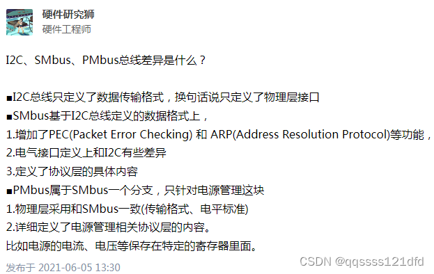
S M B U S , S y s t e m M a n a g e m e n t B u s SMBUS,System\quad Management\quad Bus SMBUS,SystemManagementBus总线协议和 P M B U S , P o w e r M a n a g e m e n t B u s PMBUS,Power\quad Management\quad Bus PMBUS,PowerManagementBus总线协议都是基于 I 2 C I2C I2C总线协议的,只不过在 I 2 C I2C I2C总线协议基于特定的需求加入了特定的命令集以及针对特定应用的扩展,通常情况下 I 2 C I2C I2C总线设备可以和 S M B U S SMBUS SMBUS总线设备以及 P M B U S PMBUS PMBUS总线设备一起使用。下面我们首先看一下知乎上一位小哥的对以上三种总线协议差异性的总结。如图15所示。
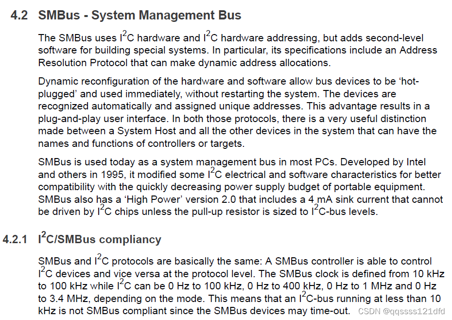
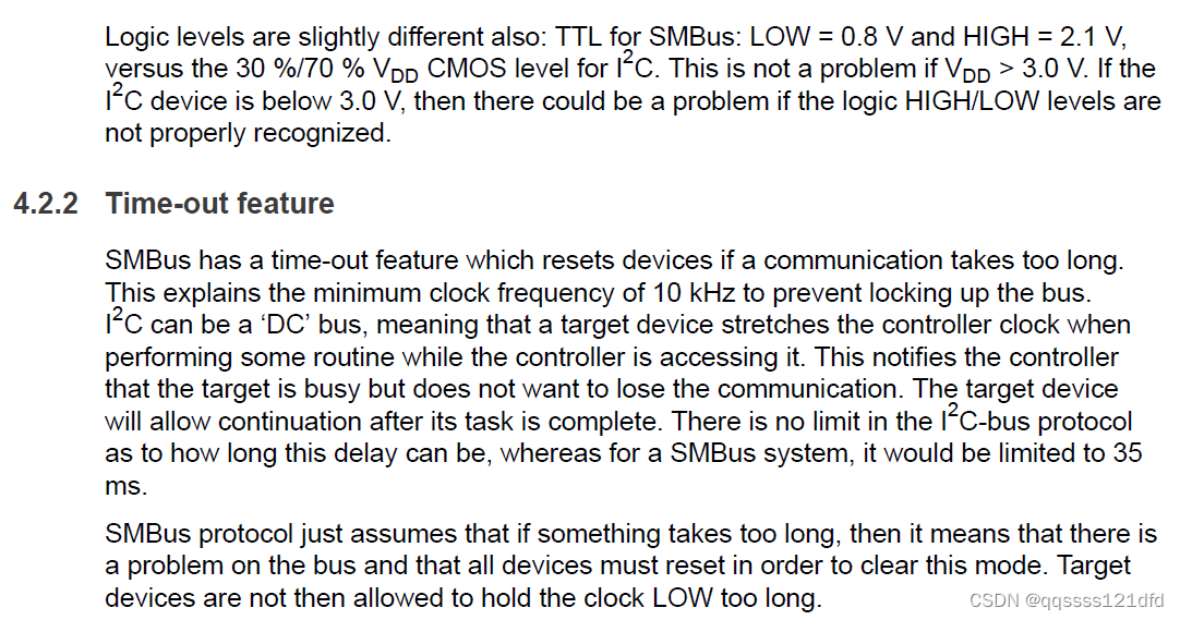
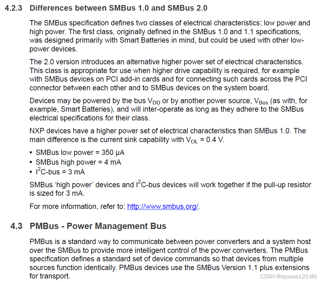
下面我们再来看一下 I 2 C I2C I2C总线协议文档上对 S M B U S SMBUS SMBUS总线协议以及 P M B U S PMBUS PMBUS总线协议的描述,如图16,图17和图18所示。 S M B U S SMBUS SMBUS总线协议包含了一个地址解析协议, A d d r e s s R e s o l u t i o n P r o t o c o l Address\quad Resolution\quad Protocol AddressResolutionProtocol,这个地址解析协议可以用来进行动态地址分配。硬件和软件的动态重新配置可以使得总线设备可以热拔插且立即使用而不用重启系统。设备被自动识别并分配唯一的地址。这个优点的结果就是即插即用的用户接口。
S M B U S SMBUS SMBUS总线中有 m a s t e r master master, s l a v e slave slave和 h o s t host host三种不同类型的设备, s l a v e slave slave设备接收或相应命令, m a s t e r master master设备发送命令,产生时钟信号和终止传输, h o s t host host设备是一种特殊的 m a s t e r master master设备,它给系统 C P U CPU CPU提供接口。 h o s t host host设备同时具备 m a s t e r master master设备和 s l a v e slave slave设备的功能并且支持 h o s t n o t i f y host\quad notify hostnotify协议,系统中最多只有一个 h o s t host host设备,也可以没有 h o s t host host设备。一个设备可以被设计成从来都不是 m a s t e r master master设备,而一直是 s l a v e slave slave设备。一个设备在绝大多数的时间里面可以扮演 s l a v e slave slave设备的角色,但是在某个特定的时刻又可以扮演 m a s t e r master master设备的角色。一个设备也可以被设计成永远都是 m a s t e r master master设备。一个系统 h o s t host host设备的例子是大部分时间扮演 h o s t host host设备的角色,但是却有 s l a v e slave slave设备的功能。 S M B U S SMBUS SMBUS总线协议相比起 I 2 C I2C I2C总线协议主要有以下几方面的不同:
- 电气特性: I 2 C I2C I2C总线协议的逻辑电平一般是 30 % 30\% 30%和 70 % 70\% 70% 的 V D D V_{DD} VDD电压,但是 S M B U S SMBUS SMBUS总线协议的逻辑电平一般是固定的 0.8 V 0.8V 0.8V和 2.1 V 2.1V 2.1V。当然还有其它方面的电气特性的不同,因为我对硬件的东西不是太懂,大家有需要还是去看一起官方的文档说明。
- 工作速率: S M B U S 2.0 SMBUS\quad 2.0 SMBUS2.0的工作速率只有 10 K H Z 10KHZ 10KHZ到 100 K H Z 100KHZ 100KHZ但是 S M B U S 3.0 SMBUS\quad 3.0 SMBUS3.0的工作速率有 10 K H Z 10KHZ 10KHZ到 1 M H Z 1MHZ 1MHZ。 I 2 C I2C I2C的速率理论上可以从 0 H Z 0HZ 0HZ到 5 M H Z 5MHZ 5MHZ。
- 时序: S M B U S SMBUS SMBUS总线协议对某些时序参数进行了明确定义,但是 I 2 C I2C I2C总线协议就没有。比较有代表性的几个参数是, T T I M E O U T T_{TIMEOUT} TTIMEOUT参数规定了时钟信号处于低电平的最长允许时间(35ms), T L O W : S E X T T_{LOW: SEXT} TLOW:SEXT参数规定了所有从机设备堆叠起来的时钟信号处于低电平的最长允许时间(25ms), T L O W : M E X T T_{LOW: MEXT} TLOW:MEXT参数规定了所有主机设备堆叠起来的时钟信号处于低电平的最长允许时间(10ms), I 2 C I2C I2C总线协议就没有类似的规定,时钟信号处于低电平的时间可以时任意的。当然除了这里的三个时序参数外还要其它和 I 2 C I2C I2C总线协议不同的时序参数,这里就不一一列举了,详细请看 S M B U S SMBUS SMBUS总线协议的文档。
- 超时功能:当相应的时钟信号处于低电平的时间超过了 T T I M E O U T T_{TIMEOUT} TTIMEOUT, T L O W : S E X T T_{LOW: SEXT} TLOW:SEXT或 T L O W : M E X T T_{LOW: MEXT} TLOW:MEXT参数的要求时应该复位设备, I 2 C I2C I2C总线协议就没有类似的规定。
- 协议: S M B U S SMBUS SMBUS总线上传输的每一个消息都遵循 S M B U S SMBUS SMBUS协议, S M B U S SMBUS SMBUS协议是定义在 I 2 C I2C I2C总线协议里面数据传输格式的子集。
- A C K ACK ACK和 N A C K NACK NACK信号的使用:详见协议文档。
S
M
B
U
S
SMBUS
SMBUS总线协议定义了设备间通信的协议,在
I
2
C
I2C
I2C协议的基础上增加了超时和数据传输格式标准,但是
S
M
B
U
S
SMBUS
SMBUS总线协议没有定义数据传输的内容。
P
M
B
U
S
PMBUS
PMBUS总线协议是基于
S
M
B
U
S
SMBUS
SMBUS总线协议的,
P
M
B
U
S
PMBUS
PMBUS总线协议定义了一系列命令和数据结构,这些命令和数据结构是电源控制和管理部件所需的。这就使得芯片之间的互操作性不仅在逻辑电平上而是更上一层到达了命令语义的层面。例如
P
M
B
U
S
PMBUS
PMBUS总线协议定义了读取和设置电压大小的命令。这样来看的话,
P
M
B
U
S
PMBUS
PMBUS不是一种新的总线协议而是基于
S
M
B
U
S
SMBUS
SMBUS总线协议的一种高层协议。有需求的话还是得去
P
M
B
U
S
PMBUS
PMBUS总线协议的官网看看。
下面的讲解主要基于
S
M
B
U
S
2.0
SMBUS\quad 2.0
SMBUS2.0的文档,但是现在最新的
S
M
B
U
S
3.0
SMBUS\quad 3.0
SMBUS3.0的文档和
S
M
B
U
S
3.1
SMBUS\quad 3.1
SMBUS3.1的文档都已经出来了,它们主要是在
S
M
B
U
S
2.0
SMBUS\quad 2.0
SMBUS2.0的文档上做了一些更新,有需要的可以自己看看。下面首先看看
S
M
B
U
S
SMBUS
SMBUS中规定的总线协议:
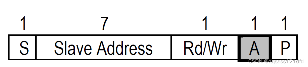
- Quick command:该协议没有数据的发送或接收而是用7bit地址所在的字节里面的读写位来表示对设备的打开或关闭,或者是否进入低功耗模式,如图19所示。
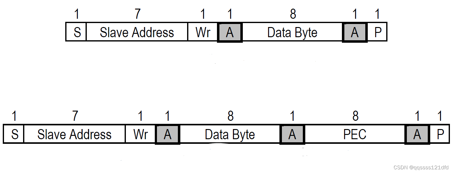
- Send byte:该协议就相当于是主机发送一个字节数据和从机接收一个字节数据。这一个字节的数据可以编码256种不同的命令,或者只是这一个字节的部分比特位被解释为命令。比如这一个字节数据的值可以用来表示设备音量的大小,又或者这一个字节数据的高7位用来表示设备的某个属性,而最低位用来表示是否打开这一属性。如图20所示。
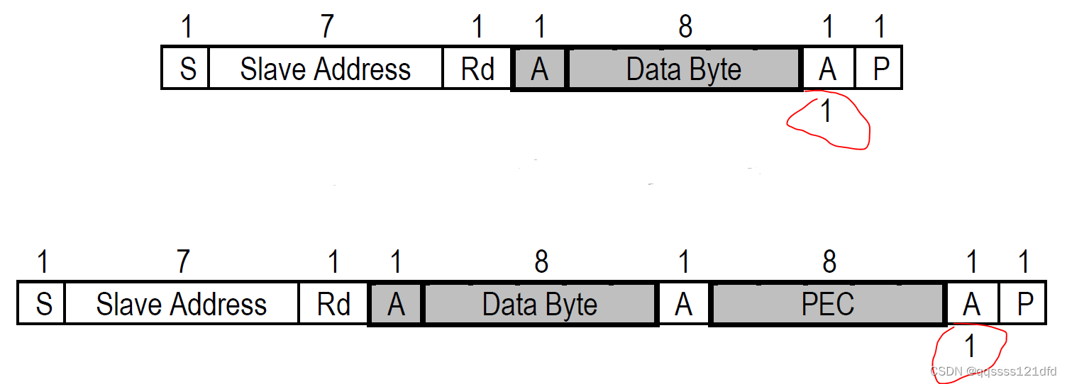
- Receive byte:该协议就相当于是主机接收一个字节数据和从机发送一个字节数据,该协议和 S e n d b y t e Send\quad byte Sendbyte基本一样,但是方向相反,该协议 H O S T HOST HOST可以用来从其它设备中读取所需的信息。当主机已经获取到所需的信息的时候需要给相应的设备一个 N A C K NACK NACK信号来结束通信。如图21所示。
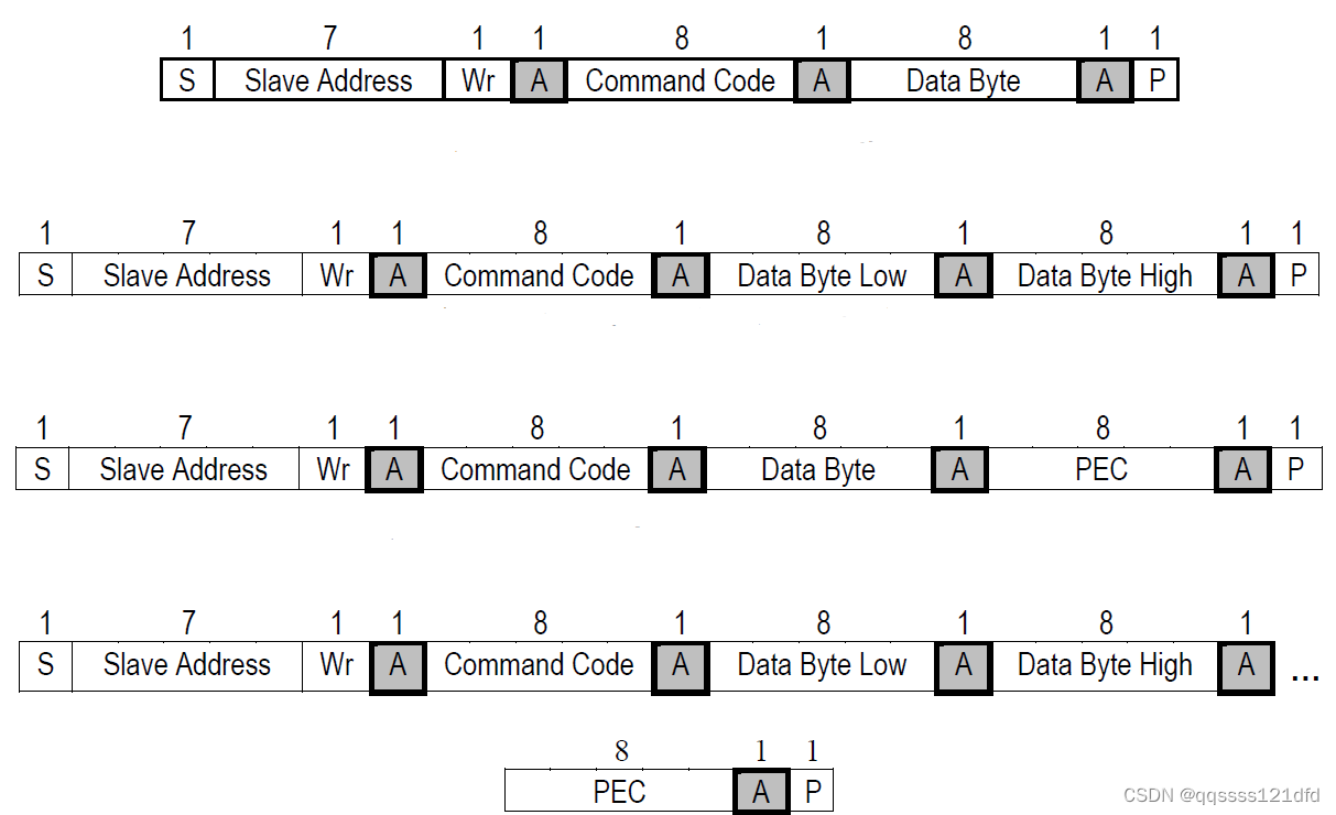
- Write byte/word:该协议发送的第一个数据字节是命令码,第2和第3个数据字节才是实际的数据。如图22所示。
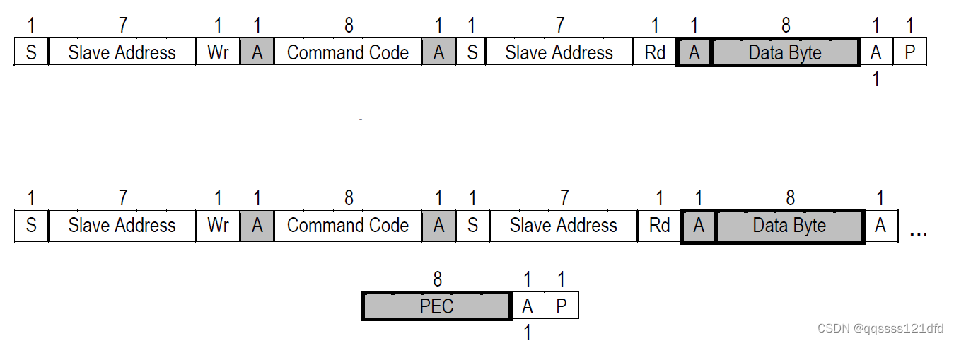
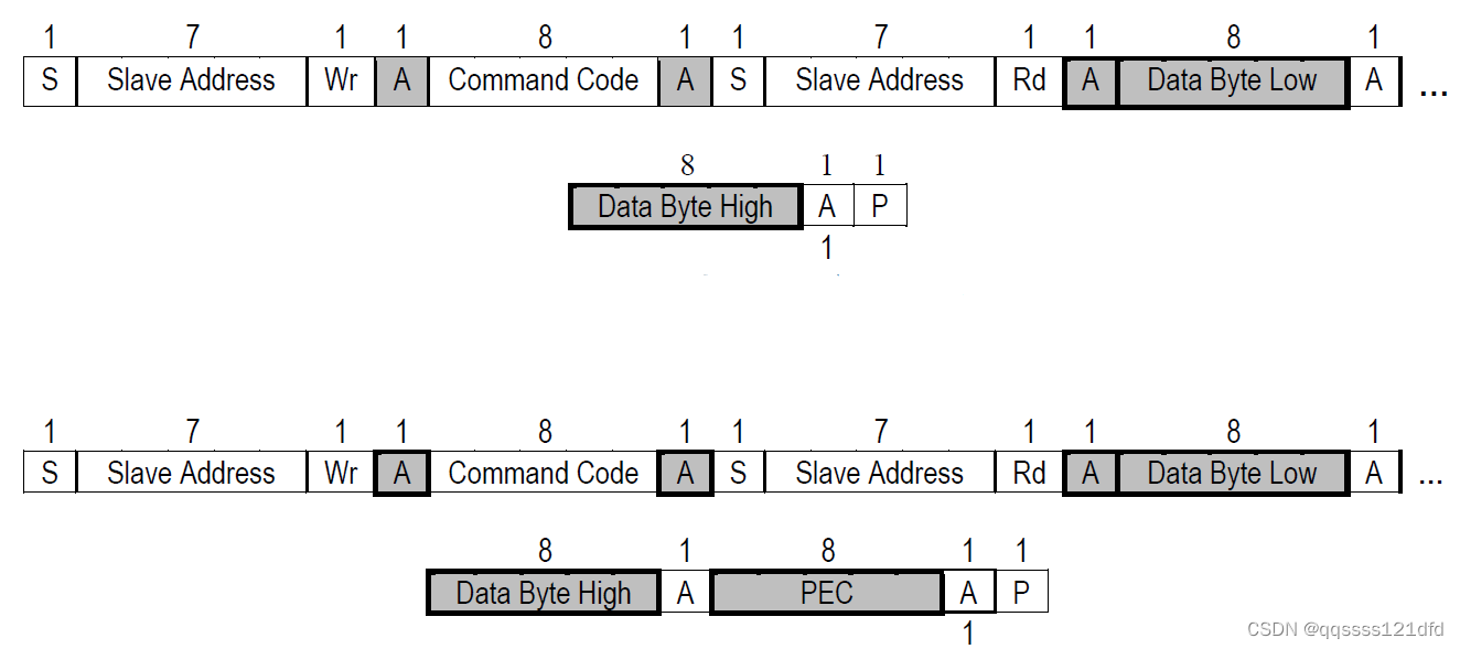
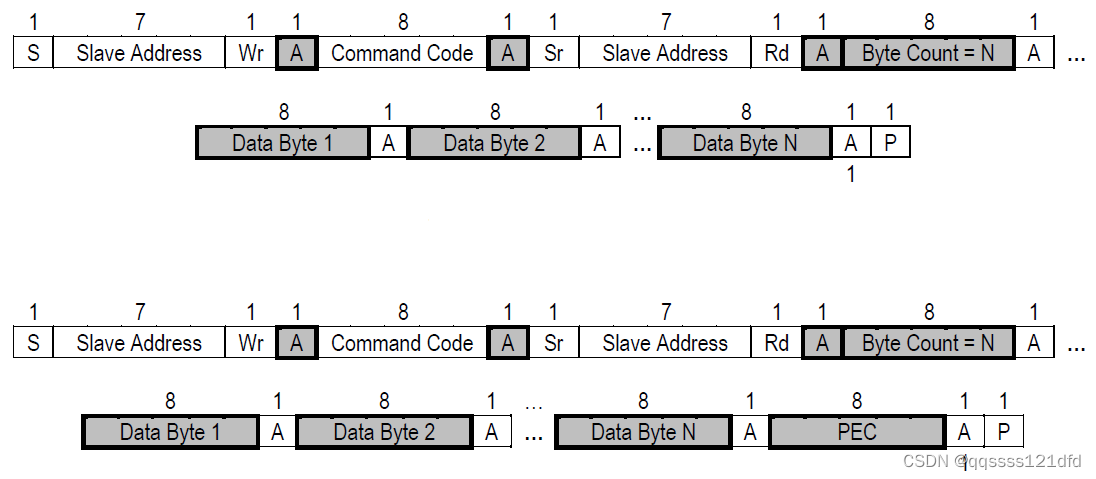
- Read byte/word:该协议要比
W
r
i
t
e
b
y
t
e
/
w
o
r
d
Write\quad byte/word
Writebyte/word稍微复杂一点,
H
O
S
T
HOST
HOST首先要发送设备地址(写操作),然后发送相应的命令码,接着再发送一个
S
T
A
R
T
START
START状态,然后再一次发送设备地址(读操作),最后才是读取一个或两个字节的数据
发送的第一个数据字节是命令码,第2和第3个数据字节才是实际的数据。当主机已经获取到所需的信息的时候需要给相应的设备一个 N A C K NACK NACK信号来结束通信。如图23和图24所示。
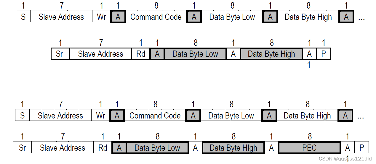
- Process call:该协议 H O S T HOST HOST用来向设备读取特定的数据,至于是什么类型的数据,从机需要根据 H O S T HOST HOST发送的值来确定 。 H O S T HOST HOST首先要发送设备地址(写操作),然后发送相应的命令码,接着再发送用来表明需要获取的设备数据类型的数据。然后再次发送一个 S T A R T START START状态,然后再一次发送设备地址(读操作),最后就是读取一个或两个字节的设备数据。当主机已经获取到所需的信息的时候需要给相应的设备一个 N A C K NACK NACK信号来结束通信。如图25所示。
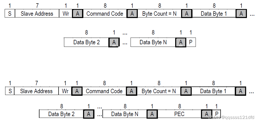
- Block write/read:对于 B l o c k w r i t e Block\quad write Blockwrite协议, H O S T HOST HOST首先要发送设备地址(写操作),然后发送相应的命令码,接着再发送此次要发送的实际数据的个数(假如是20个,那这里发送的字节数据就是0x14),最后再发送20个字节的实际数据。如图26所示。对于 B l o c k r e a d Block\quad read Blockread协议, H O S T HOST HOST首先要发送设备地址(写操作),然后发送相应的命令码,接着再发送一个 S T A R T START START状态,然后发送设备地址(读操作),然后开始接收数据,这里接收到的第一个字节数据的值是设备将会发送的实际字节数据的个数(假如是20个,那这个接收的字节数据的值是0x14,这就表明接下来设备将发送的20个字节数据给 H O S T HOST HOST),最后就是设备发送的实际给 H O S T HOST HOST的数据。当主机已经获取到所需的信息的时候需要给相应的设备一个 N A C K NACK NACK信号来结束通信。如图27所示。还有就是这里读写的实际的数据字节个数的范围是 [ 1 , 32 ] [1,32] [1,32].
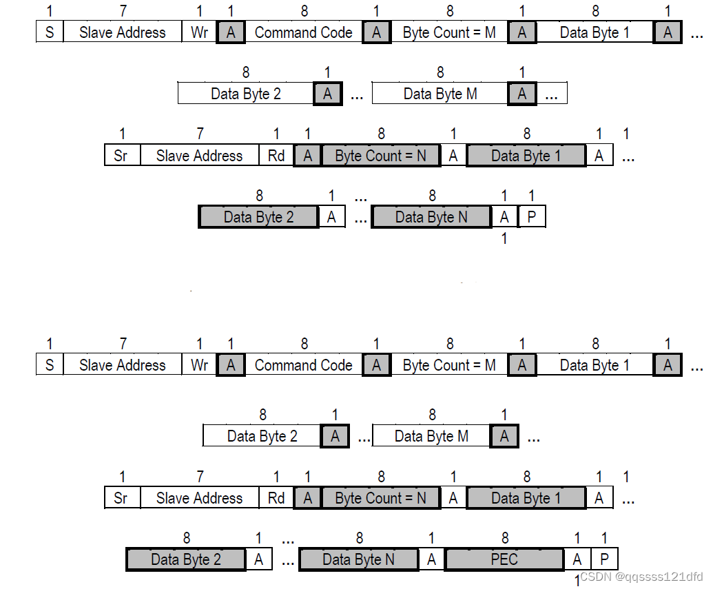
- Block write ->block read process call:该协议是一种两部分的消息,第一部分 H O S T HOST HOST首先要发送设备地址(写操作),然后发送相应的命令码,接着再发送此次要发送的实际数据的个数 M M M(假如是20个,那这里发送的字节数据就是0x14),最后再发送20个字节的实际数据。 H O S T HOST HOST接着再发送一个 S T A R T START START状态 ,然后再发送设备地址(读操作),然后开始接收数据,这里接收到的第一个字节数据的值是设备将会发送的实际字节数据的个数 N N N(假如是20个,那这个接收的字节数据的值是0x14,这就表明接下来设备将发送的20个字节数据给 H O S T HOST HOST),最后就是设备发送的实际给 H O S T HOST HOST的数据。当主机已经获取到所需的信息的时候需要给相应的设备一个 N A C K NACK NACK信号来结束通信。如图28所示。还有就是这里 M ≥ 1 , N ≥ 1 , ( M + N ) ≤ 32 M \geq 1,N \geq 1,(M+N) \leq 32 M≥1,N≥1,(M+N)≤32。
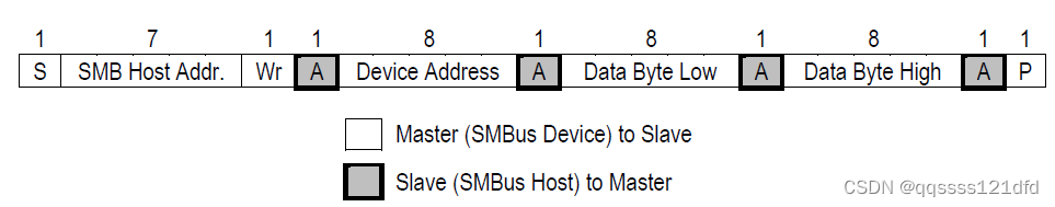
- SMBus host notify protocol:该协议的出现是为了防止进入 s m b u s h o s t smbus\quad host smbushost的数据来自于未知设备且数据的类型也是未知的。该协议是对 W r i t e w o r d Write\quad word Writeword协议的修改, W r i t e w o r d Write\quad word Writeword协议协议中以前发送的命令码在这里被换成是向 s m b u s h o s t smbus\quad host smbushost发起通信的 s m b u s d e v i c e smbus\quad device smbusdevice的地址。这个协议的使用场景是 s m b u s d e v i c e smbus\quad device smbusdevice已经成为了 m a s t e r master master且它想要和此时已经成为 s l a v e slave slave角色的 s m b u s h o s t smbus\quad host smbushost通信。从 s m b u s d e v i c e smbus\quad device smbusdevice到 s m b u s h o s t smbus\quad host smbushost的通信开始于 s m b u s d e v i c e smbus\quad device smbusdevice发送 s m b u s h o s t smbus\quad host smbushost的地址( 0001000 b 0001 000b 0001000b,写操作),接着 s m b u s d e v i c e smbus\quad device smbusdevice再发送自己的地址(这样 s m b u s h o s t smbus\quad host smbushost可以知道是哪个设备在向自己发送该设备的状态信息),最后 s m b u s d e v i c e smbus\quad device smbusdevice发送两个字节的的状态信息给 s m b u s h o s t smbus\quad host smbushost。 s m b u s h o s t smbus\quad host smbushost必须支持 S M B u s h o s t n o t i f y p r o t o c o l SMBus\quad host\quad notify\quad protocol SMBushostnotifyprotocol, s m b u s h o s t smbus\quad host smbushost可以根据需求看是否需要实现 S M B A L E R T SMBALERT SMBALERT信号线。如图29所示。
S M B U S SMBUS SMBUS有两个可选的信号 S M B S U S SMBSUS SMBSUS和 S M B A L E R T SMBALERT SMBALERT:
- S M B S U S SMBSUS SMBSUS:当这个信号为低的时候 S M B S U S SMBSUS SMBSUS总线进入低功耗模式,当这个信号为高的时候 S M B S U S SMBSUS SMBSUS总线进入正常模式。在目前我使用过的 S T M 32 F 103 STM32F103 STM32F103的 I 2 C I2C I2C模块是不支持这个信号的,我这边暂时也没有接触过相关的场景,因此多的就不说了,大家如果有遇到相关的场景可以自己再去看一看 S M B S U S SMBSUS SMBSUS的协议文档。
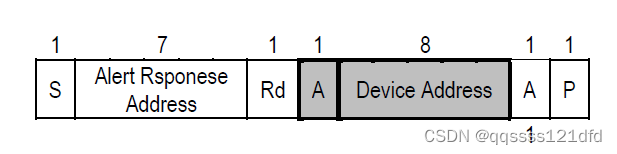
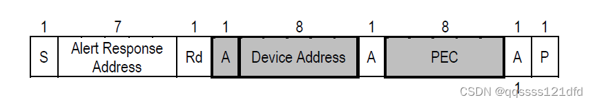
- S M B A L E R T SMBALERT SMBALERT:这个信号在我使用过的 S T M 32 F 103 STM32F103 STM32F103的 I 2 C I2C I2C模块是支持的。从设备可以利用这根信号线来告诉 H O S T HOST HOST它想和 H O S T HOST HOST通信,从设备通过将 S M B A L E R T SMBALERT SMBALERT这根信号线拉低来告诉 H O S T HOST HOST它想和 H O S T HOST HOST通信, H O S T HOST HOST检测到 S M B A L E R T SMBALERT SMBALERT信号的拉低之后通过发送7比特地址 0001100 b 0001 100b 0001100b(读操作)来和相应的设备进行通信,只有那些将 S M B A L E R T SMBALERT SMBALERT信号拉低的设备才会对地址 0001100 b 0001 100b 0001100b进行 A C K ACK ACK(就算此时从设备配置的地址不是 0001100 b 0001 100b 0001100b,从设备也会对地址 0001100 b 0001 100b 0001100b进行 A C K ACK ACK),之后从设备就会把自己本来的地址发送给 H O S T HOST HOST,这里发送的地址放在一个字节的高7位,最低位是0或1都可以。如果有多个从设备拉低了 S M B A L E R T SMBALERT SMBALERT信号,那么此时就会有多个从设备向 H O S T HOST HOST发送自己本身的地址,这时根据仲裁原则,地址值最小的地址将会被发送出去。从设备对 H O S T HOST HOST发送的地址 0001100 b 0001 100b 0001100b进行 A C K ACK ACK之后,应该将 S M B A L E R T SMBALERT SMBALERT信号拉高,否则 H O S T HOST HOST会不断的发送地址 0001100 b 0001 100b 0001100b进行读操作。如图30和图31所示。
S
M
B
U
S
SMBUS
SMBUS总线协议中除了上面介绍的总线协议之外,另外比较重要的一部分是地址解析协议
A
d
d
r
e
s
s
R
e
s
o
l
u
t
i
o
n
P
r
o
t
o
c
o
l
,
A
R
P
Address\quad Resolution\quad Protocol,ARP
AddressResolutionProtocol,ARP。
S
M
B
U
S
SMBUS
SMBUS总线的从设备的地址冲突(可能多个从设备有相同的地址)可以通过动态地给每一个从设备分配一个唯一的地址来解决,这就是通过地址解析协议来实现的。
S
M
B
U
S
A
R
P
M
a
s
t
e
r
SMBUS\quad ARP\quad Master
SMBUSARPMaster负责执行地址解析协议以及给具有
A
d
d
r
e
s
s
R
e
s
o
l
u
t
i
o
n
P
r
o
t
o
c
o
l
,
A
R
P
Address\quad Resolution\quad Protocol,ARP
AddressResolutionProtocol,ARP功能的从设备分配地址。执行地址解析协议的通常是总线中的
h
o
s
t
host
host设备,在在某些情况下也可以是
m
a
s
t
e
r
master
master设备,任何时候总线中只能有一个执行地址解析协议的设备。
为了地址解析协议能够正确的执行,需要有一种机制来区别每一个设备,这时就出现了
U
n
i
q
u
e
D
e
v
i
c
e
I
d
e
n
t
i
f
i
e
r
,
U
D
I
D
Unique\quad Device\quad Identifier ,UDID
UniqueDeviceIdentifier,UDID,这玩意就像是人的身份证号码一样,
U
n
i
q
u
e
D
e
v
i
c
e
I
d
e
n
t
i
f
i
e
r
,
U
D
I
D
Unique\quad Device\quad Identifier ,UDID
UniqueDeviceIdentifier,UDID的长度是128比特,至于其具体的含义,还是大家去看一下
S
M
B
U
S
SMBUS
SMBUS总线协议的文档,因为我没有接触过实际的应用场景,所以这里也不太好讲。
S
M
B
U
S
A
R
P
M
a
s
t
e
r
SMBUS\quad ARP\quad Master
SMBUSARPMaster可以发送通用命令(
g
e
n
e
r
a
l
c
o
m
m
a
n
d
general\quad command
generalcommand)和指向性命令(
d
i
r
e
c
t
e
d
c
o
m
m
a
n
d
directed\quad command
directedcommand)。通用命令可以针对所有的设备,但是需要地址解析过程,指向性命令针对单个特定的设备。
S
M
B
U
S
A
R
P
M
a
s
t
e
r
SMBUS\quad ARP\quad Master
SMBUSARPMaster发送的所有数据包都必须带上
P
E
C
PEC
PEC。在所有
A
R
P
ARP
ARP指令的发送中有两个非常重要的地址,
0001000
b
,
S
M
B
u
s
H
o
s
t
A
d
d
r
e
s
s
0001000b,SMBus\quad Host\quad Address
0001000b,SMBusHostAddress和
1100001
b
,
S
M
B
u
s
D
e
v
i
c
e
D
e
f
a
u
l
t
A
d
d
r
e
s
s
1100 001b,SMBus\quad Device\quad Default\quad Address
1100001b,SMBusDeviceDefaultAddress。
S
M
B
U
S
SMBUS
SMBUS设备分为以下几种类型:
- ARP-capable Device supports all ARP commands with the exception of the optional host
notify command. Slave address is assignable. Device supports both Reset
commands. - Fixed and Discoverable Device supports the Prepare to ARP, directed Get UDID, general Get UDID
and Assign Address commands. Slave address is fixed; device will accept
the Assign Address command but will not allow address reassignment.
Device supports both Reset commands. - Fixed, not Discoverable Device supports the directed Get UDID command. Slave address is fixed.
- Non-ARP-capable Device does not support any ARP commands. Slave address is fixed.
下面我们来看一下 A R P ARP ARP协议的几个命令:
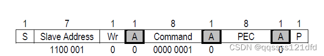
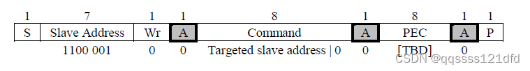
- P r e p a r e t o A R P Prepare\quad to\quad ARP PreparetoARP:这个命令通知所有的设备 S M B U S A R P M a s t e r SMBUS\quad ARP\quad Master SMBUSARPMaster要开始进行 A R P ARP ARP流程了,所有的ARP-capable Device必须 A C K ACK ACK这个命令的数据包的所有字节并且清除它们的 A d d r e s s R e s o l v e d f l a g , A R Address\quad Resolved\quad flag,AR AddressResolvedflag,AR标志位,但是 A d d r e s s V a l i d f l a g , A V Address\quad Valid\quad flag,AV AddressValidflag,AV标志位保持不变,它们也必须马上取消任何挂起的 N o t i f y A R P M a s t e r Notify\quad ARP\quad Master NotifyARPMaster命令。如果 S M B U S A R P M a s t e r SMBUS\quad ARP\quad Master SMBUSARPMaster检测到这个命令数据包的任何一个字节被 N A C K NACK NACK了, S M B U S A R P M a s t e r SMBUS\quad ARP\quad Master SMBUSARPMaster就会判定总线上没有任何的ARP-capable Device。此时 S M B U S A R P M a s t e r SMBUS\quad ARP\quad Master SMBUSARPMaster可能会重新发送 P r e p a r e t o A R P Prepare\quad to\quad ARP PreparetoARP命令,因为前面被 N A C K NACK NACK的字节可能是由于噪音造成的。该命令的数据包如图32所示。
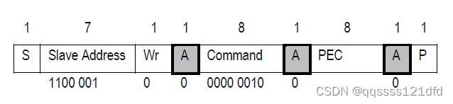
- R e s e t d e v i c e ( g e n e r a l ) Reset\quad device (general) Resetdevice(general):这个命令强制所有的Non-Persistent Slave Address且ARP-capable Device回到它们的初始化状态,它们必须清除 A d d r e s s R e s o l v e d f l a g , A R Address\quad Resolved\quad flag,AR AddressResolvedflag,AR标志位和 A d d r e s s V a l i d f l a g , A V Address\quad Valid\quad flag,AV AddressValidflag,AV标志位,但是如果具有Persistent Slave Address属性的话 A d d r e s s V a l i d f l a g , A V Address\quad Valid\quad flag,AV AddressValidflag,AV标志位保持不变。所有的ARP-capable Device必须 A C K ACK ACK这个命令的数据包的每一个字节。如果 S M B U S A R P M a s t e r SMBUS\quad ARP\quad Master SMBUSARPMaster检测到这个命令数据包的任何一个字节被 N A C K NACK NACK了, S M B U S A R P M a s t e r SMBUS\quad ARP\quad Master SMBUSARPMaster就会判定总线上没有任何的ARP-capable Device。在自身的 U n i q u e D e v i c e I d e n t i f i e r , U D I D Unique\quad Device\quad Identifier ,UDID UniqueDeviceIdentifier,UDID中实现了随机数的ARP-capable Device在接收到这个命令之后必须重新生成随机数。该命令的数据包如图33所示。
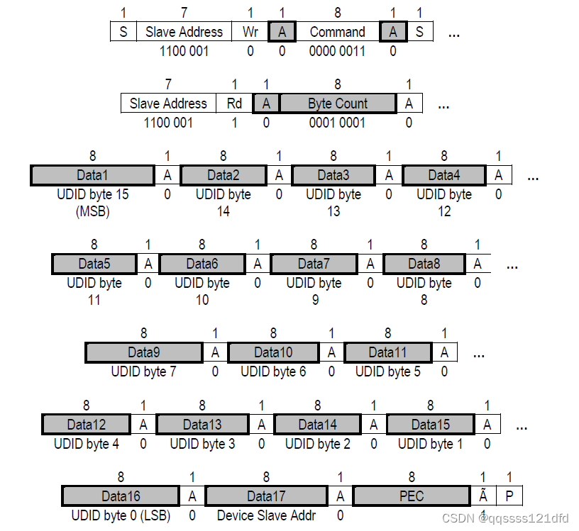
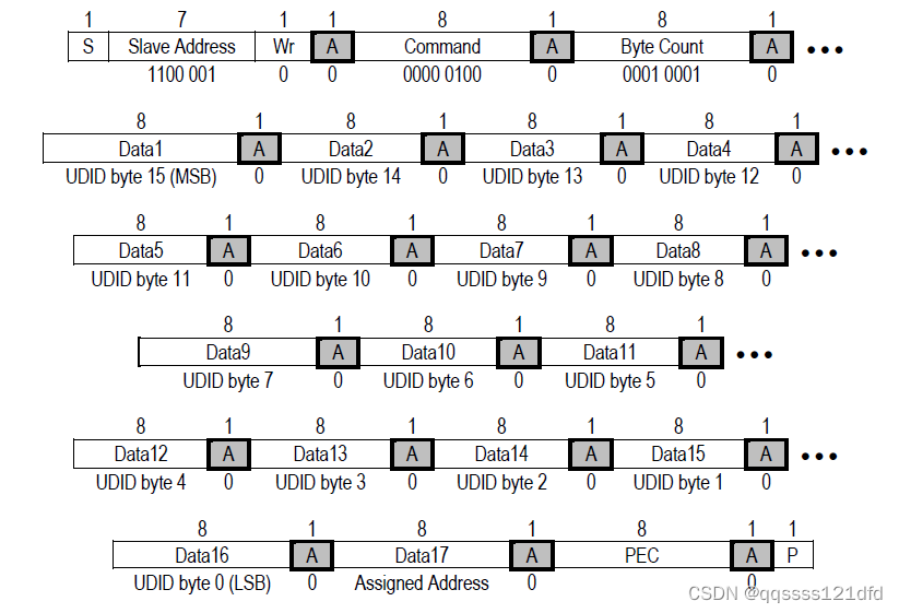
- G e t U D I D ( g e n e r a l ) Get\quad UDID(general) GetUDID(general):这个命令要求ARP-capable Device和Discoverable Device返回它们的 U D I D UDID UDID和地址。如果 S M B U S A R P M a s t e r SMBUS\quad ARP\quad Master SMBUSARPMaster检测到这个命令数据包的前3个字节被 N A C K NACK NACK了, S M B U S A R P M a s t e r SMBUS\quad ARP\quad Master SMBUSARPMaster就会判定总线上没有任何的ARP-capable Device和Discoverable Device,或者所有的*ARP-capable Device**已经被分配了有效的地址。接收到这个命令的设备 A d d r e s s R e s o l v e d f l a g , A R Address\quad Resolved\quad flag,AR AddressResolvedflag,AR标志位和 A d d r e s s V a l i d f l a g , A V Address\quad Valid\quad flag,AV AddressValidflag,AV标志位都保持不变。该命令的数据包如图34所示。
- A s s i g n a d d r e s s Assign\quad address Assignaddress: S M B U S A R P M a s t e r SMBUS\quad ARP\quad Master SMBUSARPMaster通过这个命令来给特定的设备(通过数据包里面的 U D I D UDID UDID来确定是哪一个设备)分配一个地址。如果某个设备发现这个命令的数据包里面的 U D I D UDID UDID和自己的不一样,那么它就会 N A C K NACK NACK这个数据包,如果某个设备发现这个命令的数据包里面的 U D I D UDID UDID和自己的一样,那么它就会将这个数据包里面传输的地址配置为自己的地址且 A d d r e s s R e s o l v e d f l a g , A R Address\quad Resolved\quad flag,AR AddressResolvedflag,AR标志位和 A d d r e s s V a l i d f l a g , A V Address\quad Valid\quad flag,AV AddressValidflag,AV标志位都将会被置位。如果 S M B U S A R P M a s t e r SMBUS\quad ARP\quad Master SMBUSARPMaster检测到这个命令数据包被 N A C K NACK NACK了,那说明这个指定的设备可能不在总线中。但是此时 S M B U S A R P M a s t e r SMBUS\quad ARP\quad Master SMBUSARPMaster也会重新尝试发送 A s s i g n a d d r e s s Assign\quad address Assignaddress数据包,因为 N A C K NACK NACK可能是噪音引起的。
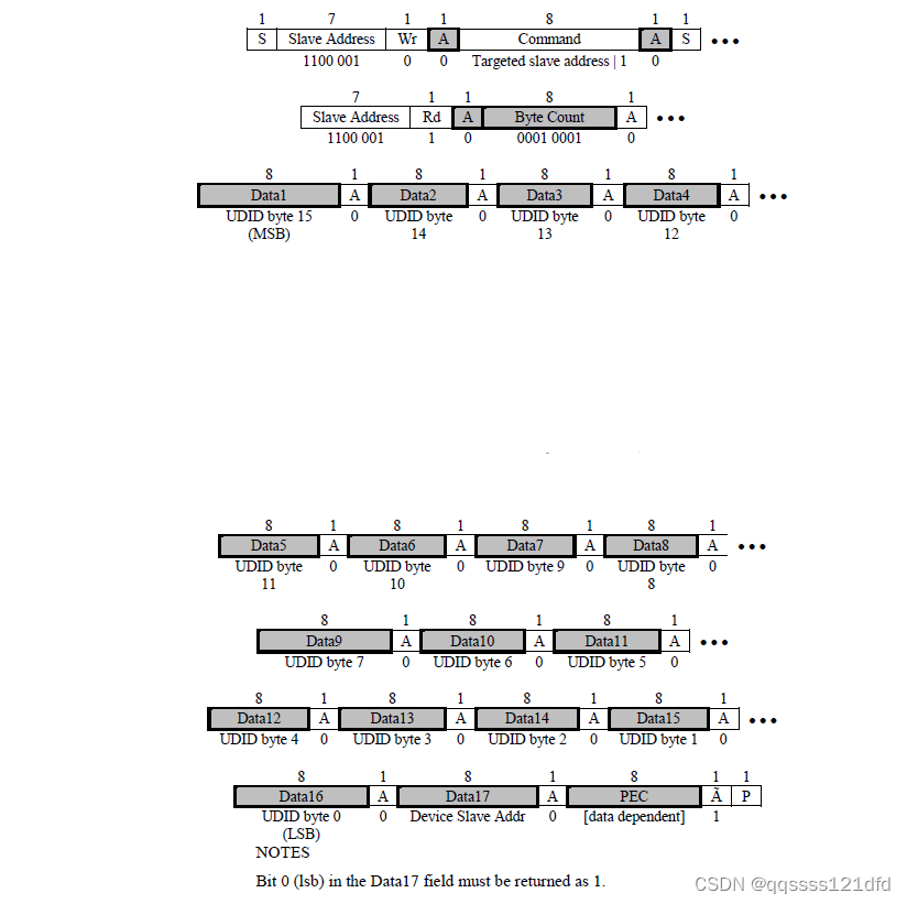
- G e t U D I D ( d i r e c t e d ) Get\quad UDID(directed) GetUDID(directed):这个命令要求特定的ARP-capable Device返回它们的 U D I D UDID UDID。如果 S M B U S A R P M a s t e r SMBUS\quad ARP\quad Master SMBUSARPMaster检测到这个命令数据包的前3个字节被 N A C K NACK NACK了, S M B U S A R P M a s t e r SMBUS\quad ARP\quad Master SMBUSARPMaster就会判定总线上没有任何的ARP-capable Device。接收到这个命令的设备 A d d r e s s R e s o l v e d f l a g , A R Address\quad Resolved\quad flag,AR AddressResolvedflag,AR标志位和 A d d r e s s V a l i d f l a g , A V Address\quad Valid\quad flag,AV AddressValidflag,AV标志位都保持不变。该命令的数据包如图36所示。
- R e s e t d e v i c e ( d i r e c t e d ) Reset\quad device (directed) Resetdevice(directed):这个命令强制一个特定的Non-Persistent Slave Address且ARP-capable Device回到它们的初始化状态,它们必须清除 A d d r e s s R e s o l v e d f l a g , A R Address\quad Resolved\quad flag,AR AddressResolvedflag,AR标志位和 A d d r e s s V a l i d f l a g , A V Address\quad Valid\quad flag,AV AddressValidflag,AV标志位,但是如果具有Persistent Slave Address属性的话 A d d r e s s V a l i d f l a g , A V Address\quad Valid\quad flag,AV AddressValidflag,AV标志位保持不变。如果 S M B U S A R P M a s t e r SMBUS\quad ARP\quad Master SMBUSARPMaster检测到这个命令数据包的任何一个字节被 N A C K NACK NACK了, S M B U S A R P M a s t e r SMBUS\quad ARP\quad Master SMBUSARPMaster就会判定总线上没有使用这个特定地址的的ARP-capable Device。如果这个特定的ARP-capable Device在自身的 U n i q u e D e v i c e I d e n t i f i e r , U D I D Unique\quad Device\quad Identifier ,UDID UniqueDeviceIdentifier,UDID中实现了随机数,那么在接收到这个命令之后必须重新生成随机数。该命令的数据包如图37所示。
-
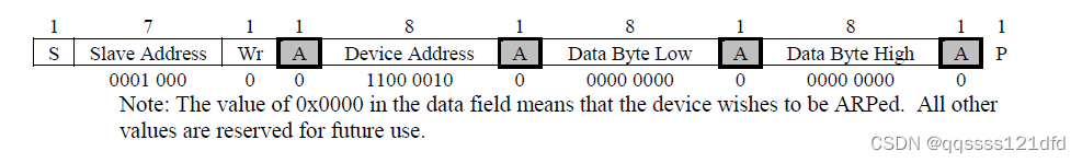
N
o
t
i
f
y
A
R
P
M
a
s
t
e
r
Notify\quad ARP\quad Master
NotifyARPMaster:一个设备通过这个命令通知
S
M
B
U
S
A
R
P
M
a
s
t
e
r
SMBUS\quad ARP\quad Master
SMBUSARPMaster来表明这个设备需要地址解析。该命令的数据包如图38所示。设备可能在一下两种场景下执行这个命令:
- 设备上电
- 当其它设备向这个设备发起读操作的时候,这个设备侦测到了总线冲突
对于 A R P ARP ARP协议的地址分配过程,一般都是当 S M B U S A R P M a s t e r SMBUS\quad ARP\quad Master SMBUSARPMaster进入到了工作状态或者 S M B U S A R P M a s t e r SMBUS\quad ARP\quad Master SMBUSARPMaster检测到了总线上有设备加入或移除,此时 S M B U S A R P M a s t e r SMBUS\quad ARP\quad Master SMBUSARPMaster首先会发送 P r e p a r e t o A R P Prepare\quad to\quad ARP PreparetoARP命令,然后通过 G e t U D I D Get\quad UDID GetUDID命令和 A s s i g n a d d r e s s Assign\quad address Assignaddress命令的发送来实现地址分配的目的。详细的流程还是请大家看一下协议文档,如果有实际的运用场景的话,那就最好不过了。


 741
741

 被折叠的 条评论
为什么被折叠?
被折叠的 条评论
为什么被折叠?
 到【灌水乐园】发言


