


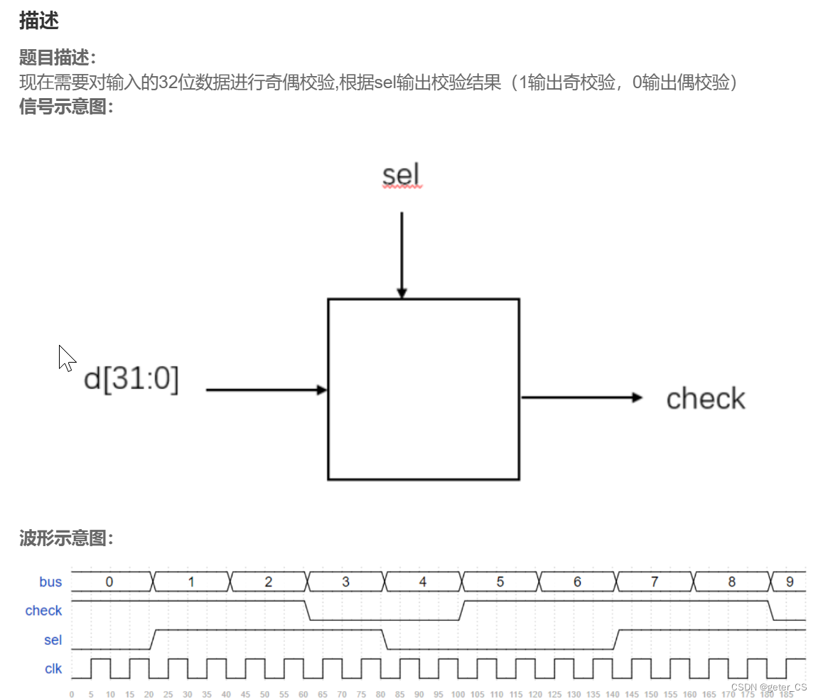
VL3奇偶校验
`timescale 1ns/1ns
module odd_sel(
input [31:0] bus,
input sel,
output check
);
//*************code***********//
assign check=sel?^bus:~^bus;
//*************code***********//
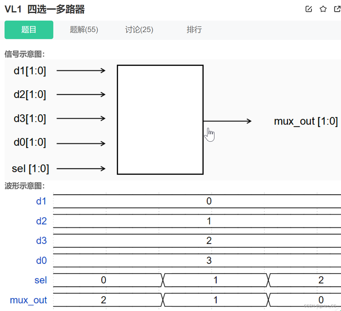
endmoduleVL1 四选一多路器
`timescale 1ns/1ns
module mux4_1(
input [1:0]d1,d2,d3,d0,
input [1:0]sel,
output[1:0]mux_out
);
//*************code***********//
assign mux_out=sel[0]?(sel[1]?3:1):(sel[1]?0:2);
//assign mux_out=sel==0?2:(sel==1?1:(sel==2?0:3));
//*************code***********//
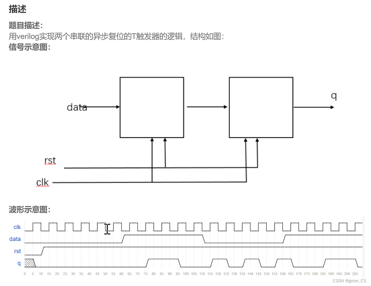
endmoduleVL2 异步复位的串联T触发器
T触发器是在数字电路中,凡在CP时钟脉冲控制下,根据输入信号T取值的不同,具有保持和翻转功能的触发器,即当T=0时能保持状态不变,当T=1时一定翻转的电路。--百度百科
`timescale 1ns/1ns
module Tff_2 (
input wire data, clk, rst,
output reg q
);
//*************code***********//
reg q0;
always@(posedge clk or negedge rst) begin
    if(!rst) begin
        q0<=0;
    end else begin
        case(data)
            'b1:q0<=~q0;
            default: q0<=q0;
        endcase
    end
end

always@(posedge clk or negedge rst) begin
    if(!rst) begin
        q<=0;
    end else begin
        case(q0)
            'b1:q<=~q;
            default: q<=q;
        endcase
    end
end

//*************code***********//
endmodule
真值表:
data q0 q0next q0next q q_next
0 0 0 0 0 0
0 1 1 0 1 1
1 0 1 1 0 1
1 1 0 1 1 0
q0_next<=data^q0
q_next<=data^q1
`timescale 1ns/1ns
module Tff_2 (
input wire data, clk, rst,
output reg q
);
//*************code***********//
reg q0;
always@(posedge clk or negedge rst) begin
if(!rst) begin
q0<=0;
q<=0;
end else begin
q0<=data^q0;
q<=q0^q;
end
end
//*************code***********//
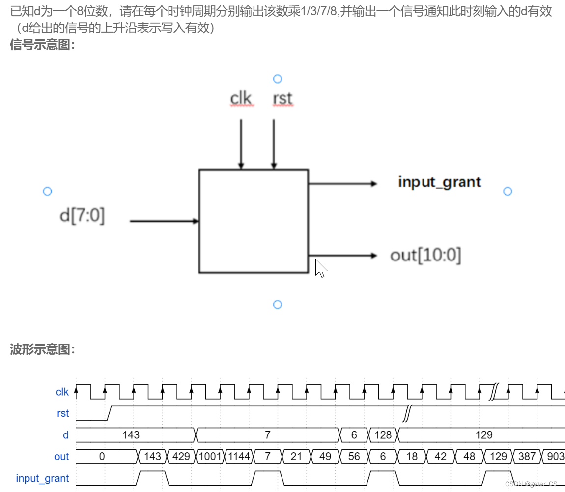
endmoduleVL4 移位运算与乘法
`timescale 1ns/1ns
module multi_sel(
input [7:0]d ,
input clk,
input rst,
output reg input_grant,
output reg [10:0]out
);
//*************code***********//
reg [1:0]count;
reg [7:0] reg_n;
always@(posedge clk or negedge rst) begin
    if(!rst) begin
        out<=0;
        input_grant<=0;
        count<=0;
        reg_n<=0;
    end else begin
        if(count==0) begin
            out<=d*1;
            reg_n<=d;
            input_grant<=1;
            count<=count+1;
        end else if(count==1) begin
            out<=reg_n*3;
            input_grant<=0;
            count<=count+1;
        end else if(count==2) begin
            out<=reg_n*7;
            input_grant<=0;
            count<=count+1;
        end else begin
            out<=reg_n*8;
            input_grant<=0;
            count<=0;
        end
    end
end

//*************code***********//
endmodule
`timescale 1ns/1ns
module multi_sel(
input [7:0]d ,
input clk,
input rst,
output reg input_grant,
output reg [10:0]out
);
//*************code***********//
reg [1:0] CS,NS;
reg [7:0] reg_n;
//state change
always@(posedge clk or negedge rst) begin
if(!rst) begin
CS<='b00;
NS<='b00;
end else begin
CS<=NS;
end
end
//next state
always @(CS or NS)begin
case(CS)
'b00:NS<='b01;
'b01:NS<='b10;
'b10:NS<='b11;
default:NS<='b00;
endcase
end
//output
always @(posedge clk or negedge rst) begin
if(!rst) begin
out<=0;
input_grant<=0;
end else begin
case(CS)
'b00:begin
out<=d;
input_grant<=1;
reg_n<=d;
end
'b01:begin
out<=reg_n*3;
input_grant<=0;
end
'b10:begin
out<=reg_n*7;
input_grant<=0;
end
default:begin
out<=reg_n*8;
input_grant<=0;
end
endcase
end
end
//********


 367
367


 被折叠的 条评论
为什么被折叠?
被折叠的 条评论
为什么被折叠?
 到【灌水乐园】发言


