


ESP32C3启动流程可以分为如下3 个步骤:
- 一级引导程序(PBL):被固化在了ESP32-C3 内部的ROM 中,它会从flash 的0x0 偏移地址处加载二级引导程序至RAM (IRAM & DRAM) 中。
- 二级引导程序(SBL):从flash 中加载分区表和主程序镜像至内存中,主程序中包含了RAM 段和通过flash高速缓存映射的只读段。
- 应用程序(RTOS):APP启动运行,这时RTOS 的调度器和第二个CPU(多核)启动。
一级引导程序(PBL)
PBL固化在ESP32C3芯片内部ROM,无法更改。由于官方没有公开PBL的代码,这里直接参考开发向导的功能介绍。
SoC 复位上电后,CPU 会立即跳转至0x4000_0000地址处,开始执行初始化操作。乐鑫提供了ELF格式的内部固件,以下是ELF头信息:
> riscv32-esp-elf-readelf.exe -h G:\Program\Espressif\tools\esp-rom-elfs\20230113\esp32c3_rev3_rom.elf
ELF Header:
  Magic:   7f 45 4c 46 01 01 01 00 00 00 00 00 00 00 00 00
  Class:                             ELF32
  Data:                              2's complement, little endian
  Version:                           1 (current)
  OS/ABI:                            UNIX - System V
  ABI Version:                       0
  Type:                              EXEC (Executable file)
  Machine:                           RISC-V
  Version:                           0x1
  Entry point address:               0x40000000
  Start of program headers:          52 (bytes into file)
  Start of section headers:          553332 (bytes into file)
  Flags:                             0x1, RVC, soft-float ABI
  Size of this header:               52 (bytes)
  Size of program headers:           32 (bytes)
  Number of program headers:         28
  Size of section headers:           40 (bytes)
  Number of section headers:         75
  Section header string table index: 74
PBL开机日志:
ESP-ROM:esp32c3-api1-20210207
Build:Feb  7 2021
rst:0x15 (USB_UART_CHIP_RESET),boot:0xc (SPI_FAST_FLASH_BOOT)
Saved PC:0x4004c634
0x4004c634: uart_rx_readbuff in ROM

SPIWP:0xee
mode:DIO, clock div:1
load:0x3fcd5820,len:0x1710
load:0x403cc710,len:0x968
load:0x403ce710,len:0x2f9c
entry 0x403cc710
//上面是PBL日志,后面是SBL日志
I (15) boot: ESP-IDF HEAD-HASH-NOTFOUND 2nd stage bootloader
I (15) boot: compile time Jan 23 2024 19:23:22
I (15) boot: chip revision: v0.4
复位向量调用的启动代码会根据GPIO_STRAP_REG 寄存器的值来确定ESP32-C3 的启动模式,该寄存器保存着复位后bootstrap 引脚的电平状态。bootstrap引脚包括:
• 芯片启动模式– GPIO2、GPIO8 和GPIO9
• ROM 代码日志打印– GPIO8 (默认开启并从USB Serial打印,GPIO8任意值)
从上表可知,bootstrap引脚决定是否进入下载模式或SPI启动模式。
1)下载模式
用户可通过UART0 或USB 接口将代码下载至flash 中,或将程序加载到SRAM 并在SRAM 中运行程序。
下面几个eFuse 可用于控制启动模式的具体行为:
- EFUSE_DIS_FORCE_DOWNLOAD
如果此eFuse 设置为0(默认),软件可通过设置RTC_CNTL_FORCE_DOWNLOAD_BOOT,触发CPU 复位,将芯片启动模式强制从SPI Boot 模式切换至Download Boot 模式;如果此eFuse 设置为1,则禁用RTC_CNTL_FORCE_DOWNLOAD_BOOT。 - EFUSE_DIS_DOWNLOAD_MODE
如果此eFuse 设置为1,则禁用Download Boot 模式。 - EFUSE_ENABLE_SECURITY_DOWNLOAD
如果此eFuse 设置为1,则在Download Boot 模式下,只允许读取、写入和擦除明文flash,不支持SRAM或寄存器操作。如已禁用Download Boot 模式,请忽略此eFuse。
2)SPI启动模式
CPU 通过从SPI flash 中读取程序来启动系统。SPI Boot 模式可进一步细分为以下两种启动方式:
- 常规flash 启动方式:支持安全启动,程序运行在RAM 中
- 直接启动方式:不支持安全启动,程序直接运行在flash 中。如需使能这一启动方式,请确保下载至flash的bin 文件其前两个字(地址:0x42000000)为0xaedb041d。
SoC复位的原因会被保存于寄存器RTC_CNTL_RESET_CAUSE_PROCPU中,数值定义如下: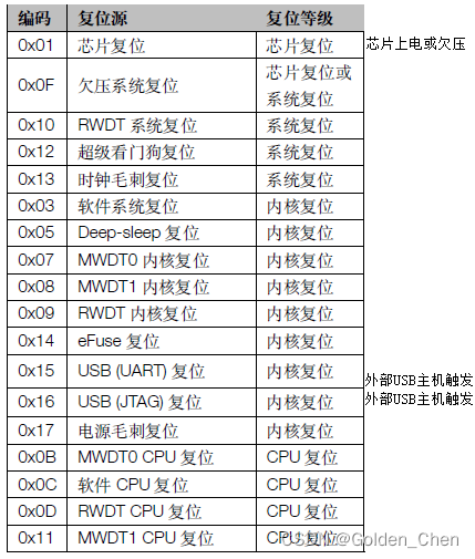
CPU在复位后可读取该值,根据不同的复位原因,程序会执行不同的操作:
(a) 深度睡眠模式复位
深度睡眠模式下,芯片的ROM 和RAM 均将断电,因此在唤醒时SPI 启动(从flash 复制数据)所需时间更长,而RTC 快速内存处于上电状态。因此,为了加速芯片唤醒过程,用户可以将一些代码规模不大(即小于8 KB 的“deep sleep wake stub” )写入RTC 快速内存,并将入口地址写入寄存器RTC_CNTL_STORE6_REG,将RTC 快速内存的CRC 码保存到寄存器RTC_CNTL_STORE7_REG。
当CPU 开启时,开始进行ROM 解包和部分初始化工作。此后,再次计算RTC 快速内存的CRC 码。如果与寄存器RTC_CNTL_STORE7_REG中保存的结果一致,则CPU 跳转至RTC 快速内存的入口地址;否则,运行SoC上电复位的启动流程。
(b) 上电复位、软件SoC 复位、看门狗SoC 复位等
CPU 复位后,PBL引导程序从SPI flash加载SBL引导程序,然后从SBL头部找到程序入口地址并跳转运行,进入SBL引导程序。
IDF系统软件定义了11种复位原因,见代码定义项。
FILE: \components\esp_system\include\esp_system.h
/**
 * @brief Reset reasons
 */
typedef enum {
    ESP_RST_UNKNOWN,    //!< Reset reason can not be determined
    ESP_RST_POWERON,    //!< Reset due to power-on event
    ESP_RST_EXT,        //!< Reset by external pin (not applicable for ESP32)
    ESP_RST_SW,         //!< Software reset via esp_restart
    ESP_RST_PANIC,      //!< Software reset due to exception/panic
    ESP_RST_INT_WDT,    //!< Reset (software or hardware) due to interrupt watchdog
    ESP_RST_TASK_WDT,   //!< Reset due to task watchdog
    ESP_RST_WDT,        //!< Reset due to other watchdogs
    ESP_RST_DEEPSLEEP,  //!< Reset after exiting deep sleep mode
    ESP_RST_BROWNOUT,   //!< Brownout reset (software or hardware)
    ESP_RST_SDIO,       //!< Reset over SDIO
} esp_reset_reason_t;
二级引导程序(SBL)
ESP-IDF的二级引导程序(SBL)主要实现了以下的功能:
增加flash 分区的灵活性(使用分区表);
方便实现flash 加密;
安全引导;
空中升级(OTA) 。
SBL引导固件被烧录于SPI Flash 的0x0000_0000偏移地址处,默认分区大小限制在32KB(见宏CONFIG_PARTITION_TABLE_OFFSET)。其主要源码在ESP-IDF \ component下的子目录bootloader\、bootloader_support\,还有其他被引用的组件,所涉及到的组件可查看编译日志,或直接查看编译结果的子目录情况: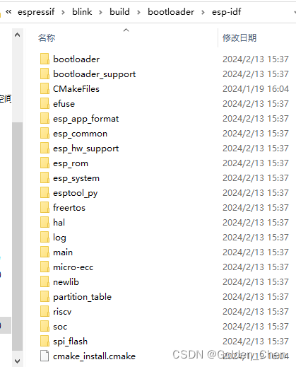
SBL程序入口 是call_start_cpu0()函数,而该函数结构清晰,内部的步骤,很直观展示SBL的运行流程,分为3个阶段:
- 初始化阶段
- 分区选择阶段
- 镜像加载阶段
File: components\bootloader\subproject\main\bootloader_start.c
void __attribute__((noreturn)) call_start_cpu0(void)
{
    // (0. Call the before-init hook, if available)
    if (bootloader_before_init) {
        bootloader_before_init();
    }

    // 1. Hardware initialization
    if (bootloader_init() != ESP_OK) {
        bootloader_reset();
    }

    // (1.1 Call the after-init hook, if available)
    if (bootloader_after_init) {
        bootloader_after_init();
    }

#ifdef CONFIG_BOOTLOADER_SKIP_VALIDATE_IN_DEEP_SLEEP
    // If this boot is a wake up from the deep sleep then go to the short way,
    // try to load the application which worked before deep sleep.
    // It skips a lot of checks due to it was done before (while first boot).
    bootloader_utility_load_boot_image_from_deep_sleep();
    // If it is not successful try to load an application as usual.
#endif

    // 2. Select the number of boot partition
    bootloader_state_t bs = {0};
    int boot_index = select_partition_number(&bs);
    if (boot_index == INVALID_INDEX) {
        bootloader_reset();
    }

    // 3. Load the app image for booting
    bootloader_utility_load_boot_image(&bs, boot_index);
}
1)初始化阶段
--> bootloader_init(void) : // 步骤1. Hardware initialization
    bootloader_hardware_init();
    bootloader_ana_reset_config();
    bootloader_init_mem();
    bootloader_clear_bss_section();
    bootloader_console_init();
    bootloader_init_spi_flash()
    bootloader_config_wdt();     // config WDT
    bootloader_enable_random();  // enable RNG early entropy source
2)分区选择阶段
-->select_partition_number(&bs)      // 步骤2. Select the number of boot partition
    bootloader_utility_load_partition_table(bs) // (1) Load partition table
    selected_boot_partition(bs)                 // (2) Select the number of boot partition
     -->bootloader_utility_get_selected_boot_partition(bs)
           return FACTORY_INDEX; // 如果未设置OTA分区,则返回FACTORY
           read_otadata()  // 读取ota_info分区,获得OTA分区的配置信息
           bootloader_common_get_active_otadata(otadata)
           write_otadata() //若使能APP回滚机制,OTA机制根据状态来更新ota_info分区的数据
           update_anti_rollback() //若使能防回滚机制,保证固件版本不会回落到低版本
3)镜像加载阶段
-->bootloader_utility_load_boot_image(&bs, boot_index);  // 步骤3. Load the app image for booting
    try_load_partition(&bs->test, &image_data)
     -->bootloader_load_image(partition, data) --> image_load(mode, part, data)
           process_image_header(data, part->offset...)
           process_segments(data, silent...)
           process_checksum(sha_handle, checksum_word...)
           process_appended_hash_and_sig(data, part->offset...)
           verify_secure_boot_signature(sha_handle, data...)
           bootloader_sha256_finish(sha_handle, NULL);
           should_load(load_addr)
    load_image(&image_data);
     -->esp_secure_boot_v2_permanently_enable(image_data);
           esp_efuse_batch_write_begin();   /* Batch all efuse writes at the end of this function */
           esp_efuse_batch_write_commit();
     -->esp_secure_boot_generate_digest()
           esp_image_verify_bootloader_data(&bootloader_data);
           secure_boot_generate(image_len)
     -->esp_flash_encrypt_init();
     -->esp_flash_encrypt_contents();
     -->esp_flash_encrypt_enable();
     -->unpack_load_app(image_data); // 加载APP程序的代码、数据段到RAM,配置MMU映射并使能Cache
         set_cache_and_start_app(drom_addr, .......data->image.entry_addr);
          --> mmu_hal_map_region(0, MMU_TARGET_FLASH0, drom_load_addr_aligned....)
          --> mmu_hal_map_region(0, MMU_TARGET_FLASH0, irom_load_addr_aligned....)
          --> cache_ll_l1_enable_bus(0, bus_mask);     //Enable corresponding buses
          --> cache_hal_enable(CACHE_TYPE_ALL);    //Enable Cache
          --> ESP_LOGD(TAG, "start: 0x%08"PRIx32, entry_addr);
          --> entry_t entry = ((entry_t) entry_addr);    // entry_addr = data->image.entry_addr
          --> (*entry)();  //跳转到APP应用程序中


 5582
5582


 被折叠的 条评论
为什么被折叠?
被折叠的 条评论
为什么被折叠?
 到【灌水乐园】发言


