


 Write Booster是提高UFS存储设备写入速度的技术,利用SLC Cache原理。该功能通过配置部分TLC NAND为SLC NAND作为写缓冲区,提升写入性能。设备支持两种工作模式:LU专用缓冲区和共享缓冲区,其大小可配置。Write Booster的启用、缓冲区大小、用户空间配置以及刷新操作由特定的设备标志和主机命令控制。在realme方案中,Write Booster的刷新主要在设备进入休眠状态时进行。
Write Booste是UFS3.1和UFS2.2新增的Feature, 也有叫做Turbo Write的,其实这个就是SSD上已经广泛使用的SLC Cache技术, 可以显著提高写入速度, 此技术已在存储设备厂商和手机厂商中运用了。
以下是协议里面关于Write Booster的介绍:
13.4.14 WriteBooster
13.4.14.1 Overview
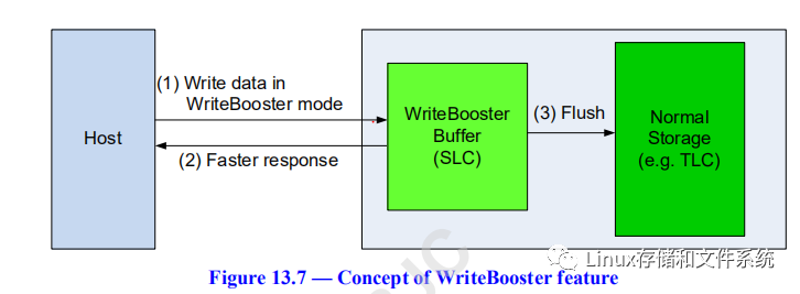
The write performance of TLC NAND is considerably lower than SLC NAND because the logically defined TLC bits require more programming steps and have higher error correction probability. To improve the write performance, part of the TLC NAND (normal storage) is configured as SLC NAND and used as write buffer, temporarily or permanently. Using SLC NAND as a WriteBooster Buffer enables the write request to be processed with lower latency and improves the overall write performance. Some portions of TLC NAND allocated for the user area are assigned as the WriteBooster Buffer. The data written in the WriteBooster Buffer can be flushed into TLC NAND storage by an explicit host command or implicitly while in hibernate (HIBERN8) state. Technologies other than TLC and SLC NAND may be used as normal storage and WriteBooster Buffer.
Bit[8] of dExtendedUFSFeaturesSupport indicates if the device supports the WriteBooster feature. There are two WriteBooster mode of operations: “LU dedicated buffer” mode and “shared buffer” mode. In the “LU dedicated buffer” mode, the WriteBooster Buffer is dedicated to a logical unit, while in the “shared buffer” mode all logical units share the same WriteBooster Buffer except well-known logical units. bSupportedWriteBoosterBufferTypes indicates which modes are supported by the device. In both WriteBooster mode of operations, the WriteBooster Buffer size is configurable.There are two user space configuration options: “user space reduction” and “preserve user space”. With the “user space reduction”, the WriteBooster Buffer reduces the total configurable user space; while with the “preserve user space”, the total space is not reduced.The WriteBooster feature is enabled when fWriteBoosterEn flag is set to one.bAvailableWriteBoosterBufferSize attribute indicates the available space in the WriteBooster Buffer. An exception event is triggered when there is the need to flush the WriteBooster Buffer: bit[5] of wExceptionEventStatus is set to indicate that data in WriteBooster Buffer should be flushed to normal storage.
There are two flags for controlling the WriteBooster Buffer flush operation. fWriteBoosterBufferFlushEn flag enables the flush operation: when it is set to one, the device shall flush the WriteBooster Buffer. fWriteBoosterBufferFlushDuringHibernate enables the flush operation during hibernate: the device initiates a WriteBooster Buffer flush operation whenever the link enters in the hibernate state.bWriteBoosterBufferFlushStatus attribute provides the flush operation status, while bWriteBoosterBufferLifeTimeEst attribute indicates the estimated lifetime of the WriteBooster Buffer.
13.4.14.2 WriteBooster configuration
Bit[8] of dExtendedUFSFeaturesSupport indicates if the device supports the WriteBooster feature. If the device does not support this feature, a query request that attempts to set a WriteBooster parameter in a Configuration Descriptor to a value different from zero shall fail, and the Query Response field in QUERY RESPONSE UPIU shall be set to “General Failure”.The WriteBooster Buffer can be configured in “LU dedicated buffer” mode or “shared buffer” mode according to the device capability. bSupportedWriteBoosterBufferTypes indicates which modes are supported by the device.If bWriteBoosterBufferPreserveUserSpaceEn is set to 00h, the WriteBooster Buffer reduces the total user space that can be configured at provisioning. The amount of the reduction can calculated multiplying the WriteBooster Buffer size by the value indicated by bWriteBoosterBufferCapAdjFac. For example, the bWriteBoosterBufferCapAdjFac value for a TLC NAND storage device with a SLC NAND WriteBooster Buffer is 3; therefore, the total user capacitity that can be configured is reduced by 3 × WriteBoosterBufferCapacity.Setting bWriteBoosterBufferPreserveUserSpaceEn to 01h avoids the reduction of the total user space that can be configured at provisioning, but it may result in lower performance, see Error! Reference source not found..LU dedicated buffer modeIf the device supports the “LU dedicated buffer” mode, this mode is configured by setting bWriteBoosterBufferType to 00h. The logical unit WriteBooster Buffer size is configured by setting the dLUNumWriteBoosterBufferAllocUnits field of the related Unit Descriptor. Only a value greater than zero enables the WriteBooster feature in the logical unit. When bConfigDescrLock attribute is set to 01h, logical unit configuration can no longer be changed.The maximum number of supported WriteBooster Buffers is defined in the bDeviceMaxWriteBoosterLUs parameter of the Geometry Descriptor. bDeviceMaxWriteBoosterLUs is 01h, therefore the WriteBooster Buffer can be configured in only one logical unit.Figure 13.7 shows an example of device configuration with a 2 GB WriteBooster Buffer.
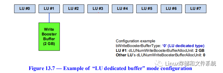
The WriteBooster Buffer is available only for the logical units from 0 to 7 which are configured as “normal memory type” (bMemoryType = 00h) and “not Boot well known logical unit” (bBootLunID = 00h), otherwise the Query Request shall fail and the Query Response field shall be set to “General Failure”.Shared buffer modeIf the device supports the “shared buffer” mode, this mode is configured by setting bWriteBoosterBufferType to 01h. The WriteBooster Buffer size is configured by setting the dNumSharedWriteBoosterBufferAllocUnits field of the Device Descriptor. Figure 13.8 shows an example of device configuration with a 2 GB WriteBooster Buffer.
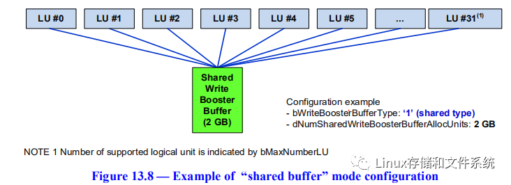
Note that, if bWriteBoosterBufferType is set to 01h but dNumSharedWriteBoosterBufferAllocUnits is set to zero, the WriteBooster feature is disabled.
13.4.14.3 Writing data to WriteBooster Buffer
If the fWriteBoosterEn flag is set to zero, data written to any logical unit is written in normal storage.If the fWriteBoosterEn flag is set to one and the device is configured in “shared buffer” mode, data written to any logical unit is written in the shared WriteBooster Buffer.If the fWriteBoosterEn flag is set to one and the device is configured in “LU dedicated buffer” mode, data written to the logical unit configured to use a dedicated buffer is written in the logical unit WriteBooster Buffer. Data written to any logical unit not configured to use a dedicated buffer is written in normal storage.Writes to the WriteBooster Buffer may decrease the lifetime and the availability of the WriteBooster Buffer.In the “LU dedicated buffer” mode, the device may write data from other LUs to the WriteBooster Buffer in case there are multiple pending commands while fW
 最低0.47元/天 解锁文章


 145
145

 被折叠的 条评论
为什么被折叠?
被折叠的 条评论
为什么被折叠?
 到【灌水乐园】发言


