


STM32 低功耗停机模式(STOP)管脚事件(EVENT)唤醒实现及优化
1. 介绍
STM32具有多种低功耗模式,当前以STM32L4系列的低功耗模式最为丰富,此处基于STM32L476和STM32CUBEIDE环境介绍停机模式(STOP)管脚事件唤醒的实现(HAL库)。STOP模式只是停止代码执行,唤醒(其实是continue的作用)后继续执行后面的代码,而不是重启之后从初始代码开始执行。
2. 低功耗模式
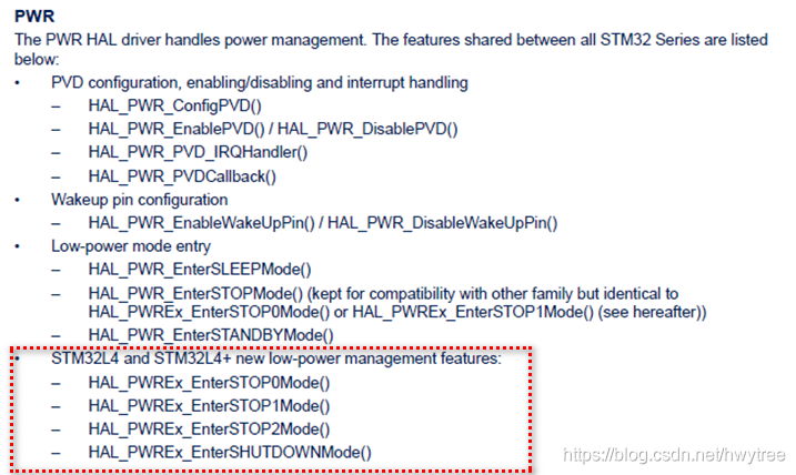
STM32L4的低功耗模式,相比其它系列的芯片,多了几种:
三种STOP模式的区别,可以参考文档:RM0351 Reference manual
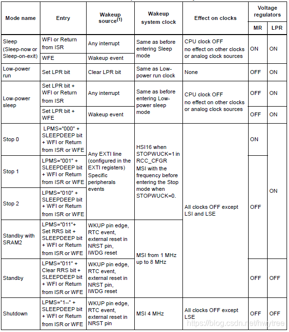
STM32L4系列各种低功耗模式的特性总结如下:
3. 管脚事件配置
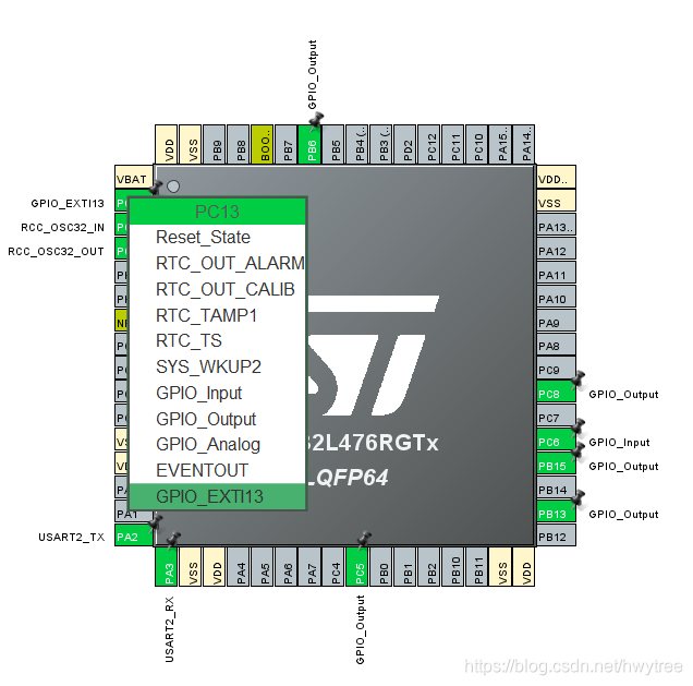
STOP模式可以通过通用管脚中断(Interrupt)或事件(Event)的方式唤醒,这里介绍通用管脚事件唤醒的方式, 选择一个GPIO管脚进行配置,这里用PC13作为唤醒源。
设置PC13为GPIO_EXTI方式:
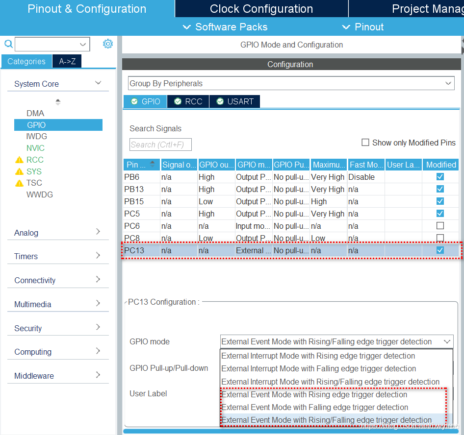
为PC13选择其中一种事件触发方式,包括上升沿触发,下降沿触发和电平变化触发(即上升沿下降沿都触发):
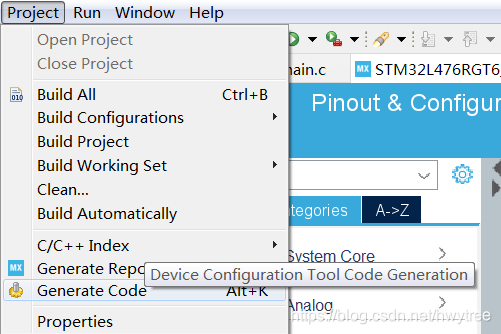
保存后生成代码:
4. STOP模式进入及事件唤醒
通过HAL库函数可进入STOP模式,其中库函数有一个参数,指定唤醒时的来源,有两个可选:PWR_STOPENTRY_WFI 和 PWR_STOPENTRY_WFE, 分别对应管脚中断唤醒和管脚事件唤醒,这里我们用PWR_STOPENTRY_WFE,即管脚事件唤醒。
如果要进入STOP0模式,实施下面代码:
HAL_PWREx_EnterSTOP0Mode(PWR_STOPENTRY_WFE);
SystemClock_Config();
如果要进入STOP1模式,实施下面代码:
HAL_PWREx_EnterSTOP1Mode(PWR_STOPENTRY_WFE);
SystemClock_Config();
如果要进入STOP2模式,实施下面代码:
HAL_PWREx_EnterSTOP2Mode(PWR_STOPENTRY_WFE);
SystemClock_Config();
在执行到上述代码时,MCU就进入了STOP状态,等待管脚上发生信号变化产生的事件唤醒。唤醒后要先进行时钟系统的恢复,即执行SystemClock_Config()初始化时钟配置函数。然后继续执行后面的代码。
5. STOP模式进入及事件唤醒的优化
在STOP进入函数参数为PWR_STOPENTRY_WFE时,并不只是管脚事件可以唤醒,管脚中断也可以唤醒,当设计中存在多种中断源,包括调试器中断和其它管脚中断等,这些中断不是想用于唤醒STOP状态时,此时就需要增加必要的设计,实现:
- 当指定的管脚事件产生时,唤醒STOP状态;
- 非指定的中断源产生中断时不能唤醒STOP状态。
实现方式为在进入STOP状态前,加入中断关闭代码,在事件唤醒STOP状态后,加入打开中断代码,从而在进入STOP状态后,只有指定的管脚事件可以唤醒。
在进入STOP0模式时,采用如下代码:
__disable_irq();
HAL_PWREx_EnterSTOP0Mode(PWR_STOPENTRY_WFE);
__enable_irq();
SystemClock_Config();
在进入STOP1模式时,采用如下代码:
__disable_irq();
HAL_PWREx_EnterSTOP1Mode(PWR_STOPENTRY_WFE);
__enable_irq();
SystemClock_Config();
在进入STOP2模式时,采用如下代码:
__disable_irq();
HAL_PWREx_EnterSTOP2Mode(PWR_STOPENTRY_WFE);
__enable_irq();
SystemClock_Config();
通过以上优化,提高了STOP低功耗模式应用的可靠性,避免异常时间的唤醒。
6. 库函数对应关系
STM32L4系列将STOP模式分为了STOP0, STOP1和STOP2模式,实际上,STOP0和STOP1和以前的STOP模式在库函数上有对应关系。譬如以前的STOP模式的库函数在STM32L4的定义:
/**
  * @brief Enter Stop mode
  * @note  This API is named HAL_PWR_EnterSTOPMode to ensure compatibility with legacy code running
  *        on devices where only "Stop mode" is mentioned with main or low power regulator ON.
  * @note  In Stop mode, all I/O pins keep the same state as in Run mode.
  * @note  All clocks in the VCORE domain are stopped; the PLL, the MSI,
  *        the HSI and the HSE oscillators are disabled. Some peripherals with the wakeup capability
  *        (I2Cx, USARTx and LPUART) can switch on the HSI to receive a frame, and switch off the HSI
  *        after receiving the frame if it is not a wakeup frame. In this case, the HSI clock is propagated
  *        only to the peripheral requesting it.
  *        SRAM1, SRAM2 and register contents are preserved.
  *        The BOR is available.
  *        The voltage regulator can be configured either in normal (Stop 0) or low-power mode (Stop 1).
  * @note  When exiting Stop 0 or Stop 1 mode by issuing an interrupt or a wakeup event,
  *         the HSI RC oscillator is selected as system clock if STOPWUCK bit in RCC_CFGR register
  *         is set; the MSI oscillator is selected if STOPWUCK is cleared.
  * @note  When the voltage regulator operates in low power mode (Stop 1), an additional
  *         startup delay is incurred when waking up.
  *         By keeping the internal regulator ON during Stop mode (Stop 0), the consumption
  *         is higher although the startup time is reduced.
  * @param Regulator: Specifies the regulator state in Stop mode.
  *          This parameter can be one of the following values:
  *            @arg @ref PWR_MAINREGULATOR_ON  Stop 0 mode (main regulator ON)
  *            @arg @ref PWR_LOWPOWERREGULATOR_ON  Stop 1 mode (low power regulator ON)
  * @param STOPEntry: Specifies Stop 0 or Stop 1 mode is entered with WFI or WFE instruction.
  *          This parameter can be one of the following values:
  *            @arg @ref PWR_STOPENTRY_WFI  Enter Stop 0 or Stop 1 mode with WFI instruction.
  *            @arg @ref PWR_STOPENTRY_WFE  Enter Stop 0 or Stop 1 mode with WFE instruction.
  * @retval None
  */
void HAL_PWR_EnterSTOPMode(uint32_t Regulator, uint8_t STOPEntry)
{
  /* Check the parameters */
  assert_param(IS_PWR_REGULATOR(Regulator));

  if(Regulator == PWR_LOWPOWERREGULATOR_ON)
  {
    HAL_PWREx_EnterSTOP1Mode(STOPEntry);
  }
  else
  {
    HAL_PWREx_EnterSTOP0Mode(STOPEntry);
  }
}
因此通过调用STOP模式的库函数,设置不同的输入参数,可以等效调用STOP0和STOP1模式。对于非STM32L4系列,可以调用HAL_PWR_EnterSTOPMode库函数进入STOP模式。
–End–


 2778
2778

 被折叠的 条评论
为什么被折叠?
被折叠的 条评论
为什么被折叠?
 到【灌水乐园】发言


