This series of articles are the study notes of "An Arduino platform and C Programming", by Prof. Harris, Department of Computer Science, University of California, Irvine. This article is the notes of week 4, lessen 2.
2. Lesson 2
2.1 Lecture2-1: UART Protocol
In this lecture, we'll talk a little bit more detail about the UART Protocol which is the serial protocol that we're going to use for debugging but also for other things.
2.1.1 Simple UART Structure
Here’s a picture of what UART communication looks like. So you've got two sides to the communication. The sender, the transmitter and the receiver. The transmitter is Tx. The receiver is Rx, and you can see in between the transmitter and the receiver, there is a serial a single wire. Now generally, there might be two but there might be a ground but let's say a single wire. Serial out of the transmitter. Serial into the receiver.

(1) Data is serialized by Tx, deserialized by Rx
Now, if we look at the transmitter side, you've got parallel data coming in on the left. So that typically would be a byte or some chunk of data. So let's say it's 8 bits, an 8 bit byte. So 8 bits comes in. The transmitter sends those bits on serial out.
Now, if we look at the transmitter side, you've got parallel data coming in on the left. So that typically would be a byte or some chunk of data. So let's say it's 8 bits, an 8 bit byte. So 8 bits comes in. The transmitter sends those bits on serial out. The bits get received by the receiver on serial in and then it creates parallel data and sends that back out on parallel out to the rest of the system and their these status bits. So the data is serialized by Tx. What that means is say 8 bits come in on parallel in, they get serialized. Set one at a time, one bit at a time on serial out. And then they deserialized them on the receiving end. So they come in one bit at a time and then they get packaged into chunks of probably 8 bits.
(2) Status indicates the state of the transmit/receive buffers
The status data, there's a status of the Tx and the Rx on both sides. The status is usually indicating the state of the transmit and receive buffers. So what that means is inside Tx and Rx, inside the transmitter and receiver you've typically got buffers. So for instance on the receiving end, you're probably gonna have some receiving buffer. So you'll be receiving one bit at a time and filling up a buffer, and once a buffer is full say the buffer is 8 bits long. Once the buffer is full then you've got a byte and you can send it out on parallel out to the rest of the system. Also the sender can't send if its buffer is empty.
So the status bits are basically information about that that goes back to the code running on the transmitter and receiver to tell it if you should be able to send a new piece of data or receive a new piece of data and so forth.
Used for flow control. Make sure that there's a constant amount of or not constant but at least a regular amount of flow. So specifically, what you wanna make sure is that the receiver is receiving data at the same rate that the transmitter is transmitting it. If the receiver is receiving data faster than the transmitter then the transmitter can't keep up and the receiver will be stopped. And vice versa, if the receiver is receiving data slower then the transmitter will be too fast and it'll have to stop. So you wanna match those rates, so that you don't lose any data.
2.1.2 UART Timing Diagram
This is an approximate timing diagram but this is the idea. What this timing diagram is showing is you the value on that serial wire between the transmitter and the receiver, the value that is on that wire. Now, remember that value is one bit and it's digital, so we're assuming that's either high or low. So you can see in this timing diagram, the time is the x axis. So the signal it starts off high then it goes low then there are these eight green blocks. So on those eight green blocks, those are 8 bits that are being sent. Could be high or low and then it goes high again, at the end of the communication. So let's break this down, this communication. So this is an example of sending one byte of data via UART.
(1) first bit is the Start Bit: initiates the transfer
So the first bit is the start bit and that initiates the transfer. So the start bit is that first bit where it starts off high by default but as soon as you wanna start sending some data it goes low. So you can see that first bit that first chunk of time there, it's low for one chunk of time, for one unit. That is the start bit.
(2) Next bits are the data
Now after that, the next bits are the data. So all those 8 bits that are green, those are data and those can be high or low. They're green and we don't draw them as high or low, they can be either, high or low. So you send those bits high low for a certain period of time and let's say, you send it in chunk of eight which is common but you can change that, with say 8 bits.
(3) Last are the Stop Bits
Then the last bits are the stock bits. So you see after you've sent the 8 bits the signal is high, for in this case two chucks of time. Those are called stock bits. And those tell the receiver okay, I'm done sending now. So this is how the start bit and the stop bit are needed by their receiver to know when communication is starting and when it's ceasing and in between that, you send the data.
2.1.3 Bit Duration
(1) Each bit is transmitted for a fixed duration
So each bit that's being sent has a certain duration. It's sent on the wires for a certain period of time. Each bit transmitted for a fixed duration.
(2) The duration has to be known to Tx and Rx
This duration has to be known by both the transmitter and the receiver. So before you can do serial communication both the transmitter and the receiver have to know every bit is going to be either high or low for a certain fixed period of time. Some number of microseconds let's say or milliseconds or whatever it is.
(3) Baud rate determines the duration T
So the baud rate determines the duration. So the duration we'll call T, it's the period. T is the common letter people use for the period. So the duration is T, the duration of a single bit.
(4) Baud rate is the number of transitions per second
The baud rate is the frequency. It's the inverse of T. So baud rate is the number of transitions per second or the maximum number of transitions per second. And it's typically measured in bits per second because you can send one bit in every transition.
(5) T = 1/f, F = 9600baud, T≈104ms
T the period equals 1 over f. So if you know the baud rate, you invert that and that give you the period. So for instance, common baud rate is 9600 tons baud. 9600 baud, if you invert that to 1 over 9600 is approximately 104 microseconds. So what that's saying is, that if you have agreed on a 9600 baud rate of transfer then that means that when the transmitter is sending a bit, it keeps that bit high or low. If it's zero, one, high or low. Keeps that holds that bit for 104 microseconds approximately, and that's what the receiver expects.
(6) Transmission rate is less than baud rate
The transmission rate is actually less than the baud rate. So the baud rate is the rate at which you're sending these bits. But remember that in addition to sending the data bits, you're sending this padding there are other bits that you send. The start bit, that's a bit that you have to send but just to initiate the transfer. But it's not actually containing real data. So that's something of a waste. It's an overhead put it like that. Also stop bits. Say, you're using two stop bits at the end. Those are two more bits that are not sending data.
So after the data transmission rate is actually less than the baud rate. Because there are start bits, stop bits and also maybe a parity bit.
2.2 Lecture2-2: UART Synchronization
We're continuing to talk about UART protocol and we're gonna talk right here about how synchronization happens. So the transmitter and the receiver, they have to be synchronized. That is the receiver has to know when to expect data from the transmitter.
UART is an asynchronous protocol meaning it has no clock. Normally, if you have a synchronous protocol, the clock is how it's synchronized. When it sees the rising edge, it knows data will be sent. But this doesn't have a clock. So it has to figure out when data is gonna be sent another way.
2.2.1 UART synchronization
So what it means is that the receiver has to know when it's looking at that value on that wire, that serial wire. It has to know which bit it's reading. If it's suppose to read and what bit it's reading. It has to count the bits. So for instance say, it knows that you're sending 8 bits. It has to know okay now, is when I should sample bit number one and then now is when bit number two happen. Now is when bit number three should happen and so on. So it has to know when to expect each bit to arrive, so it knows when to sample the signal on that wire to get a 1 or a 0.
That’s synchronized: the receiver knows when to expect each bit sent from the transmitter.

If it's not synchronized properly then the receiver will not expect the bits at the right time. It'll receive the wrong data. So here's an example. Right here we're show a little timing diagram. And we're really showing three bits being sent. There's a 1, there's a 0 and there's a stop bit. That's what should be sent. That's what the transmitter is actually sending.
- If it is synchronized properly
So it should be sending a 1 then a 0 then a stop bit. These are just the last bits of communication. So I'm just showing the bits 7 and 8 of the last two bits of say an 8 bit set of data. And then after the last two bits, you're gonna expect to stop bits. So what should be, the expected bits as they are correctly observed would be a bit 7 would be 1, bit 8 would be a 0 and then the stop bit is the next bit and the signal is high and it would say oh okay, this is a stop. And if that happened, if the receiver correctly knew when to observe those signals, it would receive the correct bits. It would receive a 1 for bit 7, a 0 for the bit 8. And then it will receive high at the stop bit and that means that it's working. That means that is correct. That is a correct assumption. The stop bit has to be high. If the stop bit is low then there's a problem with the communication. So if the receiver knows exactly when to sample the signals, it will receive the right bits.
- If it is not synchronized properly
But let's say the receiver is off, it is not synchronized properly. It started sampling earlier, too early. So if it started sampling too early, it might sample the values at the wrong time. So when that one comes through instead of thinking oh, this is bit 7, it might think it's already on bit 8. And if that were the case then when that 0 comes through, instead of thinking it's bit 8, it would think that that was the stop bit since it's the one after bit 8. And then it would read a 0 for the stop bit and that cause a failure because a stop bit has to be 1. So if it was not synchronized right then it could read a 0 for the stop bit, that would cause a failure and will lose the whole byte and that byte would have to be resent.
- Receiver must know the exact start time
- Imprecise start time corrupts data
So what I'm saying here is that the receiver has to be synchronized with the transmitter. It has to know when the transmitter is gonna send a bit. It has to know which bit is being sent. So it needs to synchronize on the beginning of the communication. So that's what the start bit is for. So imprecise start time. If it gets the start time wrong then it can send the wrong, it'll receive the wrong it’s and maybe fail in its communication.
2.2.2 Start Bit, Synchronization
So the start bit is how synchronization happens. So the start bit remember, at the beginning before you've actually started sending anything, the wire is high. The single wire is going to be high. The receiver knows its transmission is going to start. The start bit is happening when it goes from high to low. So when there's a falling edge on that signal then it says okay, this is the start bit. Now is when I have to start synchronizing myself.
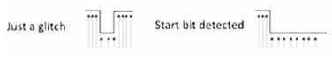
Now we've got two examples. Two pictures up here, it's like timing diagrams. And what they're showing is two different situations. Now remember that this UART, it was made a long time ago. It's made to be robust in the face of noise. So noise, you get all kinds of electromagnetic noise on these signals. So this signal maybe it's supposed to be high because you're not communicating but there's some kind of glitch. Some kind of noise, some kind of electromagnetic noise which forces the signal to go low, mistakenly. Now when that happens, if the receiver is too quick, it might say oh, the signal went low, I guess communication is starting but maybe it's just a glitch, a temporary bounce down. And it shouldn't consider that to be a real signal. It should ignore a short glitch. So what happens is, it's going to measure the time that the signal is low. So on the left, it's just a glitch. The signal goes low but for a very short time. If it's too short then the receiver should say oh, that's not real, that's not really a start. But on the other hand on the right, if this signal goes low and stays low for a significant amount of time then the receiver should say oh, this is a real start I need to synchronize myself. So the receiver has to be able to distinguish between a glitch for a start which is not a real start signal and a real start.
(1) Detection of the start bit is used to synchronize
Synchronization based on falling edge of start bit. So detection of the start bit is used to synchronize the receiver and the transmitter and it's synchronized based on the falling edge of the signal and it recognizes the start bit based on the falling edge.
(2) Start bit is a falling edge
Follow 0 must be long duration to screen out noise.
(3) Receiver samples faster than baud rate (16x typical)
Typically 16 times faster at least, and it's going to count how many times to find the start bit, it's going to count how many samples it's low for. If it's low for enough samples then it says yes, that is a real start.
(4) Start bit is indicated by a 0 of at least half period
The following 0 must be of sufficiently long duration to screen out any kind of noise.
The receiver has to sample faster than the baud rate, typically 16 times faster. That's common. The start bit Is indicated by a 0 for at least half a period. So the length of the period depends on the length of your baud rate. But let's say, you're using a baud rate of 9600 baud. If you remember, the period length of that is 104 microseconds. So the hold period is 104 microseconds, half a period would be 52, 52 microseconds. So the receiver, if it sees that signal go down load for 52 microseconds then it says okay, this is a real start signal. We're really starting communication, I need to synchronize myself now against that falling edge.
2.3 Lecture2-3:UART Parity and Stop
This lecture will continue talking about UART, talk about more of the bits that are transmitted in addition to the data bits and the start bit. So Parity Bit. This is an optional bit that you can transmit with the data. So transmission is assumed to be error prone.
2.3.1 Parity Bit
(1) Transmission medium is assumed to be error-prone
- E-M radiation noise, synchronization accuracy.
So Parity Bit. This is an optional bit that you can transmit with the data. So transmission is assumed to be error prone. This is very common, long distance communication. You can have lots of electromagnetic radiation. Some kind of noise, right? So this maybe synchronization accuracy, or inaccuracy, something like that. There are lots of reasons why there can be noise on a line. So there can be times where you expect a zero. Zero is being transmitted, but the receiver receives a one instead, or vice versa. You transmit a one but the receiver receives a zero, because of various types of noise. So to adjust for that, to take care of that, at least to detect that, we have parity bits. So parity bit is optional.
(2) Parity bit may be transmitted to check for errors
- Even Parity: Number of 1’s is even
- Odd Parity: Number of 1’s is odd
One parity bit can be sent with each packet, each, say group of eight data bits. The parity bit is used to check for error.
So let's say we're sending eight bits, eight data bits. The parity is the count, you either have even parity or odd parity, and it's related to the number of ones that are transmitted. So, if you're transmitting eight bits and an odd number of those bits are ones, then you say you have odd parody. And if an even number of those bits is a one, then you have even parity. So parity's always going to be even or odd. Let's say even is zero and odd's a one. So parities of any sequence of bits is always even or odd depending on how many bits you're transmitting. So what we do is, if we use a parity bit, we send the data bits, and then we also send one more bit which is the parity bit, which is either zero or one. A zero if the parity of the other bits is even, a one if it's odd.
(3) Parity bit is added to ensure even/odd parity
And then what can happen is on the receiving end, it can check the parity. So it can count the number of ones that it received, and checks if it's even or odd, and then it compares that to the parity bit. If the parity bit set is even, it's parity bit is zero, let's say, indicating that it's even parity, and it has an even number of ones, then it assumes, okay, transmission was fine. Where if it gets odd parity, then it assumes that transmission was not fine, and it needs a new transmission. It basically sends some kind of request to say, send me the data again. This parity bit is sent after the data bit. So you have the start bit, then you have the data bits, then you send the parity bit, then you send the stop bit, or bits. You can send one or more stop.
(4) Example Data = 011011010
So here's an example, we've got some series of bits, eight bits, and there are five ones in those eight bits. So it's an odd number of ones, that means this set of eight bits is odd parity. So the parity bit that would be set with this would be a one. So you'd send these eight bits, then you'd send one more one. And the total parity is odd, so now at the receiving end, it, as it counted the number of ones that came in. It counted five ones, it realized that was odd compared to the parity bit, and if the parity is also one, the parity bit's one, then it says this is okay. Where if one of these bits was flipped in transmission, then the parity would have changed, say zero was changed to a one, or one change was zero. Either way, the parity would have become even and it would have noticed a mismatch. So if a single bit is changed, then this can be detected using a parity bit. Note that this is sort of a minimal check because if two bits are altered, then you won't detect it. Because two bits, say you change zero to one then you change a one to a zero, then the total number of ones stays the same even though the data is still incorrect. So you wouldn't catch that. If two bits are changed, you might miss it. You would miss it if two bits are changed, but if a single bit is changed, you could detect that using a parity bit.
2.3.2 Stop Bit
So in addition to the parity bit, you have to have stop bits. Now the parity bit is optional, stop bit is required.
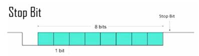
(1) Receiver expects a 1 after all data bits and parity bits
Although you can have one or two stop bits, you have to have at least one stop bit. So in this example, this timing diagram, we show one start bit at the beginning, eight data bits, no parity bit, but then we have the stop bit right at the end. A single stop bit, in this case.
(2) If 1 is not received an error has occurred
Now, the stop bit, basically it's high, it's always high. So after the eight databits are sent and a parody bit, if a parody bit is going to be sent. The signal should be high. So the stop bit is the time when the signal is high after the transmission is done. It's expected to be high. You can take one stop bit or two stop bits. If it's not a high, if it's not a one at that point, then it's assumed that an error has occurred, and retransmition is going to be required.
2.3.3 Data Throughput vs. Baud
(1) Every transmission involves sending signaling bits
So the Baud rate is the maximum number of transitions in a second. The maximum transitions, which is the maximum bits that you can send. And it's true that you can send that many bits, but not all of those bits are actually data bits.
(2) Data throughput rate is lower than baud rate
- Signaling bits must be sent
So the data throughput is not as high as the Baud rate, because you're sending the stop bit, the start bit and the parody bit. Stop bit could be two bits and the parody bit, you send this extra stuff that is not actually data. So the data transmission rate is going to be less than the baud rate.
(3) 8 data bits, 1 parity bit, baud rate =9600
So, these signaling bits have to be sent, so let's imagine an example where you're sending eight data bits. And you're sending one parity bit, and one stop bit, and start bit, let's say. So, you're sending eight data bits, but there are 11 actual bits that you have to send in order to send the eight, right? Because you gotta send the start bit, and the parity bit, and the stop bit, and I'll say the baud rate is 9600 baud. So nice things in a baud would be the maximum rate of the number of bits, 9600 bits per second can be sent. But you're sending 11 bits a second, 8 data bits. So your data throughput, would be less because the transmission efficiency is only eight out of 11. So you get 73% efficiency out of that. So the data throughput rate is actually only 73% of 9600. So you get, 6981 bits per second of data that you can actually send when you're using 9600 baud under those assumptions.


 1836
1836

 被折叠的 条评论
为什么被折叠?
被折叠的 条评论
为什么被折叠?
 到【灌水乐园】发言


