


实时时钟(RTC)是一个独立的BCD定时器/计数器。RTC模块由一个具有可编程报警中断功能的时间日历时钟。
STM32内部RTC功能非常实用,它的供电和时钟是独立于内核的,可以说是STM32内部独立的外设模块,有加上RTC内部寄存器不受系统复位掉电的影响,RTC所需的晶振在RCC部分的寄存器中选择。在芯片时钟系统中对RTC的时钟提供如下图所示。
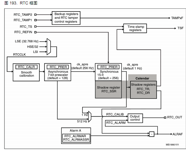
RTC时钟可以从LSI, LSE和HSE分频中选择。这些需要对RCC寄存器的一些位进行设置。对于RTC,包含了两个模块,第一个模块是 RTC的预分频模块,它可编程产生最长为 1秒的 RTC时间基准 TR_CLK。RTC的预分频模块包含了一个 20位的可编程分频器(RTC预分频器)。在每个TR_CLK周期中,如果在 RTC_CR 寄存器中设置了相应允许位,则 RTC产生一个中断(秒中断)。第 2个模块是一个 32位的可编程的计数器,它可被初始化为当前的系统时间。系统时间以 TR_CLK速度增长并与存储在 RTC_ALR寄存器中的可编程的时间相比较,如果 RTC_CR控制寄存器中设置了相应允许位,则比较匹配时将产生一个闹钟中断。在此基础上,我们可以用stm32做一个时钟。现在让我们对其进行设置。
代码:
1.首先,我们要说的是电源管理和备份寄存器时钟,提到备份寄存器这里要说一下,引用手册–“备份寄存器是 10个 16位的寄存器,可用来存储 20个字节的用户应用程序数据。他们处在备份域里,当 VDD电源被切断,他们仍然由 VBAT维持供电。当系统在待机模式下被唤醒,或系统复位或电源复位时,他们也不会被复位。侵入检测事件发生时(即 TAMPxF=1)或闪存读出保护被禁用时,该寄存器复位。
2.使能RTC和备份寄存器的访问(复位默认关闭)。引用手册–“复位后,对备份寄存器和 RTC的访问被禁止,并且备份域被保护以防止可能存在的意外的写操作。电源控制寄存器(PWR_CR)的 DBP位必须被置 1,以允许访问备份寄存器和RTC.”因为程序要对RTC和备份寄存器操作,所以必须使能。
3.选择外部低速晶体为RTC时钟,并使能时钟;
4.使能秒中断,程序里在秒中断里置位标志位来通知主程序显示时间数据,同时在32位计数器到23:59:59时清零;
5.设置RTC预分频器值产生1秒信号计算公式 fTR_CLK = fRTCCLK/(PRL+1),我们设置32767来产生秒信号;
void Configure_RTC(void)
{
    RTC_InitTypeDef RTC_InitStructure;

    RCC_APB1PeriphClockCmd(RCC_APB1Periph_PWR , ENABLE);
    PWR_BackupAccessCmd(ENABLE);
    //RCC_LSICmd(ENABLE);
    RCC_LSEConfig(RCC_LSE_ON);
    while (RCC_GetFlagStatus(RCC_FLAG_LSERDY) == RESET)
  {
  }

    RCC_RTCCLKConfig(RCC_RTCCLKSource_LSE);

    SynchPrediv = 0xFF;
    AsynchPrediv = 0x7F;
    RCC_RTCCLKCmd(ENABLE);
    RTC_WaitForSynchro();
}
由于用户是通过APB1接口读写RTC寄存器,在上电之后,需要先等待APB1接口与RTC同步完成,否则读取的RTC值可能有误;笔者就在写程序时将打开HSI和配置APB同步的顺序弄错了,造成时间不准,请教学长才得以解决,希望大家也要注意。(:完成同步以RTC_CRL的RSF位置1为标志。对于写RTC寄存器,先查询RTC_CRL的RTOFF位,直到为1,说明上一次操作已经完成;再CNF置1,进入配置模式;写寄存器;CNF置0,退出配置模式;等待RTOFF位为1,说明本次写入已经完成。
为了方便时间校准,我们可以在开始的时候进行一次时间设置。(使用的官方的代码,大家可以在库例程中找到)
void RTC_TimeRegulate(void)
{
  RTC_TimeTypeDef RTC_TimeStructure;
  RTC_AlarmTypeDef  RTC_AlarmStructure;
  uint32_t tmp_hh = 0xFF, tmp_mm = 0xFF, tmp_ss = 0xFF;

  printf("\n\r==============Time Settings=====================================\n\r");
  RTC_TimeStructure.RTC_H12     = RTC_H12_AM;
  printf("  Please Set Hours:\n\r");
  while (tmp_hh == 0xFF)
  {
    tmp_hh = USART_Scanf(23);
    RTC_TimeStructure.RTC_Hours = tmp_hh;
  }
  printf("  %0.2d\n\r", tmp_hh);

  printf("  Please Set Minutes:\n\r");
  while (tmp_mm == 0xFF)
  {
    tmp_mm = USART_Scanf(59);
    RTC_TimeStructure.RTC_Minutes = tmp_mm;
  }
  printf("  %0.2d\n\r", tmp_mm);

  printf("  Please Set Seconds:\n\r");
  while (tmp_ss == 0xFF)
  {
    tmp_ss = USART_Scanf(59);
    RTC_TimeStructure.RTC_Seconds = tmp_ss;
  }
    RTC_SetTime(RTC_Format_BCD, &RTC_TimeStructure);
  printf("  %0.2d\n\r", tmp_ss);

  /* Configure the RTC time register */
  if(RTC_SetTime(RTC_Format_BIN, &RTC_TimeStructure) == ERROR)
  {
    printf("\n\r>> !! RTC Set Time failed. !! <<\n\r");
  }
  else
  {
    printf("\n\r>> !! RTC Set Time success. !! <<\n\r");
    RTC_TimeShow();
    /* Indicator for the RTC configuration */
    RTC_WriteBackupRegister(RTC_BKP_DR0, 0x32F0 );
  }

  tmp_hh = 0xFF;
  tmp_mm = 0xFF;
  tmp_ss = 0xFF;

  /* Disable the Alarm A */
  RTC_AlarmCmd(RTC_Alarm_A, DISABLE);

  printf("\n\r==============Alarm A Settings=====================================\n\r");
  RTC_AlarmStructure.RTC_AlarmTime.RTC_H12 = RTC_H12_AM;
  printf("  Please Set Alarm Hours:\n\r");
  while (tmp_hh == 0xFF)
  {
    tmp_hh = USART_Scanf(23);
    RTC_AlarmStructure.RTC_AlarmTime.RTC_Hours = tmp_hh;
  }
  printf("  %0.2d\n\r", tmp_hh);

  printf("  Please Set Alarm Minutes:\n\r");
  while (tmp_mm == 0xFF)
  {
    tmp_mm = USART_Scanf(59);
    RTC_AlarmStructure.RTC_AlarmTime.RTC_Minutes = tmp_mm;
  }
  printf("  %0.2d\n\r", tmp_mm);

  printf("  Please Set Alarm Seconds:\n\r");
  while (tmp_ss == 0xFF)
  {
    tmp_ss = USART_Scanf(59);
    RTC_AlarmStructure.RTC_AlarmTime.RTC_Seconds = tmp_ss;
  }
  printf("  %0.2d", tmp_ss);

  /* Set the Alarm A */
  RTC_AlarmStructure.RTC_AlarmDateWeekDaySel = RTC_AlarmDateWeekDaySel_Date;
  RTC_AlarmStructure.RTC_AlarmDateWeekDay = RTC_Weekday_Monday;
  RTC_AlarmStructure.RTC_AlarmMask = RTC_AlarmMask_DateWeekDay;
    RTC_SetAlarm(RTC_Format_BCD, RTC_Alarm_A, &RTC_AlarmStructure);

  /* Configure the RTC Alarm A register */
  RTC_SetAlarm(RTC_Format_BIN, RTC_Alarm_A, &RTC_AlarmStructure);
  printf("\n\r>> !! RTC Set Alarm success. !! <<\n\r");
  RTC_AlarmShow();

  /* Enable the RTC Alarm A Interrupt */
  RTC_ITConfig(RTC_IT_ALRA, ENABLE);

  /* Enable the alarm  A */
  RTC_AlarmCmd(RTC_Alarm_A, ENABLE);
}

void RTC_TimeShow(void)
{
  RTC_TimeTypeDef RTC_TimeStructure;
  /* Get the current Time */
  RTC_GetTime(RTC_Format_BIN, &RTC_TimeStructure);
  printf("\n\r  The current time is :  %0.2d:%0.2d:%0.2d \n\r", \
    RTC_TimeStructure.RTC_Hours, RTC_TimeStructure.RTC_Minutes, RTC_TimeStructure.RTC_Seconds);
}

/**
  * @brief  Display the current time on the Hyperterminal.
  * @param  None
  * @retval None
  */
void RTC_AlarmShow(void)
{
  RTC_AlarmTypeDef  RTC_AlarmStructure;
  /* Get the current Alarm */
  RTC_GetAlarm(RTC_Format_BIN, RTC_Alarm_A, &RTC_AlarmStructure);
  printf("\n\r  The current alarm is :  %0.2d:%0.2d:%0.2d \n\r",\
    RTC_AlarmStructure.RTC_AlarmTime.RTC_Hours, RTC_AlarmStructure.RTC_AlarmTime.RTC_Minutes, RTC_AlarmStructure.RTC_AlarmTime.RTC_Seconds);
}

uint8_t USART_Scanf(uint32_t value)
{
  uint32_t index = 0;
  uint32_t tmp[2] = {0, 0};

  while (index < 2)
  {
    /* Loop until RXNE = 1 */
    while (USART_GetFlagStatus(USART2, USART_FLAG_RXNE) == RESET)
    {}
    tmp[index++] = (USART_ReceiveData(USART2));
    if ((tmp[index - 1] < 0x30) || (tmp[index - 1] > 0x39))
    {
      printf("\n\r Please enter valid number between 0 and 9 \n\r");
      index--;
    }
  }
  /* Calculate the Corresponding value */
  index = (tmp[1] - 0x30) + ((tmp[0] - 0x30) * 10);
  /* Checks */
  if (index > value)
  {
    printf("\n\r Please enter valid number between 0 and %d \n\r", value);
    return 0xFF;
  }
  return index;
}设置闹钟和时钟,使用串口输入,使用按键产生中断查看当前时间并使用串口查看。关于串口和按键的内容,按键点我,串口点我 就不一一赘述了,大家可以看以前的文章。
最后,我们开始写主函数完成功能:
int main(void)
{
    RTC_InitTypeDef RTC_InitStructure;
    LED_Init();
  Uart_Init();
    Nvic_Init();
    EXTI_KEY_Init();
    if (RTC_ReadBackupRegister(RTC_BKP_DR0) != 0x32F0)
  {
    /* RTC configuration  */
    Configure_RTC();
      RTC_InitStructure.RTC_AsynchPrediv = AsynchPrediv;
    RTC_InitStructure.RTC_SynchPrediv = SynchPrediv;
        RTC_InitStructure.RTC_HourFormat = RTC_HourFormat_24;
    /* Check on RTC init */
    if (RTC_Init(&RTC_InitStructure) == ERROR)
    {
      printf("\n\r        /!\\***** RTC Prescaler Config failed ********/!\\ \n\r");
    }
    RTC_TimeRegulate();
  }
  else
  {
    /* Check if the Power On Reset flag is set */
    if (RCC_GetFlagStatus(RCC_FLAG_PORRST) != RESET)
    {
      printf("\r\n Power On Reset occurred....\n\r");
    }
    /* Check if the Pin Reset flag is set */
    else if (RCC_GetFlagStatus(RCC_FLAG_PINRST) != RESET)
    {
      printf("\r\n External Reset occurred....\n\r");
    }

    printf("\n\r No need to configure RTC....\n\r");

    /* Enable the PWR clock */
    RCC_APB1PeriphClockCmd(RCC_APB1Periph_PWR, ENABLE);

    /* Allow access to RTC */
    PWR_BackupAccessCmd(ENABLE);
    /* Wait for RTC APB registers synchronisation */
    RTC_WaitForSynchro();

    /* Clear the RTC Alarm Flag */
    RTC_ClearFlag(RTC_FLAG_ALRAF);

    /* Clear the EXTI Line 17 Pending bit (Connected internally to RTC Alarm) */
    EXTI_ClearITPendingBit(EXTI_Line17);

    /* Display the RTC Time and Alarm */
    RTC_TimeShow();
    RTC_AlarmShow();
  }
     while (1)
  {
        if(flag==1)
        {
            flag = 0;
            RTC_TimeShow();
        }
        if(flag1==1)
        {
            flag1=0;
            GPIO_SetBits(GPIOA ,GPIO_Pin_5);
            printf("\r\nAlarm\n\r");
        }
    }
}
在此程序中没有使用日期功能,使用日期的方式与时间差不多,闹钟功能实现了到点亮灯(当然你也可以加个蜂鸣器,我就不多说了)。


 336
336

 被折叠的 条评论
为什么被折叠?
被折叠的 条评论
为什么被折叠?
 到【灌水乐园】发言


