


1、背景介绍
ZYNQ在PL部分使用AXI_QUAD_SPI IP核外挂了8片SPI FLASH,VIVADO示例图如下:
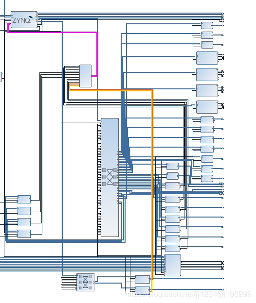

上图中有颜色的线条为IP核的中断到ZYNQ PL-PS中断,由于设备太多,这里使用了中断级联。IP核的地址分配如下:

2、内核配置
内核中需要修改下面文件

增加兼容的硬件spi型号,这里使用的n25q256

完整代码如下:
/*
 * MTD SPI driver for ST M25Pxx (and similar) serial flash chips
 *
 * Author: Mike Lavender, mike@steroidmicros.com
 *
 * Copyright (c) 2005, Intec Automation Inc.
 *
 * Some parts are based on lart.c by Abraham Van Der Merwe
 *
 * Cleaned up and generalized based on mtd_dataflash.c
 *
 * This code is free software; you can redistribute it and/or modify
 * it under the terms of the GNU General Public License version 2 as
 * published by the Free Software Foundation.
 *
 */

#include <linux/err.h>
#include <linux/errno.h>
#include <linux/module.h>
#include <linux/device.h>

#include <linux/mtd/mtd.h>
#include <linux/mtd/partitions.h>

#include <linux/spi/spi.h>
#include <linux/spi/flash.h>
#include <linux/mtd/spi-nor.h>
#include <linux/of.h>

static ssize_t m25p80_write(struct spi_nor *nor, loff_t to, size_t len,
			    const u_char *buf);
static ssize_t m25p80_read(struct spi_nor *nor, loff_t from, size_t len,
			   u_char *buf);


#define	MAX_CMD_SIZE		6
struct m25p {
	struct spi_device	*spi;
	struct spi_nor		spi_nor;
	u8			command[MAX_CMD_SIZE];
};

static int m25p80_read_reg(struct spi_nor *nor, u8 code, u8 *val, int len)
{
//printk("##################m25p80 read reg\n");
	struct m25p *flash = nor->priv;
	struct spi_device *spi = flash->spi;
	int ret;

//printk("code is 0x%x,len:%d,---%x----\n",code,len,*val);
	ret = spi_write_then_read(spi, &code, 1, val, len);
	if (ret < 0)
		dev_err(&spi->dev, "error %d reading %x\n", ret, code);

	return ret;
}

static void m25p_addr2cmd(struct spi_nor *nor, unsigned int addr, u8 *cmd)
{
	/* opcode is in cmd[0] */
	cmd[1] = addr >> (nor->addr_width * 8 -  8);
	cmd[2] = addr >> (nor->addr_width * 8 - 16);
	cmd[3] = addr >> (nor->addr_width * 8 - 24);
	cmd[4] = addr >> (nor->addr_width * 8 - 32);
}

static int m25p_cmdsz(struct spi_nor *nor)
{
	return 1 + nor->addr_width;
}

static int m25p80_write_reg(struct spi_nor *nor, u8 opcode, u8 *buf, int len)
{
	struct m25p *flash = nor->priv;
	struct spi_device *spi = flash->spi;

	flash->command[0] = opcode;
	if (buf)
		memcpy(&flash->command[1], buf, len);

	return spi_write(spi, flash->command, len + 1);
}

static ssize_t m25p80_write(struct spi_nor *nor, loff_t to, size_t len,
			    const u_char *buf)
{
	struct m25p *flash = nor->priv;
	struct spi_device *spi = flash->spi;
	struct spi_transfer t[2] = {};
	struct spi_message m;
	int cmd_sz = m25p_cmdsz(nor);
	ssize_t ret;
//printk("m25p80_write write len :%d,%x\n",len,*buf);
	spi_message_init(&m);

	if (nor->program_opcode == SPINOR_OP_AAI_WP && nor->sst_write_second)
		cmd_sz = 1;

	flash->command[0] = nor->program_opcode;
	m25p_addr2cmd(nor, to, flash->command);

	t[0].tx_buf = flash->command;
	t[0].len = cmd_sz;
	spi_message_add_tail(&t[0], &m);

	t[1].tx_buf = buf;
	t[1].len = len;
	spi_message_add_tail(&t[1], &m);

	ret = spi_sync(spi, &m);
	if (ret)
		return ret;

	ret = m.actual_length - cmd_sz;
	if (ret < 0)
		return -EIO;
	return ret;
}

static inline unsigned int m25p80_rx_nbits(struct spi_nor *nor)
{
	switch (nor->flash_read) {
	case SPI_NOR_DUAL:
		return 2;
	case SPI_NOR_QUAD:
		return 4;
	default:
		return 0;
	}
}

/*
 * Read an address range from the nor chip.  The address range
 * may be any size provided it is within the physical boundaries.
 */
static ssize_t m25p80_read(struct spi_nor *nor, loff_t from, size_t len,
			   u_char *buf)
{
	struct m25p *flash = nor->priv;
	struct spi_device *spi = flash->spi;
	struct spi_transfer t[2];
	struct spi_message m;
	unsigned int dummy = nor->read_dummy;
	ssize_t ret;
//printk("m25p80_read read len :%d,%x\n",len,*buf);

	/* convert the dummy cycles to the number of bytes */
	dummy /= 8;

	if (spi_flash_read_supported(spi)) {
		struct spi_flash_read_message msg;

		memset(&msg, 0, sizeof(msg));

		msg.buf = buf;
		msg.from = from;
		msg.len = len;
		msg.read_opcode = nor->read_opcode;
		msg.addr_width = nor->addr_width;
		msg.dummy_bytes = dummy;
		/* TODO: Support other combinations */
		msg.opcode_nbits = SPI_NBITS_SINGLE;
		msg.addr_nbits = SPI_NBITS_SINGLE;
		msg.data_nbits = m25p80_rx_nbits(nor);

		ret = spi_flash_read(spi, &msg);
		if (ret < 0)
			return ret;
		return msg.retlen;
	}

	spi_message_init(&m);
	memset(t, 0, (sizeof t));

	flash->command[0] = nor->read_opcode;
	m25p_addr2cmd(nor, from, flash->command);

	t[0].tx_buf = flash->command;
	t[0].len = m25p_cmdsz(nor) + dummy;
	t[0].dummy = nor->read_dummy;
	spi_message_add_tail(&t[0], &m);

	t[1].rx_buf = buf;
	t[1].rx_nbits = m25p80_rx_nbits(nor);
	t[1].len = min(len, spi_max_transfer_size(spi));
	spi_message_add_tail(&t[1], &m);

	ret = spi_sync(spi, &m);
	if (ret)
		return ret;

	ret = m.actual_length - m25p_cmdsz(nor) - dummy;
	if (ret < 0)
		return -EIO;
	return ret;
}

/*
 * board specific setup should have ensured the SPI clock used here
 * matches what the READ command supports, at least until this driver
 * understands FAST_READ (for clocks over 25 MHz).
 */
static int m25p_probe(struct spi_device *spi)
{
	struct flash_platform_data	*data;
	struct m25p *flash;
	struct spi_nor *nor;
	struct mtd_info *mtd = NULL;
	enum read_mode mode = SPI_NOR_NORMAL;
	char *flash_name;
	int ret;
	unsigned int chip_num = 0;
//	printk("enter probe ...\n");
	data = dev_get_platdata(&spi->dev);

	flash = devm_kzalloc(&spi->dev, sizeof(*flash), GFP_KERNEL);
	if (!flash)
		return -ENOMEM;

	nor = &flash->spi_nor;
	mtd = &nor->mtd;
	/* install the hooks */
	nor->read = m25p80_read;
	nor->write = m25p80_write;
	nor->write_reg = m25p80_write_reg;
	nor->read_reg = m25p80_read_reg;

	nor->dev = &spi->dev;
	spi_nor_set_flash_node(nor, spi->dev.of_node);
	nor->priv = flash;

	spi_set_drvdata(spi, flash);
	flash->spi = spi;
	nor->spi = spi;

	if (spi->mode & SPI_RX_QUAD)
		mode = SPI_NOR_QUAD;
	else if (spi->mode & SPI_RX_DUAL)
		mode = SPI_NOR_DUAL;

	if (data && data->name)
		nor->mtd.name = data->name;

	/* For some (historical?) reason many platforms provide two different
	 * names in flash_platform_data: "name" and "type". Quite often name is
	 * set to "m25p80" and then "type" provides a real chip name.
	 * If that's the case, respect "type" and ignore a "name".
	 */
	if (data && data->type)
		flash_name = data->type;
	else if (!strcmp(spi->modalias, "spi-nor"))
		flash_name = NULL; /* auto-detect */
	else
		flash_name = spi->modalias;

//printk("flash name is %s\n",flash_name);

	ret = spi_nor_scan(nor, flash_name, mode);

	if (ret)
		return ret;
        of_property_read_u32(spi->dev.of_node, "chip_num",
				&chip_num);
	if(chip_num>0)
	{
	    nor->mtd.size = nor->mtd.size*chip_num;
	}
//printk("mtd .name = %s, .size = 0x%llx (%lldMiB), "
//		".erasesize = 0x%.8x (%uKiB) .numeraseregions = %d\n",
//		nor->mtd.name, (long long)nor->mtd.size, (long long)(nor->mtd.size >> 20),
//		nor->mtd.erasesize, nor->mtd.erasesize / 1024, nor->mtd.numeraseregions);
	return mtd_device_register(&nor->mtd, data ? data->parts : NULL,
				   data ? data->nr_parts : 0);
}


static int m25p_remove(struct spi_device *spi)
{
	struct m25p	*flash = spi_get_drvdata(spi);

	/* Clean up MTD stuff. */
	return mtd_device_unregister(&flash->spi_nor.mtd);
}

/*
 * Do NOT add to this array without reading the following:
 *
 * Historically, many flash devices are bound to this driver by their name. But
 * since most of these flash are compatible to some extent, and their
 * differences can often be differentiated by the JEDEC read-ID command, we
 * encourage new users to add support to the spi-nor library, and simply bind
 * against a generic string here (e.g., "jedec,spi-nor").
 *
 * Many flash names are kept here in this list (as well as in spi-nor.c) to
 * keep them available as module aliases for existing platforms.
 */
static const struct spi_device_id m25p_ids[] = {
	/*
	 * Allow non-DT platform devices to bind to the "spi-nor" modalias, and
	 * hack around the fact that the SPI core does not provide uevent
	 * matching for .of_match_table
	 */
	{"spi-nor"},

	/*
	 * Entries not used in DTs that should be safe to drop after replacing
	 * them with "spi-nor" in platform data.
	 */
	{"s25sl064a"},	{"w25x16"},	{"m25p10"},	{"m25px64"},

	/*
	 * Entries that were used in DTs without "jedec,spi-nor" fallback and
	 * should be kept for backward compatibility.
	 */
	{"at25df321a"},	{"at25df641"},	{"at26df081a"},
	{"mr25h256"},
	{"mx25l4005a"},	{"mx25l1606e"},	{"mx25l6405d"},	{"mx25l12805d"},
	{"mx25l25635e"},{"mx66l51235l"},
	{"n25q064"},	{"n25q128a11"},	{"n25q128a13"},	{"n25q512a"},{"n25q256a"},
	{"s25fl256s1"},	{"s25fl512s"},	{"s25sl12801"},	{"s25fl008k"},
	{"s25fl064k"},
	{"sst25vf040b"},{"sst25vf016b"},{"sst25vf032b"},{"sst25wf040"},
	{"m25p40"},	{"m25p80"},	{"m25p16"},	{"m25p32"},
	{"m25p64"},	{"m25p128"},
	{"w25x80"},	{"w25x32"},	{"w25q32"},	{"w25q32dw"},
	{"w25q80bl"},	{"w25q128"},	{"w25q256"},

	/* Flashes that can't be detected using JEDEC */
	{"m25p05-nonjedec"},	{"m25p10-nonjedec"},	{"m25p20-nonjedec"},
	{"m25p40-nonjedec"},	{"m25p80-nonjedec"},	{"m25p16-nonjedec"},
	{"m25p32-nonjedec"},	{"m25p64-nonjedec"},	{"m25p128-nonjedec"},

	{ },
};
MODULE_DEVICE_TABLE(spi, m25p_ids);

static const struct of_device_id m25p_of_table[] = {
	/*
	 * Generic compatibility for SPI NOR that can be identified by the
	 * JEDEC READ ID opcode (0x9F). Use this, if possible.
	 */
	{ .compatible = "jedec,spi-nor" },
	{ .compatible = "n25q256,spi-nor" },

	{}
};
MODULE_DEVICE_TABLE(of, m25p_of_table);

static struct spi_driver m25p80_driver = {
	.driver = {
		.name	= "n25q256a",
		.of_match_table = m25p_of_table,
	},
	.id_table	= m25p_ids,
	.probe	= m25p_probe,
	.remove	= m25p_remove,

	/* REVISIT: many of these chips have deep power-down modes, which
	 * should clearly be entered on suspend() to minimize power use.
	 * And also when they're otherwise idle...
	 */
};

module_spi_driver(m25p80_driver);

MODULE_LICENSE("GPL");
MODULE_AUTHOR("Mike Lavender");
MODULE_DESCRIPTION("MTD SPI driver for ST M25Pxx flash chips");
3、devicetree配置
设备树可以用sdk产生,但是生成完后要修改ip核的节点说明,如下:

其中增加了中断描述信息,另外外挂的flash型号也需要描述。
完整的设备树信息如下:
/dts-v1/;

/ {
	#address-cells = <0x1>;
	#size-cells = <0x1>;
	compatible = "xlnx,zynq-7000";

	cpus {
		#address-cells = <0x1>;
		#size-cells = <0x0>;

		cpu@0 {
			compatible = "arm,cortex-a9";
			device_type = "cpu";
			reg = <0x0>;
			clocks = <0x1 0x3>;
			clock-latency = <0x3e8>;
			cpu0-supply = <0x2>;
			operating-points = <0xa4cb8 0xf4240 0x5265c 0xf4240>;
		};

		cpu@1 {
			compatible = "arm,cortex-a9";
			device_type = "cpu";
			reg = <0x1>;
			clocks = <0x1 0x3>;
		};
	};

	fpga-full {
		compatible = "fpga-region";
		fpga-mgr = <0x3>;
		#address-cells = <0x1>;
		#size-cells = <0x1>;
		ranges;
	};

	pmu@f8891000 {
		compatible = "arm,cortex-a9-pmu";
		interrupts = <0x0 0x5 0x4 0x0 0x6 0x4>;
		interrupt-parent = <0x4>;
		reg = <0xf8891000 0x1000 0xf8893000 0x1000>;
	};

	fixedregulator {
		compatible = "regulator-fixed";
		regulator-name = "VCCPINT";
		regulator-min-microvolt = <0xf4240>;
		regulator-max-microvolt = <0xf4240>;
		regulator-boot-on;
		regulator-always-on;
		linux,phandle = <0x2>;
		phandle = <0x2>;
	};

	amba {
		u-boot,dm-pre-reloc;
		compatible = "simple-bus";
		#address-cells = <0x1>;
		#size-cells = <0x1>;
		interrupt-parent = <0x4>;
		ranges;

		adc@f8007100 {
			compatible = "xlnx,zynq-xadc-1.00.a";
			reg = <0xf8007100 0x20>;
			interrupts = <0x0 0x7 0x4>;
			interrupt-parent = <0x4>;
			clocks = <0x1 0xc>;

			xlnx,channels {
				#address-cells = <0x1>;
				#size-cells = <0x0>;

				channel@0 {
					reg = <0x0>;
				};

				channel@1 {
					reg = <0x1>;
				};

				channel@2 {
					reg = <0x2>;
				};

				channel@3 {
					reg = <0x3>;
				};

				channel@4 {
					reg = <0x4>;
				};

				channel@5 {
					reg = <0x5>;
				};

				channel@6 {
					reg = <0x6>;
				};

				channel@7 {
					reg = <0x7>;
				};

				channel@8 {
					reg = <0x8>;
				};

				channel@9 {
					reg = <0x9>;
				};

				channel@a {
					reg = <0xa>;
				};

				channel@b {
					reg = <0xb>;
				};

				channel@c {
					reg = <0xc>;
				};

				channel@d {
					reg = <0xd>;
				};

				channel@e {
					reg = <0xe>;
				};

				channel@f {
					reg = <0xf>;
				};

				channel@10 {
					reg = <0x10>;
				};
			};
		};

		gpio@e000a000 {
			compatible = "xlnx,zynq-gpio-1.0";
			#gpio-cells = <0x2>;
			clocks = <0x1 0x2a>;
			gpio-controller;
			interrupt-controller;
			#interrupt-cells = <0x2>;
			interrupt-parent = <0x4>;
			interrupts = <0x0 0x14 0x4>;
			reg = <0xe000a000 0x1000>;
		};

		i2c@e0004000 {
			compatible = "cdns,i2c-r1p10-slave";
			status = "okay";
			clocks = <0x1 0x26>;
			interrupt-parent = <0x4>;
			interrupts = <0x0 0x19 0x4>;
			reg = <0xe0004000 0x1000>;
			#address-cells = <0x1>;
			#size-cells = <0x0>;
			clock-frequency = <0x61a80>;
		};

		i2c@e0005000 {
			compatible = "cdns,i2c-r1p10-slave";
			status = "okay";
			clocks = <0x1 0x27>;
			interrupt-parent = <0x4>;
			interrupts = <0x0 0x30 0x4>;
			reg = <0xe0005000 0x1000>;
			#address-cells = <0x1>;
			#size-cells = <0x0>;
			clock-frequency = <0x61a80>;
		};

		interrupt-controller@f8f01000 {
			compatible = "arm,cortex-a9-gic";
			#interrupt-cells = <0x3>;
			interrupt-controller;
			reg = <0xf8f01000 0x1000 0xf8f00100 0x100>;
			num_cpus = <0x2>;
			num_interrupts = <0x60>;
			linux,phandle = <0x4>;
			phandle = <0x4>;
		};

		cache-controller@f8f02000 {
			compatible = "arm,pl310-cache";
			reg = <0xf8f02000 0x1000>;
			interrupts = <0x0 0x2 0x4>;
			arm,data-latency = <0x3 0x2 0x2>;
			arm,tag-latency = <0x2 0x2 0x2>;
			cache-unified;
			cache-level = <0x2>;
		};

		memory-controller@f8006000 {
			compatible = "xlnx,zynq-ddrc-a05";
			reg = <0xf8006000 0x1000>;
		};

		ocmc@f800c000 {
			compatible = "xlnx,zynq-ocmc-1.0";
			interrupt-parent = <0x4>;
			interrupts = <0x0 0x3 0x4>;
			reg = <0xf800c000 0x1000>;
		};

		serial@e0000000 {
			compatible = "xlnx,xuartps", "cdns,uart-r1p8";
			status = "okay";
			clocks = <0x1 0x17 0x1 0x28>;
			clock-names = "uart_clk", "pclk";
			reg = <0xe0000000 0x1000>;
			interrupts = <0x0 0x1b 0x4>;
			device_type = "serial";
			port-number = <0x4>;
		};

		spi@e000d000 {
			clock-names = "ref_clk", "pclk";
			clocks = <0x1 0xa 0x1 0x2b>;
			compatible = "xlnx,zynq-qspi-1.0";
			status = "okay";
			interrupt-parent = <0x4>;
			interrupts = <0x0 0x13 0x4>;
			reg = <0xe000d000 0x1000>;
			#address-cells = <0x1>;
			#size-cells = <0x0>;
			is-dual = <0x1>;
			num-cs = <0x1>;
		};

		ethernet@e000b000 {
			compatible = "xlnx,ps7-ethernet-1.00.a";
			reg = <0xe000b000 0x1000>;
			status = "okay";
			interrupts = <0x0 0x16 0x4>;
			clocks = <0x1 0xd 0x1 0x1e>;
			clock-names = "ref_clk", "aper_clk";
			#address-cells = <0x1>;
			#size-cells = <0x0>;
			enet-reset = <0x4 0x2f 0x0>;
			#local-mac-address = [00 0b 35 11 12 00];
			local-mac-address = [00 0b 44 00 3e 16];
			phy-mode = "rgmii";
			phy-handle = <0x7>;
			xlnx,eth-mode = <0x1>;
			xlnx,has-mdio = <0x1>;
			xlnx,ptp-enet-clock = <0x69f6bcb>;

			mdio {
				#address-cells = <0x1>;
				#size-cells = <0x0>;

				phy@2 {
					compatible = "marvell,88e1111";
					device_type = "ethernet-phy";
					reg = <0x2>;
					linux,phandle = <0x7>;
					phandle = <0x7>;
				};
			};
		};

		ethernet@e000c000 {
			compatible = "xlnx,ps7-ethernet-1.00.b";
			reg = <0xe000c000 0x1000>;
			status = "okay";
			interrupts = <0x0 0x2d 0x4>;
			clocks = <0x1 0xe 0x1 0x1f>;
			clock-names = "ref_clk", "aper_clk";
			#address-cells = <0x1>;
			#size-cells = <0x0>;
			enet-reset = <0x4 0x2f 0x0>;
			local-mac-address = [00 0b 36 11 11 00];
			phy-mode = "rgmii";
			phy-handle = <0x8>;
			xlnx,eth-mode = <0x1>;
			xlnx,has-mdio = <0x1>;
			xlnx,ptp-enet-clock = <0x69f6bcb>;

			mdio {
				#address-cells = <0x1>;
				#size-cells = <0x0>;

				phy@1 {
					compatible = "marvell,88e1111";
					device_type = "ethernet-phy";
					reg = <0x1>;
					linux,phandle = <0x8>;
					phandle = <0x8>;
				};
			};
		};

		slcr@f8000000 {
			#address-cells = <0x1>;
			#size-cells = <0x1>;
			compatible = "xlnx,zynq-slcr", "syscon", "simple-mfd";
			reg = <0xf8000000 0x1000>;
			ranges;
			linux,phandle = <0x5>;
			phandle = <0x5>;

			clkc@100 {
				#clock-cells = <0x1>;
				compatible = "xlnx,ps7-clkc";
				fclk-enable = <0x3>;
				clock-output-names = "armpll", "ddrpll", "iopll", "cpu_6or4x", "cpu_3or2x", "cpu_2x", "cpu_1x", "ddr2x", "ddr3x", "dci", "lqspi", "smc", "pcap", "gem0", "gem1", "fclk0", "fclk1", "fclk2", "fclk3", "can0", "can1", "sdio0", "sdio1", "uart0", "uart1", "spi0", "spi1", "dma", "usb0_aper", "usb1_aper", "gem0_aper", "gem1_aper", "sdio0_aper", "sdio1_aper", "spi0_aper", "spi1_aper", "can0_aper", "can1_aper", "i2c0_aper", "i2c1_aper", "uart0_aper", "uart1_aper", "gpio_aper", "lqspi_aper", "smc_aper", "swdt", "dbg_trc", "dbg_apb";
				reg = <0x100 0x100>;
				ps-clk-frequency = <0x2faf080>;
				linux,phandle = <0x1>;
				phandle = <0x1>;
			};

			rstc@200 {
				compatible = "xlnx,zynq-reset";
				reg = <0x200 0x48>;
				#reset-cells = <0x1>;
				syscon = <0x5>;
			};

			pinctrl@700 {
				compatible = "xlnx,pinctrl-zynq";
				reg = <0x700 0x200>;
				syscon = <0x5>;
			};
		};

		dmac@f8003000 {
			compatible = "arm,pl330", "arm,primecell";
			reg = <0xf8003000 0x1000>;
			interrupt-parent = <0x4>;
			interrupt-names = "abort", "dma0", "dma1", "dma2", "dma3", "dma4", "dma5", "dma6", "dma7";
			interrupts = <0x0 0xd 0x4 0x0 0xe 0x4 0x0 0xf 0x4 0x0 0x10 0x4 0x0 0x11 0x4 0x0 0x28 0x4 0x0 0x29 0x4 0x0 0x2a 0x4 0x0 0x2b 0x4>;
			#dma-cells = <0x1>;
			#dma-channels = <0x8>;
			#dma-requests = <0x4>;
			clocks = <0x1 0x1b>;
			clock-names = "apb_pclk";
		};

		devcfg@f8007000 {
			compatible = "xlnx,zynq-devcfg-1.0";
			interrupt-parent = <0x4>;
			interrupts = <0x0 0x8 0x4>;
			reg = <0xf8007000 0x100>;
			clocks = <0x1 0xc 0x1 0xf 0x1 0x10 0x1 0x11 0x1 0x12>;
			clock-names = "ref_clk", "fclk0", "fclk1", "fclk2", "fclk3";
			syscon = <0x5>;
			linux,phandle = <0x3>;
			phandle = <0x3>;
		};

		efuse@f800d000 {
			compatible = "xlnx,zynq-efuse";
			reg = <0xf800d000 0x20>;
		};

		timer@f8f00200 {
			compatible = "arm,cortex-a9-global-timer";
			reg = <0xf8f00200 0x20>;
			interrupts = <0x1 0xb 0x301>;
			interrupt-parent = <0x4>;
			clocks = <0x1 0x4>;
		};

		timer@f8001000 {
			interrupt-parent = <0x4>;
			interrupts = <0x0 0xa 0x4 0x0 0xb 0x4 0x0 0xc 0x4>;
			compatible = "cdns,ttc";
			clocks = <0x1 0x6>;
			reg = <0xf8001000 0x1000>;
		};

		timer@f8002000 {
			interrupt-parent = <0x4>;
			interrupts = <0x0 0x25 0x4 0x0 0x26 0x4 0x0 0x27 0x4>;
			compatible = "cdns,ttc";
			clocks = <0x1 0x6>;
			reg = <0xf8002000 0x1000>;
		};

		timer@f8f00600 {
			interrupt-parent = <0x4>;
			interrupts = <0x1 0xd 0x301>;
			compatible = "arm,cortex-a9-twd-timer";
			reg = <0xf8f00600 0x20>;
			clocks = <0x1 0x4>;
		};

		watchdog@f8005000 {
			clocks = <0x1 0x2d>;
			compatible = "cdns,wdt-r1p2";
			interrupt-parent = <0x4>;
			interrupts = <0x0 0x9 0x1>;
			reg = <0xf8005000 0x1000>;
			timeout-sec = <0xa>;
		};
	};

	amba_pl {
		#address-cells = <0x1>;
		#size-cells = <0x1>;
		compatible = "simple-bus";
		ranges;

		i2c@41600000 {
			#address-cells = <0x1>;
			#size-cells = <0x0>;
			clock-names = "ref_clk";
			clocks = <0x1 0xf>;
			compatible = "xlnx,xps-iic-2.00.a";
			interrupt-names = "iic2intc_irpt";
			interrupt-parent = <0x4>;
			interrupts = <0x0 0x1f 0x4>;
			reg = <0x41600000 0x10000>;
		};

		i2c@41610000 {
			#address-cells = <0x1>;
			#size-cells = <0x0>;
			clock-names = "ref_clk";
			clocks = <0x1 0xf>;
			compatible = "xlnx,xps-iic-2.00.a";
			interrupt-names = "iic2intc_irpt";
			interrupt-parent = <0x4>;
			interrupts = <0x0 0x20 0x4>;
			reg = <0x41610000 0x10000>;

			i2ctemperature@2 {
				compatible = "temperature";
				reg = <0x2>;
			};
		};

		i2c@41620000 {
			#address-cells = <0x1>;
			#size-cells = <0x0>;
			clock-names = "ref_clk";
			clocks = <0x1 0xf>;
			compatible = "xlnx,xps-iic-2.00.a";
			interrupt-names = "iic2intc_irpt";
			interrupt-parent = <0x4>;
			interrupts = <0x0 0x34 0x4>;
			reg = <0x41620000 0x10000>;

			i2ctemperature@2 {
				compatible = "temperature";
				reg = <0x2>;
			};
		};

		i2c@41630000 {
			#address-cells = <0x1>;
			#size-cells = <0x0>;
			clock-names = "ref_clk";
			clocks = <0x1 0xf>;
			compatible = "xlnx,xps-iic-2.00.a";
			interrupt-names = "iic2intc_irpt";
			interrupt-parent = <0x4>;
			interrupts = <0x0 0x35 0x4>;
			reg = <0x41630000 0x10000>;

			i2ctemperature@2 {
				compatible = "temperature";
				reg = <0x2>;
			};
		};

		i2c@41640000 {
			#address-cells = <0x1>;
			#size-cells = <0x0>;
			clock-names = "ref_clk";
			clocks = <0x1 0xf>;
			compatible = "xlnx,xps-iic-2.00.a";
			interrupt-names = "iic2intc_irpt";
			interrupt-parent = <0x4>;
			interrupts = <0x0 0x36 0x4>;
			reg = <0x41640000 0x10000>;

			i2ctemperature@2 {
				compatible = "temperature";
				reg = <0x2>;
			};
		};

		i2c@41650000 {
			#address-cells = <0x1>;
			#size-cells = <0x0>;
			clock-names = "ref_clk";
			clocks = <0x1 0xf>;
			compatible = "xlnx,xps-iic-2.00.a";
			interrupt-names = "iic2intc_irpt";
			interrupt-parent = <0x4>;
			interrupts = <0x0 0x1d 0x4>;
			reg = <0x41650000 0x10000>;

			i2ctemperature@2 {
				compatible = "temperature";
				reg = <0x2>;
			};
		};

		i2c@41660000 {
			#address-cells = <0x1>;
			#size-cells = <0x0>;
			clock-names = "ref_clk";
			clocks = <0x1 0xf>;
			compatible = "xlnx,xps-iic-2.00.a";
			interrupt-names = "iic2intc_irpt";
			interrupt-parent = <0x4>;
			interrupts = <0x0 0x1e 0x4>;
			reg = <0x41660000 0x10000>;

			i2ctemperature@2 {
				compatible = "temperature";
				reg = <0x2>;
			};
		};


		axi_quad_spi@90000000 {
			bits-per-word = <0x8>;
			clock-names = "ext_spi_clk", "s_axi_aclk";
			clocks = <0x1 0x11 0x1 0xf>;
			compatible = "xlnx,axi_qspi-2.00.a";
			fifo-size = <0x100>;
			interrupt-names = "ip2intc_irpt";
			interrupt-parent = <0x4>;
			interrupts = <0x0 0x37 0x1>;
			num-cs = <0x4>;
			reg = <0x90000000 0x10000>;
			xlnx,num-ss-bits = <0x4>;
			xlnx,spi-mem-addr-bits = <0x18>;
			xlnx,spi-memory = <0x2>;
			xlnx,type-of-axi4-interface = <0x0>;
			xlnx,use-startup = <0x1>;
			xlnx,spi-mode = <0x2>;
			#address-cells = <0x1>;
			#size-cells = <0x0>;
			is-dual = <0x0>;

			flash@0 {
				compatible = "n25q256,spi-nor";
				reg = <0x0>;
				spi-max-frequency = <0x9ef21b0>;
				spi-tx-bus-width = <0x1>;
				spi-rx-bus-width = <0x1>;
				#address-cells = <0x1>;
				#size-cells = <0x1>;

				partition@0x0000000 {
					label = "spi-flash1";
					reg = <0x0 0x2000000>;
				};
			};

			flash@1 {
				compatible = "n25q256,spi-nor";
				reg = <0x1>;
				spi-max-frequency = <0x9ef21b0>;
				spi-tx-bus-width = <0x1>;
				spi-rx-bus-width = <0x1>;
				#address-cells = <0x1>;
				#size-cells = <0x1>;

				partition@0x0000000 {
					label = "spi-flash2";
					reg = <0x0 0x2000000>;
				};
			};

			flash@2 {
				compatible = "n25q256,spi-nor";
				reg = <0x2>;
				spi-max-frequency = <0x9ef21b0>;
				spi-tx-bus-width = <0x1>;
				spi-rx-bus-width = <0x1>;
				#address-cells = <0x1>;
				#size-cells = <0x1>;

				partition@0x0000000 {
					label = "spi-flash3";
					reg = <0x0 0x2000000>;
				};
			};

			flash@3 {
				compatible = "n25q256,spi-nor";
				reg = <0x3>;
				spi-max-frequency = <0x9ef21b0>;
				spi-tx-bus-width = <0x1>;
				spi-rx-bus-width = <0x1>;
				#address-cells = <0x1>;
				#size-cells = <0x1>;

				partition@0x0000000 {
					label = "spi-flash4";
					reg = <0x0 0x2000000>;
				};
			};
		};

		axi_quad_spi@80000000 {
			bits-per-word = <0x8>;
			clock-names = "ext_spi_clk", "s_axi_aclk";
			clocks = <0x1 0x11 0x1 0xf>;
			compatible = "xlnx,axi_qspi-2.00.a";
			fifo-size = <0x100>;
			interrupt-names = "ip2intc_irpt";
			interrupt-parent = <0x4>;
			interrupts = <0x0 0x38 0x1>;
			num-cs = <0x4>;
			reg = <0x80000000 0x10000>;
			xlnx,num-ss-bits = <0x4>;
			xlnx,spi-mem-addr-bits = <0x18>;
			xlnx,spi-memory = <0x2>;
			xlnx,type-of-axi4-interface = <0x0>;
			xlnx,use-startup = <0x1>;
			xlnx,spi-mode = <0x2>;
			#address-cells = <0x1>;
			#size-cells = <0x0>;
			is-dual = <0x0>;

			flash@0 {
				compatible = "n25q256,spi-nor";
				reg = <0x0>;
				spi-max-frequency = <0x9ef21b0>;
				spi-tx-bus-width = <0x1>;
				spi-rx-bus-width = <0x1>;
				#address-cells = <0x1>;
				#size-cells = <0x1>;

				partition@0x0000000 {
					label = "spi-flash5";
					reg = <0x0 0x2000000>;
				};
			};

			flash@1 {
				compatible = "n25q256,spi-nor";
				reg = <0x1>;
				spi-max-frequency = <0x9ef21b0>;
				spi-tx-bus-width = <0x1>;
				spi-rx-bus-width = <0x1>;
				#address-cells = <0x1>;
				#size-cells = <0x1>;

				partition@0x0000000 {
					label = "spi-flash6";
					reg = <0x0 0x2000000>;
				};
			};

			flash@2 {
				compatible = "n25q256,spi-nor";
				reg = <0x2>;
				spi-max-frequency = <0x9ef21b0>;
				spi-tx-bus-width = <0x1>;
				spi-rx-bus-width = <0x1>;
				#address-cells = <0x1>;
				#size-cells = <0x1>;

				partition@0x0000000 {
					label = "spi-flash7";
					reg = <0x0 0x2000000>;
				};
			};

			flash@3 {
				compatible = "n25q256,spi-nor";
				reg = <0x3>;
				spi-max-frequency = <0x9ef21b0>;
				spi-tx-bus-width = <0x1>;
				spi-rx-bus-width = <0x1>;
				#address-cells = <0x1>;
				#size-cells = <0x1>;

				partition@0x0000000 {
					label = "spi-flash8";
					reg = <0x0 0x2000000>;
				};
			};
		};


	};

	chosen {
		bootargs = "earlycon vmalloc=400M";
		stdout-path = "serial0:115200n8";
	};

	aliases {
		ethernet0 = "/amba/ethernet@e000b000";
		ethernet1 = "/amba/ethernet@e000c000";
		serial0 = "/amba/serial@e0000000";
		spi0 = "/amba/spi@e000d000";
		spi1 = "/amba_pl/axi_quad_spi@90000000";
		spi2 = "/amba_pl/axi_quad_spi@80000000";
		flash0 = "/amba_pl/axi_quad_spi@90000000/flash@0";
		flash1 = "/amba_pl/axi_quad_spi@90000000/flash@1";
		flash2 = "/amba_pl/axi_quad_spi@90000000/flash@2";
		flash3 = "/amba_pl/axi_quad_spi@90000000/flash@3";
		flash4 = "/amba_pl/axi_quad_spi@80000000/flash@0";
		flash5 = "/amba_pl/axi_quad_spi@80000000/flash@1";
		flash6 = "/amba_pl/axi_quad_spi@80000000/flash@2";
		flash7 = "/amba_pl/axi_quad_spi@80000000/flash@3";
	};

	memory {
		device_type = "memory";
		reg = <0x0 0x40000000>;
	};
};
4、ramdisk配置
Ramdisk中可以在启动脚本中增加挂载文件系统的操作,注意,8个分区启动时全部加载会导致启动速度变慢,最好还是用到多少挂载多少,这里是只挂载了一个,后续的flash分区挂载可以在boot.sh应用启动脚本中让用户自己进行配置。


 6392
6392


 被折叠的 条评论
为什么被折叠?
被折叠的 条评论
为什么被折叠?
 到【灌水乐园】发言


