


IIC stady
年初开发GPIO模拟IIC Bus程序的时候,学习IIC spec摘录下来的内容
Introduce:
The IIC-bus supports any IC fabrication process (NMOS, CMOS, bipolar). Two wires, serial data (SDA) and serial clock (SCL), carry information between the devices connected to the bus.
Each device is recognized by a unique address (whether it’s a microcontroller, LCD driver, memory or keyboard interface) and can operate as either a transmitter or receiver, depending on the function of the device.
Definition:
1. Transmitter:The device which sends data to the bus
2. Receiver:The device which receives data from the bus
3. Master:The device which initiates a transfer, generates clock signals and terminates a transfer
4. Slave:The device addressed by a master
5. Multi-master:More than one master can attempt to control the bus at the same time without corrupting the message
6. Arbitration:Procedure to ensure that, if more than one master simultaneously tries to control the bus, only one is allowed to do so and the winning message is not corrupted
7. Synchronization:Procedure to synchronize the clock signals of two or more devices
General characteristics:
1. Generation of clock signals on the I 2C -bus is always the responsibility of master devices
2. Both SDA and SCL are bi-directional lines
3. One clock pulse is generated for each data bit transferred.
4. The data on the SDA line must be stable during the HIGH period of the clock.
5. The HIGH or LOW state of the data line can only change when the clock signal on the SCL line is LOW
Start and Stop condition:
START:
A HIGH to LOW transition on the SDA line while SCL is HIGH is one such unique case. This situation indicates a START condition.
STOP:
A LOW to HIGH transition on the SDA line while SCL is HIGH defines a STOP condition.
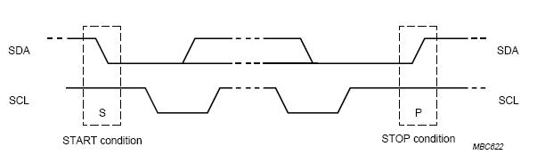
Fig.1 START and STOP Conditions
Notes:
START and STOP conditions are always generated by the master. The bus is considered to be busy after the START condition. The bus is considered to be free again a certain time after the STOP condition.
Transferring data
1. Every byte put on the SDA line must be 8-bits long. The number of bytes that can be transmitted per transfer is unrestricted.
2. Each byte has to be followed by an acknowledge bit.
3. Data is transferred with the most significant bit (MSB) first.
4. Data transfer with acknowledge is obligatory. The acknowledge-related clock pulse is generated by the master.
5. The acknowledge-related clock pulse is generated by the master. The transmitter releases the SDA line (HIGH) during the acknowledge clock pulse.
6. The receiver must pull down the SDA line during the acknowledge clock pulse
7. If a slave-receiver does acknowledge the slave address but, some time later in the transfer cannot receive any more data bytes, the master must again abort the transfer. This is indicated by the slave generating the NACK on the first byte to follow. The slave leaves the data line HIGH and the master generates a STOP or a repeated START condition.
If a master-receiver is involved in a transfer, it must signal the end of data to the slave-transmitter by not generating an ACK on the last byte that was clocked out of the slave. The slave-transmitter must release the data line to allow the master to generate a STOP or repeated START condition.


 126
126

 被折叠的 条评论
为什么被折叠?
被折叠的 条评论
为什么被折叠?
 到【灌水乐园】发言


