


1、背景
需要采集功率表的功率及电量数据,考虑采用ESP32采集数据后发送给服务器。
所需硬件:ESP32开发板、485从机、232转485芯片。
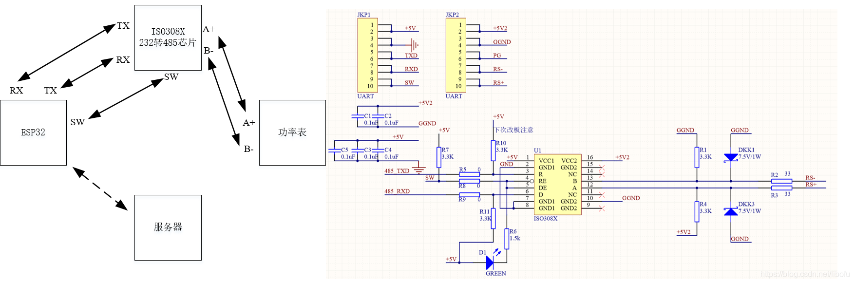
图1、连接示意图
2、实现
数字功率表采用Modbus RTU模式进行数据的传输,通过查看附带的说明书可以知道,数据的传输格式,1个起始位,8个数据位,2个停止位,在编程时需要使用。下面使用ESP32读取数字功率表的通讯地址。
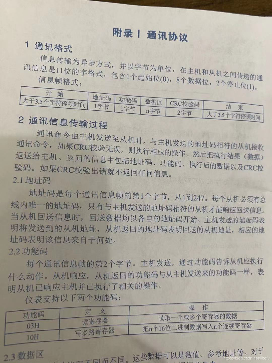
图2、数显功率表的通信格式
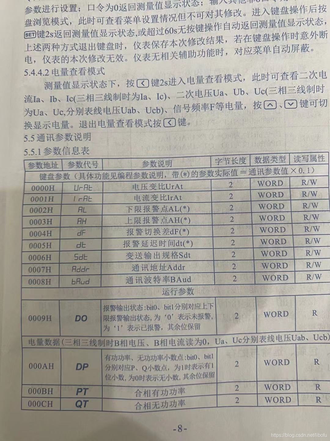
图3、数显功率表读取信息地址
通过说明书可以得知我们的通讯格式为:0x02,0x03,0x00,0x08,0x00,0x01,0x05,0xFB
0x02:通讯从机地址,是我们自己设置的数显功率表通讯地址。
0x03:命令字,读数显功率表寄存器。
0x00,0x08:需要读取的寄存器起始地址,从图3中可以看出,读波特率为0x0008。
0x00,0x01:需要读取的寄存器数量,我们只读取0x0008开始的一个字节的数据。
0x05,0xFB:CRC校验和。
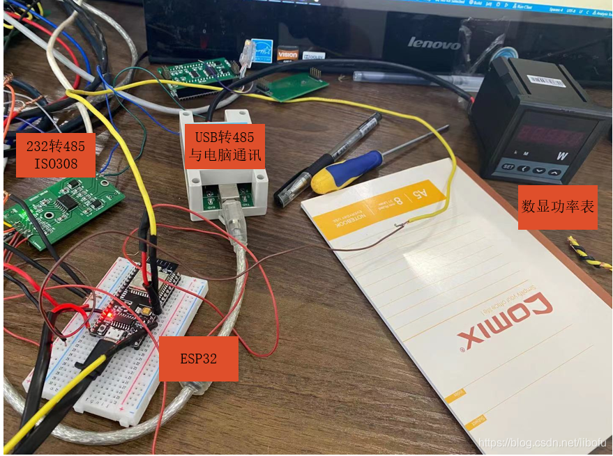
图4连接方式
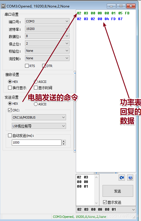
图5数据收发
上图中使用电脑通过USB转485方式与功率表通信,读取波特率设置值。
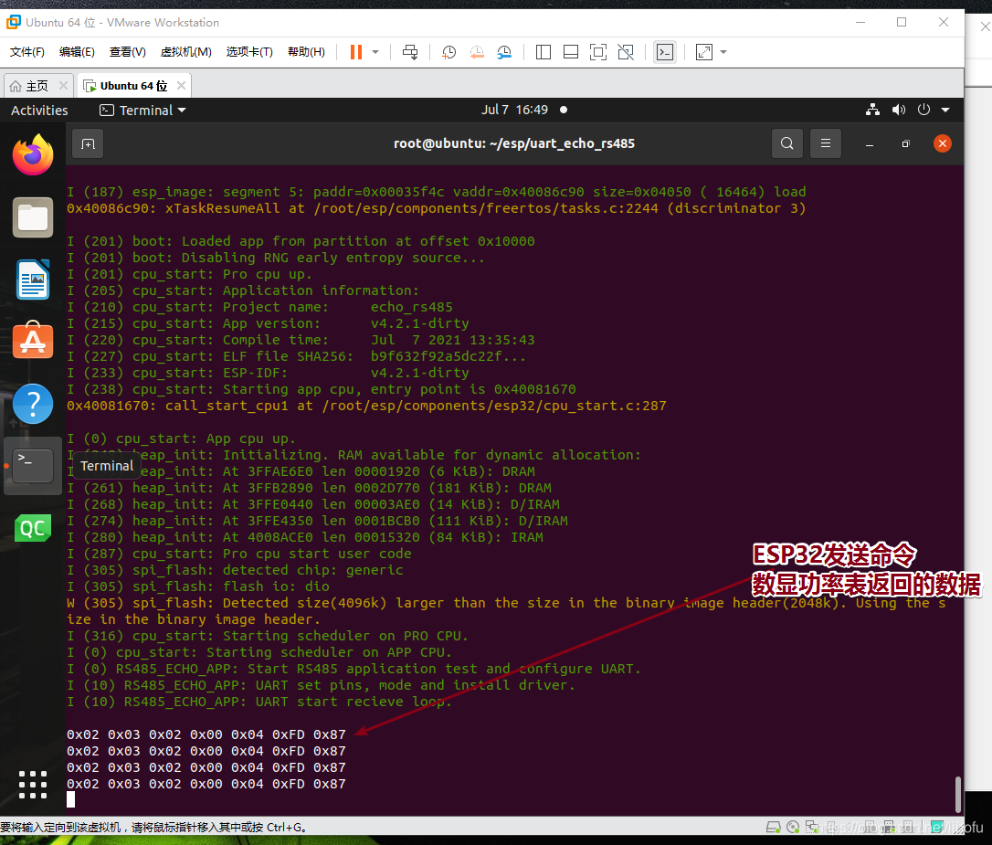
图6、测试使用ESP32发送命令
从上图中能发现数显功率表一直在返回波特率的设置值,程序中是一直发送固定的命令,下面为全部的代码。
3、代码
参考代码为乐鑫ESP32 SDK:https://www.espressif.com/zh-hans/support/download/sdks-demos?keys=&field_type_tid%5B%5D=624&field_type_tid%5B%5D=13
程序目录为:examples/peripherals/uart/uart_echo_rs485/
/* Uart Events Example

   This example code is in the Public Domain (or CC0 licensed, at your option.)

   Unless required by applicable law or agreed to in writing, this
   software is distributed on an "AS IS" BASIS, WITHOUT WARRANTIES OR
   CONDITIONS OF ANY KIND, either express or implied.
*/
#include <stdio.h>
#include <string.h>
#include <stdlib.h>
#include "freertos/FreeRTOS.h"
#include "freertos/task.h"
#include "esp_system.h"
#include "nvs_flash.h"
#include "driver/uart.h"
#include "freertos/queue.h"
#include "esp_log.h"
#include "sdkconfig.h"
#include "driver/gpio.h"

/**
 * This is a example which echos any data it receives on UART back to the sender using RS485 interface in half duplex mode.
*/
#define TAG "RS485_ECHO_APP"

// Note: Some pins on target chip cannot be assigned for UART communication.
// Please refer to documentation for selected board and target to configure pins using Kconfig.
#define ECHO_TEST_TXD   (CONFIG_ECHO_UART_TXD)
#define ECHO_TEST_RXD   (CONFIG_ECHO_UART_RXD)

// RTS for RS485 Half-Duplex Mode manages DE/~RE
#define ECHO_TEST_RTS   (CONFIG_ECHO_UART_RTS)

// CTS is not used in RS485 Half-Duplex Mode
#define ECHO_TEST_CTS   (UART_PIN_NO_CHANGE)

#define BUF_SIZE        (127)
#define BAUD_RATE       (CONFIG_ECHO_UART_BAUD_RATE)

// Read packet timeout
#define PACKET_READ_TICS        (100 / portTICK_RATE_MS)
#define ECHO_TASK_STACK_SIZE    (2048)
#define ECHO_TASK_PRIO          (10)
#define ECHO_UART_PORT          (CONFIG_ECHO_UART_PORT_NUM)

// Timeout threshold for UART = number of symbols (~10 tics) with unchanged state on receive pin
#define ECHO_READ_TOUT          (3) // 3.5T * 8 = 28 ticks, TOUT=3 -> ~24..33 ticks

static void echo_send(const int port, const char * str, uint8_t length)
{
    if (uart_write_bytes(port, str, length) != length) {
        ESP_LOGE(TAG, "Send data critical failure.");
        // add your code to handle sending failure here
        abort();
    }
}

// An example of echo test with hardware flow control on UART
static void echo_task(void *arg)
{
    const int uart_num = ECHO_UART_PORT;
    uart_config_t uart_config = { //串口信息配置,需要与从机的通讯协议一致
        .baud_rate = BAUD_RATE,
        .data_bits = UART_DATA_8_BITS,
        .parity = UART_PARITY_DISABLE,
        .stop_bits = UART_STOP_BITS_2,
        .flow_ctrl = UART_HW_FLOWCTRL_DISABLE,
        .rx_flow_ctrl_thresh = 122,
        .source_clk = UART_SCLK_APB,
    };

    // Set UART log level
    esp_log_level_set(TAG, ESP_LOG_INFO);

    ESP_LOGI(TAG, "Start RS485 application test and configure UART.");

    // Install UART driver (we don't need an event queue here)
    // In this example we don't even use a buffer for sending data.
    ESP_ERROR_CHECK(uart_driver_install(uart_num, BUF_SIZE * 2, 0, 0, NULL, 0));

    // Configure UART parameters
    ESP_ERROR_CHECK(uart_param_config(uart_num, &uart_config));

    ESP_LOGI(TAG, "UART set pins, mode and install driver.");

    // Set UART pins as per KConfig settings
    ESP_ERROR_CHECK(uart_set_pin(uart_num, ECHO_TEST_TXD, ECHO_TEST_RXD, ECHO_TEST_RTS, ECHO_TEST_CTS));

    // Set RS485 half duplex mode
    ESP_ERROR_CHECK(uart_set_mode(uart_num, UART_MODE_RS485_HALF_DUPLEX));

    // Set read timeout of UART TOUT feature
    ESP_ERROR_CHECK(uart_set_rx_timeout(uart_num, ECHO_READ_TOUT));

    // Allocate buffers for UART
    //uint8_t* data = (uint8_t*) malloc(BUF_SIZE);
    uint8_t data[] = {0x02,0x03,0x00,0x08,0x00,0x01,0x05,0xFB}; //固定的命令
    uint8_t recbuf[128]={0x00};//接收数据变量
    ESP_LOGI(TAG, "UART start recieve loop.\r\n");

    while(1) {
      gpio_set_level(16,0);
      echo_send(uart_num, (const char*)data, 8);
	  gpio_set_level(16,1);

      vTaskDelay(200 / portTICK_PERIOD_MS);
	  int len = uart_read_bytes(uart_num, recbuf, 128, PACKET_READ_TICS);
	if(len>0)
	{
		//printf("recv data len=%d\n",len);
         for(int i=0;i<len;i++)
	 {
	 	printf("0x%.2X ", (uint8_t)recbuf[i]);//打印收到的数据
	 }
	}
                printf("\n");
	vTaskDelay(3000 / portTICK_PERIOD_MS);//每个3s查询一次数据
    }
    vTaskDelete(NULL);
}

void app_main(void)
{
    //GPIO16脚为控制引脚,控制数据的收发方向
	gpio_pad_select_gpio(16); //
    gpio_set_direction(16, GPIO_MODE_OUTPUT);
    //A uart read/write example without event queue;
    xTaskCreate(echo_task, "uart_echo_task", ECHO_TASK_STACK_SIZE, NULL, ECHO_TASK_PRIO, NULL);//创建任务
}
只是做了最简单的命令收发,希望对大家有帮助。


 3023
3023

 被折叠的 条评论
为什么被折叠?
被折叠的 条评论
为什么被折叠?
 到【灌水乐园】发言


