


想把最近在esp32-s3上移植lvgl的过程记录下来,方便后面学习。
目录
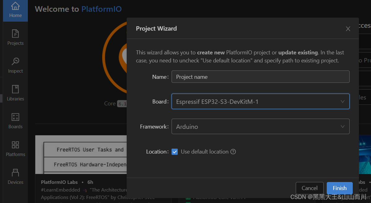
一、创建新工程
使用platformIO创建新工程
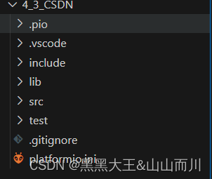 创建好工程后点击platformio.ini进入芯片设置
把原本的
[env:esp32-s3-devkitm-1]
platform = espressif32
board = esp32-s3-devkitm-1
framework = arduino
改为自己的(因为我的是N16R8型号)
[env:esp32-s3-devkitc-1]
platform = espressif32
board = esp32-s3-devkitc-1
framework = arduino
; 指定为16MB的FLASH分区表
board_build.arduino.partitions = default_16MB.csv
; 指定FLASH和PSRAM的运行模式
board_build.arduino.memory_type = qio_opi
; 预定义宏,启用PSRAM
build_flags = -DBOARD_HAS_PSRAM
; 指定FLASH容量为16MB
board_upload.flash_size = 16MB
阅读lib文件夹下的readme文件
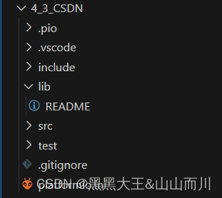
发现官方推荐的文件结构为在lib文件夹下新建文件夹,然后在这个文件夹下再新建.h.c文件(外设可以放在此文件夹,就不会出现在main里面找不到头文件的情况了)

二、导入和配置库
1、导入TFT_eSPI库

在platformio的菜单栏 点击libraries输入TFT_eSPI搜索
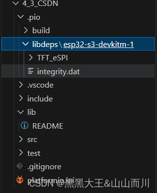
再点击Add to project保存到工程下面(注意,是保存到刚刚创建的工程下面,不要保存错位置了)
成功添加后platformio.ini.文件下会出现添加的什么库,什么版本
[env:esp32-s3-devkitm-1]
platform = espressif32
board = esp32-s3-devkitm-1
framework = arduino
lib_deps = bodmer/TFT_eSPI@^2.5.43
下面的文件夹也会出现TFT库的情况
2、配置TFT_eSPI库

值得注意的是上图最下面的两个文件:User_Setup.h和User_Setup_Select.h文件,这两个文件将配置屏幕引脚(我看别人都是两个配置一个都行,但是我选择都配置,哦对了,我的屏幕不带触摸)
点开User_Setup.h:
修改前内容为:
//                            USER DEFINED SETTINGS
//   Set driver type, fonts to be loaded, pins used and SPI control method etc.
//
//   See the User_Setup_Select.h file if you wish to be able to define multiple
//   setups and then easily select which setup file is used by the compiler.
//
//   If this file is edited correctly then all the library example sketches should
//   run without the need to make any more changes for a particular hardware setup!
//   Note that some sketches are designed for a particular TFT pixel width/height

// User defined information reported by "Read_User_Setup" test & diagnostics example
#define USER_SETUP_INFO "User_Setup"

// Define to disable all #warnings in library (can be put in User_Setup_Select.h)
//#define DISABLE_ALL_LIBRARY_WARNINGS

// ##################################################################################
//
// Section 1. Call up the right driver file and any options for it
//
// ##################################################################################

// Define STM32 to invoke optimised processor support (only for STM32)
//#define STM32

// Defining the STM32 board allows the library to optimise the performance
// for UNO compatible "MCUfriend" style shields
//#define NUCLEO_64_TFT
//#define NUCLEO_144_TFT

// STM32 8-bit parallel only:
// If STN32 Port A or B pins 0-7 are used for 8-bit parallel data bus bits 0-7
// then this will improve rendering performance by a factor of ~8x
//#define STM_PORTA_DATA_BUS
//#define STM_PORTB_DATA_BUS

// Tell the library to use parallel mode (otherwise SPI is assumed)
//#define TFT_PARALLEL_8_BIT
//#defined TFT_PARALLEL_16_BIT // **** 16-bit parallel ONLY for RP2040 processor ****

// Display type -  only define if RPi display
//#define RPI_DISPLAY_TYPE // 20MHz maximum SPI

// Only define one driver, the other ones must be commented out
#define ILI9341_DRIVER       // Generic driver for common displays
//#define ILI9341_2_DRIVER     // Alternative ILI9341 driver, see https://github.com/Bodmer/TFT_eSPI/issues/1172
//#define ST7735_DRIVER      // Define additional parameters below for this display
//#define ILI9163_DRIVER     // Define additional parameters below for this display
//#define S6D02A1_DRIVER
//#define RPI_ILI9486_DRIVER // 20MHz maximum SPI
//#define HX8357D_DRIVER
//#define ILI9481_DRIVER
//#define ILI9486_DRIVER
//#define ILI9488_DRIVER     // WARNING: Do not connect ILI9488 display SDO to MISO if other devices share the SPI bus (TFT SDO does NOT tristate when CS is high)
//#define ST7789_DRIVER      // Full configuration option, define additional parameters below for this display
//#define ST7789_2_DRIVER    // Minimal configuration option, define additional parameters below for this display
//#define R61581_DRIVER
//#define RM68140_DRIVER
//#define ST7796_DRIVER
//#define SSD1351_DRIVER
//#define SSD1963_480_DRIVER
//#define SSD1963_800_DRIVER
//#define SSD1963_800ALT_DRIVER
//#define ILI9225_DRIVER
//#define GC9A01_DRIVER

// Some displays support SPI reads via the MISO pin, other displays have a single
// bi-directional SDA pin and the library will try to read this via the MOSI line.
// To use the SDA line for reading data from the TFT uncomment the following line:

// #define TFT_SDA_READ      // This option is for ESP32 ONLY, tested with ST7789 and GC9A01 display only

// For ST7735, ST7789 and ILI9341 ONLY, define the colour order IF the blue and red are swapped on your display
// Try ONE option at a time to find the correct colour order for your display

//  #define TFT_RGB_ORDER TFT_RGB  // Colour order Red-Green-Blue
//  #define TFT_RGB_ORDER TFT_BGR  // Colour order Blue-Green-Red

// For M5Stack ESP32 module with integrated ILI9341 display ONLY, remove // in line below

// #define M5STACK

// For ST7789, ST7735, ILI9163 and GC9A01 ONLY, define the pixel width and height in portrait orientation
// #define TFT_WIDTH  80
// #define TFT_WIDTH  128
// #define TFT_WIDTH  172 // ST7789 172 x 320
// #define TFT_WIDTH  170 // ST7789 170 x 320
// #define TFT_WIDTH  240 // ST7789 240 x 240 and 240 x 320
// #define TFT_HEIGHT 160
// #define TFT_HEIGHT 128
// #define TFT_HEIGHT 240 // ST7789 240 x 240
// #define TFT_HEIGHT 320 // ST7789 240 x 320
// #define TFT_HEIGHT 240 // GC9A01 240 x 240

// For ST7735 ONLY, define the type of display, originally this was based on the
// colour of the tab on the screen protector film but this is not always true, so try
// out the different options below if the screen does not display graphics correctly,
// e.g. colours wrong, mirror images, or stray pixels at the edges.
// Comment out ALL BUT ONE of these options for a ST7735 display driver, save this
// this User_Setup file, then rebuild and upload the sketch to the board again:

// #define ST7735_INITB
// #define ST7735_GREENTAB
// #define ST7735_GREENTAB2
// #define ST7735_GREENTAB3
// #define ST7735_GREENTAB128    // For 128 x 128 display
// #define ST7735_GREENTAB160x80 // For 160 x 80 display (BGR, inverted, 26 offset)
// #define ST7735_ROBOTLCD       // For some RobotLCD Arduino shields (128x160, BGR, https://docs.arduino.cc/retired/getting-started-guides/TFT)
// #define ST7735_REDTAB
// #define ST7735_BLACKTAB
// #define ST7735_REDTAB160x80   // For 160 x 80 display with 24 pixel offset

// If colours are inverted (white shows as black) then uncomment one of the next
// 2 lines try both options, one of the options should correct the inversion.

// #define TFT_INVERSION_ON
// #define TFT_INVERSION_OFF


// ##################################################################################
//
// Section 2. Define the pins that are used to interface with the display here
//
// ##################################################################################

// If a backlight control signal is available then define the TFT_BL pin in Section 2
// below. The backlight will be turned ON when tft.begin() is called, but the library
// needs to know if the LEDs are ON with the pin HIGH or LOW. If the LEDs are to be
// driven with a PWM signal or turned OFF/ON then this must be handled by the user
// sketch. e.g. with digitalWrite(TFT_BL, LOW);

// #define TFT_BL   32            // LED back-light control pin
// #define TFT_BACKLIGHT_ON HIGH  // Level to turn ON back-light (HIGH or LOW)


// We must use hardware SPI, a minimum of 3 GPIO pins is needed.
// Typical setup for ESP8266 NodeMCU ESP-12 is :
//
// Display SDO/MISO  to NodeMCU pin D6 (or leave disconnected if not reading TFT)
// Display LED       to NodeMCU pin VIN (or 5V, see below)
// Display SCK       to NodeMCU pin D5
// Display SDI/MOSI  to NodeMCU pin D7
// Display DC (RS/AO)to NodeMCU pin D3
// Display RESET     to NodeMCU pin D4 (or RST, see below)
// Display CS        to NodeMCU pin D8 (or GND, see below)
// Display GND       to NodeMCU pin GND (0V)
// Display VCC       to NodeMCU 5V or 3.3V
//
// The TFT RESET pin can be connected to the NodeMCU RST pin or 3.3V to free up a control pin
//
// The DC (Data Command) pin may be labelled AO or RS (Register Select)
//
// With some displays such as the ILI9341 the TFT CS pin can be connected to GND if no more
// SPI devices (e.g. an SD Card) are connected, in this case comment out the #define TFT_CS
// line below so it is NOT defined. Other displays such at the ST7735 require the TFT CS pin
// to be toggled during setup, so in these cases the TFT_CS line must be defined and connected.
//
// The NodeMCU D0 pin can be used for RST
//
//
// Note: only some versions of the NodeMCU provide the USB 5V on the VIN pin
// If 5V is not available at a pin you can use 3.3V but backlight brightness
// will be lower.


// ###### EDIT THE PIN NUMBERS IN THE LINES FOLLOWING TO SUIT YOUR ESP8266 SETUP ######

// For NodeMCU - use pin numbers in the form PIN_Dx where Dx is the NodeMCU pin designation
#define TFT_MISO  PIN_D6  // Automatically assigned with ESP8266 if not defined
#define TFT_MOSI  PIN_D7  // Automatically assigned with ESP8266 if not defined
#define TFT_SCLK  PIN_D5  // Automatically assigned with ESP8266 if not defined

#define TFT_CS    PIN_D8  // Chip select control pin D8
#define TFT_DC    PIN_D3  // Data Command control pin
#define TFT_RST   PIN_D4  // Reset pin (could connect to NodeMCU RST, see next line)
//#define TFT_RST  -1     // Set TFT_RST to -1 if the display RESET is connected to NodeMCU RST or 3.3V


//#define TFT_BL PIN_D1  // LED back-light (only for ST7789 with backlight control pin)

//#define TOUCH_CS PIN_D2     // Chip select pin (T_CS) of touch screen

//#define TFT_WR PIN_D2       // Write strobe for modified Raspberry Pi TFT only


// ######  FOR ESP8266 OVERLAP MODE EDIT THE PIN NUMBERS IN THE FOLLOWING LINES  ######

// Overlap mode shares the ESP8266 FLASH SPI bus with the TFT so has a performance impact
// but saves pins for other functions. It is best not to connect MISO as some displays
// do not tristate that line when chip select is high!
// Note: Only one SPI device can share the FLASH SPI lines, so a SPI touch controller
// cannot be connected as well to the same SPI signals.
// On NodeMCU 1.0 SD0=MISO, SD1=MOSI, CLK=SCLK to connect to TFT in overlap mode
// On NodeMCU V3  S0 =MISO, S1 =MOSI, S2 =SCLK
// In ESP8266 overlap mode the following must be defined

//#define TFT_SPI_OVERLAP

// In ESP8266 overlap mode the TFT chip select MUST connect to pin D3
//#define TFT_CS   PIN_D3
//#define TFT_DC   PIN_D5  // Data Command control pin
//#define TFT_RST  PIN_D4  // Reset pin (could connect to NodeMCU RST, see next line)
//#define TFT_RST  -1  // Set TFT_RST to -1 if the display RESET is connected to NodeMCU RST or 3.3V


// ###### EDIT THE PIN NUMBERS IN THE LINES FOLLOWING TO SUIT YOUR ESP32 SETUP   ######

// For ESP32 Dev board (only tested with ILI9341 display)
// The hardware SPI can be mapped to any pins

//#define TFT_MISO 19
//#define TFT_MOSI 23
//#define TFT_SCLK 18
//#define TFT_CS   15  // Chip select control pin
//#define TFT_DC    2  // Data Command control pin
//#define TFT_RST   4  // Reset pin (could connect to RST pin)
//#define TFT_RST  -1  // Set TFT_RST to -1 if display RESET is connected to ESP32 board RST

// For ESP32 Dev board (only tested with GC9A01 display)
// The hardware SPI can be mapped to any pins

//#define TFT_MOSI 15 // In some display driver board, it might be written as "SDA" and so on.
//#define TFT_SCLK 14
//#define TFT_CS   5  // Chip select control pin
//#define TFT_DC   27  // Data Command control pin
//#define TFT_RST  33  // Reset pin (could connect to Arduino RESET pin)
//#define TFT_BL   22  // LED back-light

//#define TOUCH_CS 21     // Chip select pin (T_CS) of touch screen

//#define TFT_WR 22    // Write strobe for modified Raspberry Pi TFT only

// For the M5Stack module use these #define lines
//#define TFT_MISO 19
//#define TFT_MOSI 23
//#define TFT_SCLK 18
//#define TFT_CS   14  // Chip select control pin
//#define TFT_DC   27  // Data Command control pin
//#define TFT_RST  33  // Reset pin (could connect to Arduino RESET pin)
//#define TFT_BL   32  // LED back-light (required for M5Stack)

// ######       EDIT THE PINs BELOW TO SUIT YOUR ESP32 PARALLEL TFT SETUP        ######

// The library supports 8-bit parallel TFTs with the ESP32, the pin
// selection below is compatible with ESP32 boards in UNO format.
// Wemos D32 boards need to be modified, see diagram in Tools folder.
// Only ILI9481 and ILI9341 based displays have been tested!

// Parallel bus is only supported for the STM32 and ESP32
// Example below is for ESP32 Parallel interface with UNO displays

// Tell the library to use 8-bit parallel mode (otherwise SPI is assumed)
//#define TFT_PARALLEL_8_BIT

// The ESP32 and TFT the pins used for testing are:
//#define TFT_CS   33  // Chip select control pin (library pulls permanently low
//#define TFT_DC   15  // Data Command control pin - must use a pin in the range 0-31
//#define TFT_RST  32  // Reset pin, toggles on startup

//#define TFT_WR    4  // Write strobe control pin - must use a pin in the range 0-31
//#define TFT_RD    2  // Read strobe control pin

//#define TFT_D0   12  // Must use pins in the range 0-31 for the data bus
//#define TFT_D1   13  // so a single register write sets/clears all bits.
//#define TFT_D2   26  // Pins can be randomly assigned, this does not affect
//#define TFT_D3   25  // TFT screen update performance.
//#define TFT_D4   17
//#define TFT_D5   16
//#define TFT_D6   27
//#define TFT_D7   14

// ######       EDIT THE PINs BELOW TO SUIT YOUR STM32 SPI TFT SETUP        ######

// The TFT can be connected to SPI port 1 or 2
//#define TFT_SPI_PORT 1 // SPI port 1 maximum clock rate is 55MHz
//#define TFT_MOSI PA7
//#define TFT_MISO PA6
//#define TFT_SCLK PA5

//#define TFT_SPI_PORT 2 // SPI port 2 maximum clock rate is 27MHz
//#define TFT_MOSI PB15
//#define TFT_MISO PB14
//#define TFT_SCLK PB13

// Can use Ardiuno pin references, arbitrary allocation, TFT_eSPI controls chip select
//#define TFT_CS   D5 // Chip select control pin to TFT CS
//#define TFT_DC   D6 // Data Command control pin to TFT DC (may be labelled RS = Register Select)
//#define TFT_RST  D7 // Reset pin to TFT RST (or RESET)
// OR alternatively, we can use STM32 port reference names PXnn
//#define TFT_CS   PE11 // Nucleo-F767ZI equivalent of D5
//#define TFT_DC   PE9  // Nucleo-F767ZI equivalent of D6
//#define TFT_RST  PF13 // Nucleo-F767ZI equivalent of D7

//#define TFT_RST  -1   // Set TFT_RST to -1 if the display RESET is connected to processor reset
                        // Use an Arduino pin for initial testing as connecting to processor reset
                        // may not work (pulse too short at power up?)

// ##################################################################################
//
// Section 3. Define the fonts that are to be used here
//
// ##################################################################################

// Comment out the #defines below with // to stop that font being loaded
// The ESP8366 and ESP32 have plenty of memory so commenting out fonts is not
// normally necessary. If all fonts are loaded the extra FLASH space required is
// about 17Kbytes. To save FLASH space only enable the fonts you need!

#define LOAD_GLCD   // Font 1. Original Adafruit 8 pixel font needs ~1820 bytes in FLASH
#define LOAD_FONT2  // Font 2. Small 16 pixel high font, needs ~3534 bytes in FLASH, 96 characters
#define LOAD_FONT4  // Font 4. Medium 26 pixel high font, needs ~5848 bytes in FLASH, 96 characters
#define LOAD_FONT6  // Font 6. Large 48 pixel font, needs ~2666 bytes in FLASH, only characters 1234567890:-.apm
#define LOAD_FONT7  // Font 7. 7 segment 48 pixel font, needs ~2438 bytes in FLASH, only characters 1234567890:-.
#define LOAD_FONT8  // Font 8. Large 75 pixel font needs ~3256 bytes in FLASH, only characters 1234567890:-.
//#define LOAD_FONT8N // Font 8. Alternative to Font 8 above, slightly narrower, so 3 digits fit a 160 pixel TFT
#define LOAD_GFXFF  // FreeFonts. Include access to the 48 Adafruit_GFX free fonts FF1 to FF48 and custom fonts

// Comment out the #define below to stop the SPIFFS filing system and smooth font code being loaded
// this will save ~20kbytes of FLASH
#define SMOOTH_FONT


// ##################################################################################
//
// Section 4. Other options
//
// ##################################################################################

// For RP2040 processor and SPI displays, uncomment the following line to use the PIO interface.
//#define RP2040_PIO_SPI // Leave commented out to use standard RP2040 SPI port interface

// For RP2040 processor and 8 or 16-bit parallel displays:
// The parallel interface write cycle period is derived from a division of the CPU clock
// speed so scales with the processor clock. This means that the divider ratio may need
// to be increased when overclocking. It may also need to be adjusted dependant on the
// display controller type (ILI94341, HX8357C etc.). If RP2040_PIO_CLK_DIV is not defined
// the library will set default values which may not suit your display.
// The display controller data sheet will specify the minimum write cycle period. The
// controllers often work reliably for shorter periods, however if the period is too short
// the display may not initialise or graphics will become corrupted.
// PIO write cycle frequency = (CPU clock/(4 * RP2040_PIO_CLK_DIV))
//#define RP2040_PIO_CLK_DIV 1 // 32ns write cycle at 125MHz CPU clock
//#define RP2040_PIO_CLK_DIV 2 // 64ns write cycle at 125MHz CPU clock
//#define RP2040_PIO_CLK_DIV 3 // 96ns write cycle at 125MHz CPU clock

// For the RP2040 processor define the SPI port channel used (default 0 if undefined)
//#define TFT_SPI_PORT 1 // Set to 0 if SPI0 pins are used, or 1 if spi1 pins used

// For the STM32 processor define the SPI port channel used (default 1 if undefined)
//#define TFT_SPI_PORT 2 // Set to 1 for SPI port 1, or 2 for SPI port 2

// Define the SPI clock frequency, this affects the graphics rendering speed. Too
// fast and the TFT driver will not keep up and display corruption appears.
// With an ILI9341 display 40MHz works OK, 80MHz sometimes fails
// With a ST7735 display more than 27MHz may not work (spurious pixels and lines)
// With an ILI9163 display 27 MHz works OK.

// #define SPI_FREQUENCY   1000000
// #define SPI_FREQUENCY   5000000
// #define SPI_FREQUENCY  10000000
// #define SPI_FREQUENCY  20000000
#define SPI_FREQUENCY  27000000
// #define SPI_FREQUENCY  40000000
// #define SPI_FREQUENCY  55000000 // STM32 SPI1 only (SPI2 maximum is 27MHz)
// #define SPI_FREQUENCY  80000000

// Optional reduced SPI frequency for reading TFT
#define SPI_READ_FREQUENCY  20000000

// The XPT2046 requires a lower SPI clock rate of 2.5MHz so we define that here:
#define SPI_TOUCH_FREQUENCY  2500000

// The ESP32 has 2 free SPI ports i.e. VSPI and HSPI, the VSPI is the default.
// If the VSPI port is in use and pins are not accessible (e.g. TTGO T-Beam)
// then uncomment the following line:
//#define USE_HSPI_PORT

// Comment out the following #define if "SPI Transactions" do not need to be
// supported. When commented out the code size will be smaller and sketches will
// run slightly faster, so leave it commented out unless you need it!

// Transaction support is needed to work with SD library but not needed with TFT_SdFat
// Transaction support is required if other SPI devices are connected.

// Transactions are automatically enabled by the library for an ESP32 (to use HAL mutex)
// so changing it here has no effect

// #define SUPPORT_TRANSACTIONS
修改后:
//                            USER DEFINED SETTINGS
//   Set driver type, fonts to be loaded, pins used and SPI control method etc.
//
//   See the User_Setup_Select.h file if you wish to be able to define multiple
//   setups and then easily select which setup file is used by the compiler.
//
//   If this file is edited correctly then all the library example sketches should
//   run without the need to make any more changes for a particular hardware setup!
//   Note that some sketches are designed for a particular TFT pixel width/height

// User defined information reported by "Read_User_Setup" test & diagnostics example
#define USER_SETUP_INFO "User_Setup"

// Define to disable all #warnings in library (can be put in User_Setup_Select.h)
//#define DISABLE_ALL_LIBRARY_WARNINGS

// ##################################################################################
//
// Section 1. Call up the right driver file and any options for it
//
// ##################################################################################

// Define STM32 to invoke optimised processor support (only for STM32)
//#define STM32

// Defining the STM32 board allows the library to optimise the performance
// for UNO compatible "MCUfriend" style shields
//#define NUCLEO_64_TFT
//#define NUCLEO_144_TFT

// STM32 8-bit parallel only:
// If STN32 Port A or B pins 0-7 are used for 8-bit parallel data bus bits 0-7
// then this will improve rendering performance by a factor of ~8x
//#define STM_PORTA_DATA_BUS
//#define STM_PORTB_DATA_BUS

// Tell the library to use parallel mode (otherwise SPI is assumed)
//#define TFT_PARALLEL_8_BIT
//#defined TFT_PARALLEL_16_BIT // **** 16-bit parallel ONLY for RP2040 processor ****

// Display type -  only define if RPi display
//#define RPI_DISPLAY_TYPE // 20MHz maximum SPI

// Only define one driver, the other ones must be commented out
//#define ILI9341_DRIVER       // Generic driver for common displays
//#define ILI9341_2_DRIVER     // Alternative ILI9341 driver, see https://github.com/Bodmer/TFT_eSPI/issues/1172
//#define ST7735_DRIVER      // Define additional parameters below for this display
//#define ILI9163_DRIVER     // Define additional parameters below for this display
//#define S6D02A1_DRIVER
//#define RPI_ILI9486_DRIVER // 20MHz maximum SPI
//#define HX8357D_DRIVER
//#define ILI9481_DRIVER
//#define ILI9486_DRIVER
//#define ILI9488_DRIVER     // WARNING: Do not connect ILI9488 display SDO to MISO if other devices share the SPI bus (TFT SDO does NOT tristate when CS is high)
//#define ST7789_DRIVER      // Full configuration option, define additional parameters below for this display
//#define ST7789_2_DRIVER    // Minimal configuration option, define additional parameters below for this display
//#define R61581_DRIVER
//#define RM68140_DRIVER
//#define ST7796_DRIVER
//#define SSD1351_DRIVER
//#define SSD1963_480_DRIVER
//#define SSD1963_800_DRIVER
//#define SSD1963_800ALT_DRIVER
//#define ILI9225_DRIVER
#define GC9A01_DRIVER

// Some displays support SPI reads via the MISO pin, other displays have a single
// bi-directional SDA pin and the library will try to read this via the MOSI line.
// To use the SDA line for reading data from the TFT uncomment the following line:

// #define TFT_SDA_READ      // This option is for ESP32 ONLY, tested with ST7789 and GC9A01 display only

// For ST7735, ST7789 and ILI9341 ONLY, define the colour order IF the blue and red are swapped on your display
// Try ONE option at a time to find the correct colour order for your display

#define TFT_RGB_ORDER TFT_RGB  // Colour order Red-Green-Blue
//  #define TFT_RGB_ORDER TFT_BGR  // Colour order Blue-Green-Red

// For M5Stack ESP32 module with integrated ILI9341 display ONLY, remove // in line below

// #define M5STACK

// For ST7789, ST7735, ILI9163 and GC9A01 ONLY, define the pixel width and height in portrait orientation
// #define TFT_WIDTH  80
// #define TFT_WIDTH  128
// #define TFT_WIDTH  172 // ST7789 172 x 320
// #define TFT_WIDTH  170 // ST7789 170 x 320
#define TFT_WIDTH  240 // ST7789 240 x 240 and 240 x 320
// #define TFT_HEIGHT 160
// #define TFT_HEIGHT 128
// #define TFT_HEIGHT 240 // ST7789 240 x 240
// #define TFT_HEIGHT 320 // ST7789 240 x 320
#define TFT_HEIGHT 240 // GC9A01 240 x 240

// For ST7735 ONLY, define the type of display, originally this was based on the
// colour of the tab on the screen protector film but this is not always true, so try
// out the different options below if the screen does not display graphics correctly,
// e.g. colours wrong, mirror images, or stray pixels at the edges.
// Comment out ALL BUT ONE of these options for a ST7735 display driver, save this
// this User_Setup file, then rebuild and upload the sketch to the board again:

// #define ST7735_INITB
// #define ST7735_GREENTAB
// #define ST7735_GREENTAB2
// #define ST7735_GREENTAB3
// #define ST7735_GREENTAB128    // For 128 x 128 display
// #define ST7735_GREENTAB160x80 // For 160 x 80 display (BGR, inverted, 26 offset)
// #define ST7735_ROBOTLCD       // For some RobotLCD Arduino shields (128x160, BGR, https://docs.arduino.cc/retired/getting-started-guides/TFT)
// #define ST7735_REDTAB
// #define ST7735_BLACKTAB
// #define ST7735_REDTAB160x80   // For 160 x 80 display with 24 pixel offset

// If colours are inverted (white shows as black) then uncomment one of the next
// 2 lines try both options, one of the options should correct the inversion.

// #define TFT_INVERSION_ON
// #define TFT_INVERSION_OFF


// ##################################################################################
//
// Section 2. Define the pins that are used to interface with the display here
//
// ##################################################################################

// If a backlight control signal is available then define the TFT_BL pin in Section 2
// below. The backlight will be turned ON when tft.begin() is called, but the library
// needs to know if the LEDs are ON with the pin HIGH or LOW. If the LEDs are to be
// driven with a PWM signal or turned OFF/ON then this must be handled by the user
// sketch. e.g. with digitalWrite(TFT_BL, LOW);

// #define TFT_BL   32            // LED back-light control pin
// #define TFT_BACKLIGHT_ON HIGH  // Level to turn ON back-light (HIGH or LOW)


// We must use hardware SPI, a minimum of 3 GPIO pins is needed.
// Typical setup for ESP8266 NodeMCU ESP-12 is :
//
// Display SDO/MISO  to NodeMCU pin D6 (or leave disconnected if not reading TFT)
// Display LED       to NodeMCU pin VIN (or 5V, see below)
// Display SCK       to NodeMCU pin D5
// Display SDI/MOSI  to NodeMCU pin D7
// Display DC (RS/AO)to NodeMCU pin D3
// Display RESET     to NodeMCU pin D4 (or RST, see below)
// Display CS        to NodeMCU pin D8 (or GND, see below)
// Display GND       to NodeMCU pin GND (0V)
// Display VCC       to NodeMCU 5V or 3.3V
//
// The TFT RESET pin can be connected to the NodeMCU RST pin or 3.3V to free up a control pin
//
// The DC (Data Command) pin may be labelled AO or RS (Register Select)
//
// With some displays such as the ILI9341 the TFT CS pin can be connected to GND if no more
// SPI devices (e.g. an SD Card) are connected, in this case comment out the #define TFT_CS
// line below so it is NOT defined. Other displays such at the ST7735 require the TFT CS pin
// to be toggled during setup, so in these cases the TFT_CS line must be defined and connected.
//
// The NodeMCU D0 pin can be used for RST
//
//
// Note: only some versions of the NodeMCU provide the USB 5V on the VIN pin
// If 5V is not available at a pin you can use 3.3V but backlight brightness
// will be lower.


// ###### EDIT THE PIN NUMBERS IN THE LINES FOLLOWING TO SUIT YOUR ESP8266 SETUP ######

// For NodeMCU - use pin numbers in the form PIN_Dx where Dx is the NodeMCU pin designation
//#define TFT_MISO  PIN_D6  // Automatically assigned with ESP8266 if not defined
//#define TFT_MOSI  PIN_D7  // Automatically assigned with ESP8266 if not defined
//#define TFT_SCLK  PIN_D5  // Automatically assigned with ESP8266 if not defined

//#define TFT_CS    PIN_D8  // Chip select control pin D8
//#define TFT_DC    PIN_D3  // Data Command control pin
//#define TFT_RST   PIN_D4  // Reset pin (could connect to NodeMCU RST, see next line)
//#define TFT_RST  -1     // Set TFT_RST to -1 if the display RESET is connected to NodeMCU RST or 3.3V


//#define TFT_BL PIN_D1  // LED back-light (only for ST7789 with backlight control pin)

//#define TOUCH_CS PIN_D2     // Chip select pin (T_CS) of touch screen

//#define TFT_WR PIN_D2       // Write strobe for modified Raspberry Pi TFT only


// ######  FOR ESP8266 OVERLAP MODE EDIT THE PIN NUMBERS IN THE FOLLOWING LINES  ######

// Overlap mode shares the ESP8266 FLASH SPI bus with the TFT so has a performance impact
// but saves pins for other functions. It is best not to connect MISO as some displays
// do not tristate that line when chip select is high!
// Note: Only one SPI device can share the FLASH SPI lines, so a SPI touch controller
// cannot be connected as well to the same SPI signals.
// On NodeMCU 1.0 SD0=MISO, SD1=MOSI, CLK=SCLK to connect to TFT in overlap mode
// On NodeMCU V3  S0 =MISO, S1 =MOSI, S2 =SCLK
// In ESP8266 overlap mode the following must be defined

//#define TFT_SPI_OVERLAP

// In ESP8266 overlap mode the TFT chip select MUST connect to pin D3
//#define TFT_CS   PIN_D3
//#define TFT_DC   PIN_D5  // Data Command control pin
//#define TFT_RST  PIN_D4  // Reset pin (could connect to NodeMCU RST, see next line)
//#define TFT_RST  -1  // Set TFT_RST to -1 if the display RESET is connected to NodeMCU RST or 3.3V


// ###### EDIT THE PIN NUMBERS IN THE LINES FOLLOWING TO SUIT YOUR ESP32 SETUP   ######

// For ESP32 Dev board (only tested with ILI9341 display)
// The hardware SPI can be mapped to any pins

//#define TFT_MISO 19
//#define TFT_MOSI 23  //SDA
//#define TFT_SCLK 18
//#define TFT_CS   15  // Chip select control pin
//#define TFT_DC    2  // Data Command control pin
//#define TFT_RST   4  // Reset pin (could connect to RST pin)
//#define TFT_RST  -1  // Set TFT_RST to -1 if display RESET is connected to ESP32 board RST

// For ESP32 Dev board (only tested with GC9A01 display)
// The hardware SPI can be mapped to any pins

#define TFT_MOSI 20 // In some display driver board, it might be written as "SDA" and so on.
#define TFT_SCLK 18
#define TFT_CS   15  // Chip select control pin
#define TFT_DC   2  // Data Command control pin
#define TFT_RST  4 // Reset pin (could connect to Arduino RESET pin)
#define TFT_BL   21  // LED back-light

//#define TOUCH_CS 21     // Chip select pin (T_CS) of touch screen

//#define TFT_WR 22    // Write strobe for modified Raspberry Pi TFT only

// For the M5Stack module use these #define lines
//#define TFT_MISO 19
//#define TFT_MOSI 23
//#define TFT_SCLK 18
//#define TFT_CS   14  // Chip select control pin
//#define TFT_DC   27  // Data Command control pin
//#define TFT_RST  33  // Reset pin (could connect to Arduino RESET pin)
//#define TFT_BL   32  // LED back-light (required for M5Stack)

// ######       EDIT THE PINs BELOW TO SUIT YOUR ESP32 PARALLEL TFT SETUP        ######

// The library supports 8-bit parallel TFTs with the ESP32, the pin
// selection below is compatible with ESP32 boards in UNO format.
// Wemos D32 boards need to be modified, see diagram in Tools folder.
// Only ILI9481 and ILI9341 based displays have been tested!

// Parallel bus is only supported for the STM32 and ESP32
// Example below is for ESP32 Parallel interface with UNO displays

// Tell the library to use 8-bit parallel mode (otherwise SPI is assumed)
//#define TFT_PARALLEL_8_BIT

// The ESP32 and TFT the pins used for testing are:
//#define TFT_CS   33  // Chip select control pin (library pulls permanently low
//#define TFT_DC   15  // Data Command control pin - must use a pin in the range 0-31
//#define TFT_RST  32  // Reset pin, toggles on startup

//#define TFT_WR    4  // Write strobe control pin - must use a pin in the range 0-31
//#define TFT_RD    2  // Read strobe control pin

//#define TFT_D0   12  // Must use pins in the range 0-31 for the data bus
//#define TFT_D1   13  // so a single register write sets/clears all bits.
//#define TFT_D2   26  // Pins can be randomly assigned, this does not affect
//#define TFT_D3   25  // TFT screen update performance.
//#define TFT_D4   17
//#define TFT_D5   16
//#define TFT_D6   27
//#define TFT_D7   14

// ######       EDIT THE PINs BELOW TO SUIT YOUR STM32 SPI TFT SETUP        ######

// The TFT can be connected to SPI port 1 or 2
//#define TFT_SPI_PORT 1 // SPI port 1 maximum clock rate is 55MHz
//#define TFT_MOSI PA7
//#define TFT_MISO PA6
//#define TFT_SCLK PA5

//#define TFT_SPI_PORT 2 // SPI port 2 maximum clock rate is 27MHz
//#define TFT_MOSI PB15
//#define TFT_MISO PB14
//#define TFT_SCLK PB13

// Can use Ardiuno pin references, arbitrary allocation, TFT_eSPI controls chip select
//#define TFT_CS   D5 // Chip select control pin to TFT CS
//#define TFT_DC   D6 // Data Command control pin to TFT DC (may be labelled RS = Register Select)
//#define TFT_RST  D7 // Reset pin to TFT RST (or RESET)
// OR alternatively, we can use STM32 port reference names PXnn
//#define TFT_CS   PE11 // Nucleo-F767ZI equivalent of D5
//#define TFT_DC   PE9  // Nucleo-F767ZI equivalent of D6
//#define TFT_RST  PF13 // Nucleo-F767ZI equivalent of D7

//#define TFT_RST  -1   // Set TFT_RST to -1 if the display RESET is connected to processor reset
                        // Use an Arduino pin for initial testing as connecting to processor reset
                        // may not work (pulse too short at power up?)

// ##################################################################################
//
// Section 3. Define the fonts that are to be used here
//
// ##################################################################################

// Comment out the #defines below with // to stop that font being loaded
// The ESP8366 and ESP32 have plenty of memory so commenting out fonts is not
// normally necessary. If all fonts are loaded the extra FLASH space required is
// about 17Kbytes. To save FLASH space only enable the fonts you need!

#define LOAD_GLCD   // Font 1. Original Adafruit 8 pixel font needs ~1820 bytes in FLASH
#define LOAD_FONT2  // Font 2. Small 16 pixel high font, needs ~3534 bytes in FLASH, 96 characters
#define LOAD_FONT4  // Font 4. Medium 26 pixel high font, needs ~5848 bytes in FLASH, 96 characters
#define LOAD_FONT6  // Font 6. Large 48 pixel font, needs ~2666 bytes in FLASH, only characters 1234567890:-.apm
#define LOAD_FONT7  // Font 7. 7 segment 48 pixel font, needs ~2438 bytes in FLASH, only characters 1234567890:-.
#define LOAD_FONT8  // Font 8. Large 75 pixel font needs ~3256 bytes in FLASH, only characters 1234567890:-.
//#define LOAD_FONT8N // Font 8. Alternative to Font 8 above, slightly narrower, so 3 digits fit a 160 pixel TFT
#define LOAD_GFXFF  // FreeFonts. Include access to the 48 Adafruit_GFX free fonts FF1 to FF48 and custom fonts

// Comment out the #define below to stop the SPIFFS filing system and smooth font code being loaded
// this will save ~20kbytes of FLASH
#define SMOOTH_FONT


// ##################################################################################
//
// Section 4. Other options
//
// ##################################################################################

// For RP2040 processor and SPI displays, uncomment the following line to use the PIO interface.
//#define RP2040_PIO_SPI // Leave commented out to use standard RP2040 SPI port interface

// For RP2040 processor and 8 or 16-bit parallel displays:
// The parallel interface write cycle period is derived from a division of the CPU clock
// speed so scales with the processor clock. This means that the divider ratio may need
// to be increased when overclocking. It may also need to be adjusted dependant on the
// display controller type (ILI94341, HX8357C etc.). If RP2040_PIO_CLK_DIV is not defined
// the library will set default values which may not suit your display.
// The display controller data sheet will specify the minimum write cycle period. The
// controllers often work reliably for shorter periods, however if the period is too short
// the display may not initialise or graphics will become corrupted.
// PIO write cycle frequency = (CPU clock/(4 * RP2040_PIO_CLK_DIV))
//#define RP2040_PIO_CLK_DIV 1 // 32ns write cycle at 125MHz CPU clock
//#define RP2040_PIO_CLK_DIV 2 // 64ns write cycle at 125MHz CPU clock
//#define RP2040_PIO_CLK_DIV 3 // 96ns write cycle at 125MHz CPU clock

// For the RP2040 processor define the SPI port channel used (default 0 if undefined)
//#define TFT_SPI_PORT 1 // Set to 0 if SPI0 pins are used, or 1 if spi1 pins used

// For the STM32 processor define the SPI port channel used (default 1 if undefined)
//#define TFT_SPI_PORT 2 // Set to 1 for SPI port 1, or 2 for SPI port 2

// Define the SPI clock frequency, this affects the graphics rendering speed. Too
// fast and the TFT driver will not keep up and display corruption appears.
// With an ILI9341 display 40MHz works OK, 80MHz sometimes fails
// With a ST7735 display more than 27MHz may not work (spurious pixels and lines)
// With an ILI9163 display 27 MHz works OK.

// #define SPI_FREQUENCY   1000000
// #define SPI_FREQUENCY   5000000
// #define SPI_FREQUENCY  10000000
// #define SPI_FREQUENCY  20000000
#define SPI_FREQUENCY  27000000
// #define SPI_FREQUENCY  40000000
// #define SPI_FREQUENCY  55000000 // STM32 SPI1 only (SPI2 maximum is 27MHz)
// #define SPI_FREQUENCY  80000000

// Optional reduced SPI frequency for reading TFT
#define SPI_READ_FREQUENCY  20000000

// The XPT2046 requires a lower SPI clock rate of 2.5MHz so we define that here:
//#define SPI_TOUCH_FREQUENCY  2500000

// The ESP32 has 2 free SPI ports i.e. VSPI and HSPI, the VSPI is the default.
// If the VSPI port is in use and pins are not accessible (e.g. TTGO T-Beam)
// then uncomment the following line:
//#define USE_HSPI_PORT

// Comment out the following #define if "SPI Transactions" do not need to be
// supported. When commented out the code size will be smaller and sketches will
// run slightly faster, so leave it commented out unless you need it!

// Transaction support is needed to work with SD library but not needed with TFT_SdFat
// Transaction support is required if other SPI devices are connected.

// Transactions are automatically enabled by the library for an ESP32 (to use HAL mutex)
// so changing it here has no effect

// #define SUPPORT_TRANSACTIONS
其实就是把适合自己屏幕型号的宏取消掉,然后找引脚配置,引脚配置可以更改引脚号的
修改 User_Setup_Select.h:
把开头的头文件注释掉,然后选自己屏幕型号的头文件
//#include <User_Setup.h> // Default setup is root library folder//#include <User_Setups/Setup42_ILI9341_ESP32.h> // Setup file for ESP32 and SPI ILI9341 240x320
//#include <User_Setups/Setup43_ST7735.h> // Setup file for ESP8266 & ESP32 configured for my ST7735S 80x160
//#include <User_Setups/Setup44_TTGO_CameraPlus.h> // Setup file for ESP32 and TTGO T-CameraPlus ST7789 SPI bus TFT 240x240
//#include <User_Setups/Setup45_TTGO_T_Watch.h> // Setup file for ESP32 and TTGO T-Watch ST7789 SPI bus TFT 240x240
#include <User_Setups/Setup46_GC9A01_ESP32.h> // Setup file for ESP32 and GC9A01 SPI bus TFT 240x240
然后鼠标悬停到这个头文件上面->转到定义,这里也是引脚配置,把它改成和上面的一致就行。
// See SetupX_Template.h for all options available
#define USER_SETUP_ID 46

#define GC9A01_DRIVER

#define TFT_MISO 19
#define TFT_MOSI 20 // In some display driver board, it might be written as "SDA" and so on.
#define TFT_SCLK 18
#define TFT_CS   15  // Chip select control pin
#define TFT_DC   2  // Data Command control pin
#define TFT_RST  4 // Reset pin (could connect to Arduino RESET pin)


#define LOAD_GLCD   // Font 1. Original Adafruit 8 pixel font needs ~1820 bytes in FLASH
#define LOAD_FONT2  // Font 2. Small 16 pixel high font, needs ~3534 bytes in FLASH, 96 characters
#define LOAD_FONT4  // Font 4. Medium 26 pixel high font, needs ~5848 bytes in FLASH, 96 characters
#define LOAD_FONT6  // Font 6. Large 48 pixel font, needs ~2666 bytes in FLASH, only characters 1234567890:-.apm
#define LOAD_FONT7  // Font 7. 7 segment 48 pixel font, needs ~2438 bytes in FLASH, only characters 1234567890:.
#define LOAD_FONT8  // Font 8. Large 75 pixel font needs ~3256 bytes in FLASH, only characters 1234567890:-.
#define LOAD_GFXFF  // FreeFonts. Include access to the 48 Adafruit_GFX free fonts FF1 to FF48 and custom fonts
#define SMOOTH_FONT

#define SPI_FREQUENCY  40000000

#define SPI_READ_FREQUENCY  20000000

#define SPI_TOUCH_FREQUENCY  2500000

// #define SUPPORT_TRANSACTIONS
其实就改这个文件就行的,User_Setup.h可以不配置
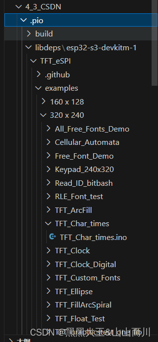
然后在TFT_eSPI文件夹下随便找一个示例代码(带ino结尾的都是),复制到main.cpp运行一下看看有没有问题(记得加上#include <Arduino.h>头文件)
In file included from .pio/libdeps/esp32-s3-devkitm-1/TFT_eSPI/TFT_eSPI.cpp:16:
.pio/libdeps/esp32-s3-devkitm-1/TFT_eSPI/TFT_eSPI.h:973:8: warning: #warning >>>>------>> TOUCH_CS pin not defined, TFT_eSPI touch functions will not be available! [-Wcpp]
       #warning >>>>------>> TOUCH_CS pin not defined, TFT_eSPI touch functions will not be available!
然后发现TOUCH报警告了,因为我没有触摸,而且没有把触摸的宏关掉,问题不大。
#define SPI_FREQUENCY  27000000
// #define SPI_FREQUENCY  40000000
// #define SPI_FREQUENCY  55000000 // STM32 SPI1 only (SPI2 maximum is 27MHz)
// #define SPI_FREQUENCY  80000000

// Optional reduced SPI frequency for reading TFT
#define SPI_READ_FREQUENCY  20000000

// The XPT2046 requires a lower SPI clock rate of 2.5MHz so we define that here:
//#define SPI_TOUCH_FREQUENCY  2500000
回到User_Setup.h最后一段,把#define SPI_TOUCH_FREQUENCY 2500000注释掉就行了,不会有警告了。
3、导入LVGL库
如上TFT流程,不详细写了。

4、配置LVGL库
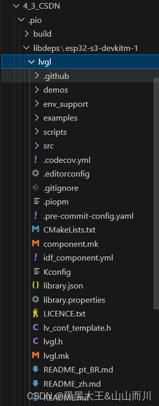
把LVGL文件夹下lv_conf_template.h复制一份,到它旁边,改名为 lv_conf.h

打开lv_conf.h文件 ,开头的#if 0改为#if 1
/* clang-format off */
#if 1 /*Set it to "1" to enable content*/

#ifndef LV_CONF_H
#define LV_CONF_H

#include <stdint.h>
第88行的#define LV_TICK_CUSTOM 0改为#define LV_TICK_CUSTOM 1(注意!!!这很重要,这是启用自己的时钟,如果没有设置,则会导致动画不能切换,帧率显示为1)
#define LV_TICK_CUSTOM 1
#if LV_TICK_CUSTOM
#define LV_TICK_CUSTOM_INCLUDE "Arduino.h" /*Header for the system time function*/
#define LV_TICK_CUSTOM_SYS_TIME_EXPR (millis()) /*Expression evaluating to current system time in ms*/
/*If using lvgl as ESP32 component*/
// #define LV_TICK_CUSTOM_INCLUDE "esp_timer.h"
// #define LV_TICK_CUSTOM_SYS_TIME_EXPR ((esp_timer_get_time() / 1000LL))
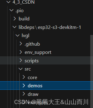
#endif /*LV_TICK_CUSTOM*/如果要跑LVGL的例程,则 demos和examples文件夹要移动到src文件夹下
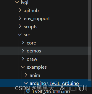
打开lvgl的例程,和TFT的例程是一样的,在examples文件夹下,把代码复制到main.cpp里面(记得加上#include <Arduino.h>头文件)
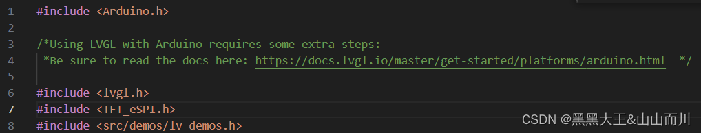
复制过来是这样的
#include <Arduino.h>

/*Using LVGL with Arduino requires some extra steps:
 *Be sure to read the docs here: https://docs.lvgl.io/master/get-started/platforms/arduino.html  */

#include <lvgl.h>
#include <TFT_eSPI.h>

/*To use the built-in examples and demos of LVGL uncomment the includes below respectively.
 *You also need to copy `lvgl/examples` to `lvgl/src/examples`. Similarly for the demos `lvgl/demos` to `lvgl/src/demos`.
 Note that the `lv_examples` library is for LVGL v7 and you shouldn't install it for this version (since LVGL v8)
 as the examples and demos are now part of the main LVGL library. */

/*Change to your screen resolution*/
static const uint16_t screenWidth  = 480;
static const uint16_t screenHeight = 320;

static lv_disp_draw_buf_t draw_buf;
static lv_color_t buf[ screenWidth * 10 ];

TFT_eSPI tft = TFT_eSPI(screenWidth, screenHeight); /* TFT instance */

#if LV_USE_LOG != 0
/* Serial debugging */
void my_print(const char * buf)
{
    Serial.printf(buf);
    Serial.flush();
}
#endif

/* Display flushing */
void my_disp_flush( lv_disp_t *disp, const lv_area_t *area, lv_color_t *color_p )
{
    uint32_t w = ( area->x2 - area->x1 + 1 );
    uint32_t h = ( area->y2 - area->y1 + 1 );

    tft.startWrite();
    tft.setAddrWindow( area->x1, area->y1, w, h );
    tft.pushColors( ( uint16_t * )&color_p->full, w * h, true );
    tft.endWrite();

    lv_disp_flush_ready( disp );
}

/*Read the touchpad*/
void my_touchpad_read( lv_indev_t * indev_driver, lv_indev_data_t * data )
{
    uint16_t touchX, touchY;

    bool touched = tft.getTouch( &touchX, &touchY, 600 );

    if( !touched )
    {
        data->state = LV_INDEV_STATE_REL;
    }
    else
    {
        data->state = LV_INDEV_STATE_PR;

        /*Set the coordinates*/
        data->point.x = touchX;
        data->point.y = touchY;

        Serial.print( "Data x " );
        Serial.println( touchX );

        Serial.print( "Data y " );
        Serial.println( touchY );
    }
}

void setup()
{
    Serial.begin( 115200 ); /* prepare for possible serial debug */

    String LVGL_Arduino = "Hello Arduino! ";
    LVGL_Arduino += String('V') + lv_version_major() + "." + lv_version_minor() + "." + lv_version_patch();

    Serial.println( LVGL_Arduino );
    Serial.println( "I am LVGL_Arduino" );

    lv_init();

#if LV_USE_LOG != 0
    lv_log_register_print_cb( my_print ); /* register print function for debugging */
#endif

    tft.begin();          /* TFT init */
    tft.setRotation( 3 ); /* Landscape orientation, flipped */

    /*Set the touchscreen calibration data,
     the actual data for your display can be acquired using
     the Generic -> Touch_calibrate example from the TFT_eSPI library*/
    uint16_t calData[5] = { 275, 3620, 264, 3532, 1 };
    tft.setTouch( calData );

    lv_disp_draw_buf_init( &draw_buf, buf, NULL, screenWidth * 10 );

    /*Initialize the display*/
    static lv_disp_t disp_drv;
    lv_disp_drv_init( &disp_drv );
    /*Change the following line to your display resolution*/
    disp_drv.hor_res = screenWidth;
    disp_drv.ver_res = screenHeight;
    disp_drv.flush_cb = my_disp_flush;
    disp_drv.draw_buf = &draw_buf;
    lv_disp_drv_register( &disp_drv );

    /*Initialize the (dummy) input device driver*/
    static lv_indev_t indev_drv;
    lv_indev_drv_init( &indev_drv );
    indev_drv.type = LV_INDEV_TYPE_POINTER;
    indev_drv.read_cb = my_touchpad_read;
    lv_indev_drv_register( &indev_drv );

#if 0
    /* Create simple label */
    lv_obj_t *label = lv_label_create( lv_scr_act() );
    lv_label_set_text( label, LVGL_Arduino.c_str() );
    lv_obj_align( label, LV_ALIGN_CENTER, 0, 0 );
#else
    /* Try an example from the lv_examples Arduino library
       make sure to include it as written above.
    lv_example_btn_1();
   */

    // uncomment one of these demos
    lv_demo_widgets();            // OK
    // lv_demo_benchmark();          // OK
    // lv_demo_keypad_encoder();     // works, but I haven't an encoder
    // lv_demo_music();              // NOK
    // lv_demo_printer();
    // lv_demo_stress();             // seems to be OK
#endif
    Serial.println( "Setup done" );
}

void loop()
{
    lv_timer_handler(); /* let the GUI do its work */
    delay( 5 );
}
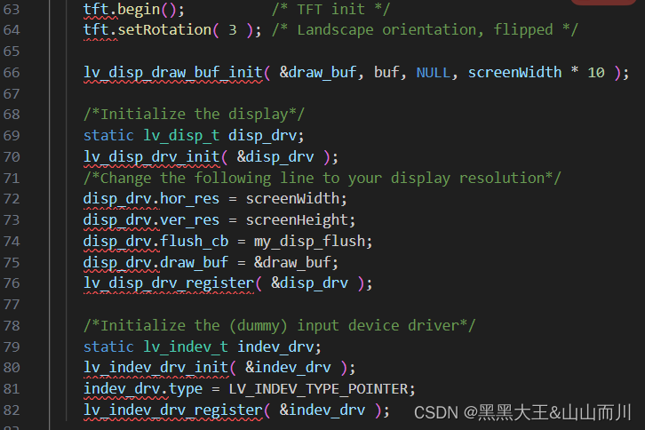
要把带touch字样的行删掉,删除后是这样的:
#include <Arduino.h>

/*Using LVGL with Arduino requires some extra steps:
 *Be sure to read the docs here: https://docs.lvgl.io/master/get-started/platforms/arduino.html  */

#include <lvgl.h>
#include <TFT_eSPI.h>

/*To use the built-in examples and demos of LVGL uncomment the includes below respectively.
 *You also need to copy `lvgl/examples` to `lvgl/src/examples`. Similarly for the demos `lvgl/demos` to `lvgl/src/demos`.
 Note that the `lv_examples` library is for LVGL v7 and you shouldn't install it for this version (since LVGL v8)
 as the examples and demos are now part of the main LVGL library. */

/*Change to your screen resolution*/
static const uint16_t screenWidth  = 480;
static const uint16_t screenHeight = 320;

static lv_disp_draw_buf_t draw_buf;
static lv_color_t buf[ screenWidth * 10 ];

TFT_eSPI tft = TFT_eSPI(screenWidth, screenHeight); /* TFT instance */

#if LV_USE_LOG != 0
/* Serial debugging */
void my_print(const char * buf)
{
    Serial.printf(buf);
    Serial.flush();
}
#endif

/* Display flushing */
void my_disp_flush( lv_disp_t *disp, const lv_area_t *area, lv_color_t *color_p )
{
    uint32_t w = ( area->x2 - area->x1 + 1 );
    uint32_t h = ( area->y2 - area->y1 + 1 );

    tft.startWrite();
    tft.setAddrWindow( area->x1, area->y1, w, h );
    tft.pushColors( ( uint16_t * )&color_p->full, w * h, true );
    tft.endWrite();

    lv_disp_flush_ready( disp );
}

}
void setup()
{
    Serial.begin( 115200 ); /* prepare for possible serial debug */

    String LVGL_Arduino = "Hello Arduino! ";
    LVGL_Arduino += String('V') + lv_version_major() + "." + lv_version_minor() + "." + lv_version_patch();

    Serial.println( LVGL_Arduino );
    Serial.println( "I am LVGL_Arduino" );

    lv_init();

#if LV_USE_LOG != 0
    lv_log_register_print_cb( my_print ); /* register print function for debugging */
#endif

    tft.begin();          /* TFT init */
    tft.setRotation( 3 ); /* Landscape orientation, flipped */

    lv_disp_draw_buf_init( &draw_buf, buf, NULL, screenWidth * 10 );

    /*Initialize the display*/
    static lv_disp_t disp_drv;
    lv_disp_drv_init( &disp_drv );
    /*Change the following line to your display resolution*/
    disp_drv.hor_res = screenWidth;
    disp_drv.ver_res = screenHeight;
    disp_drv.flush_cb = my_disp_flush;
    disp_drv.draw_buf = &draw_buf;
    lv_disp_drv_register( &disp_drv );

    /*Initialize the (dummy) input device driver*/
    static lv_indev_t indev_drv;
    lv_indev_drv_init( &indev_drv );
    indev_drv.type = LV_INDEV_TYPE_POINTER;
    lv_indev_drv_register( &indev_drv );

#if 0
    /* Create simple label */
    lv_obj_t *label = lv_label_create( lv_scr_act() );
    lv_label_set_text( label, LVGL_Arduino.c_str() );
    lv_obj_align( label, LV_ALIGN_CENTER, 0, 0 );
#else
    /* Try an example from the lv_examples Arduino library
       make sure to include it as written above.
    lv_example_btn_1();
   */

    // uncomment one of these demos
    lv_demo_widgets();            // OK
    // lv_demo_benchmark();          // OK
    // lv_demo_keypad_encoder();     // works, but I haven't an encoder
    // lv_demo_music();              // NOK
    // lv_demo_printer();
    // lv_demo_stress();             // seems to be OK
#endif
    Serial.println( "Setup done" );
}

void loop()
{
    lv_timer_handler(); /* let the GUI do its work */
    delay( 5 );
}
但是,最操蛋的来了
indev和disp报错!

右键 static lv_disp_t disp_drv; 的 lv_disp_t 进去看看类型是什么情况

发现长宽配置的结构体名字不是 lv_disp_t,而是lv_disp_drv_t!回到main.cpp,更改一下

同理,lv_indev_t也右键转到定义,然后找它的成员“type”,发现在lv_indev_drv_t里面,更改即可。

还没完,上面的打点函数也有一个disp,类型也是错误的,改为
void my_disp_flush( lv_disp_drv_t *disp, const lv_area_t *area, lv_color_t *color_p )就行了
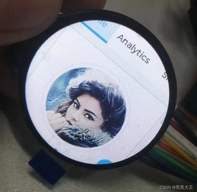
运行一下demos:

提示没有定义,那就到lv_conf.h里面搜索“widgets”
/*Show some widget. It might be required to increase `LV_MEM_SIZE` */
#define LV_USE_DEMO_WIDGETS 0
#if LV_USE_DEMO_WIDGETS
#define LV_DEMO_WIDGETS_SLIDESHOW 0
#endif
把#define LV_USE_DEMO_WIDGETS 0置1即可#define LV_USE_DEMO_WIDGETS 1
再运行一下
 报错了,看一下,原来是头文件忘记添加了,添加lv_demos.h头文件就可以了
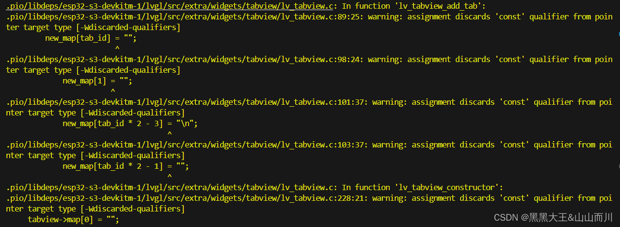
然后会发现“const”会报警告,这是因为.c和.cpp文件不同导致的,把main.cpp改为main.c 就不会报错,但是lvgl也会运行不了,所以不能这样改
 在platformio.ini文件添加 lib_ldf_mode = deep+ 这一句就行了
[env:esp32-s3-devkitm-1]
platform = espressif32
board = esp32-s3-devkitm-1
framework = arduino
lib_ldf_mode = deep+
lib_deps =
bodmer/TFT_eSPI@^2.5.43
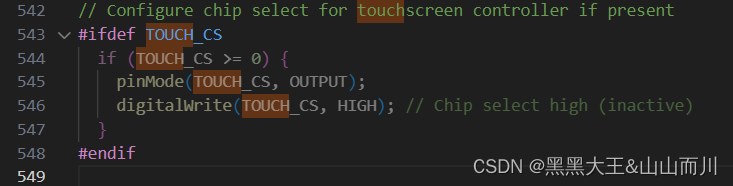
lvgl/lvgl@8.3.6发现 TOUCH还报警告,进去看看
In file included from .pio/libdeps/esp32-s3-devkitm-1/TFT_eSPI/TFT_eSPI.cpp:16:
.pio/libdeps/esp32-s3-devkitm-1/TFT_eSPI/TFT_eSPI.h:973:8: warning: #warning >>>>------>> TOUCH_CS pin not defined, TFT_eSPI touch functions will not be available! [-Wcpp]
       #warning >>>>------>> TOUCH_CS pin not defined, TFT_eSPI touch functions will not be available!
        ^~~~~~~
把TFT_eSPI.cpp的这几行删掉 就可以了
搞定


 2847
2847


 被折叠的 条评论
为什么被折叠?
被折叠的 条评论
为什么被折叠?
 到【灌水乐园】发言


