


目录
前言
本篇博客旨在给大家提供一个公交卡系统的设计思路,相关硬件以及读卡写卡的流程请参考我上一篇博客。
基于STM32的RC522模块读写数据块以及电子钱包充值扣款系统的设计
系统的结构框图
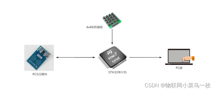
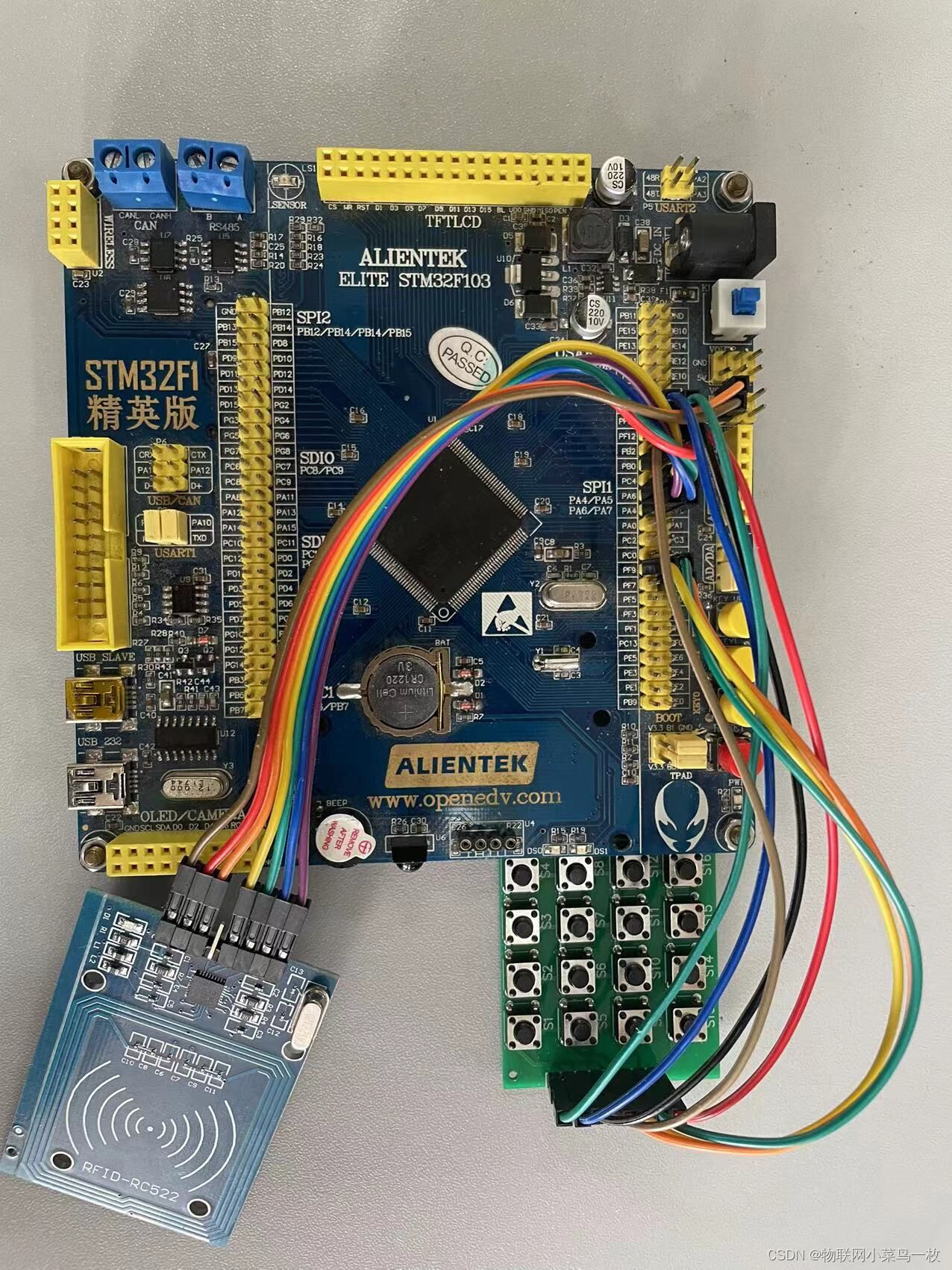
目前所用到的硬件有RC522,STM32和矩阵键盘,实物图如下:
引脚连接以及相关接口设计
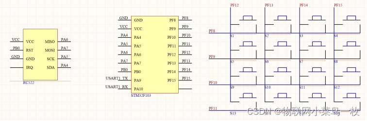
RC522相关的引脚在我上一篇博客已经说过,请大家点开本博客开头的链接查看,4x4的矩阵键盘相关行我们用到的引脚是PF8,9,10,11,相关列用到的引脚是PF12,13,14,15。
按键相关代码如下:
按键初始化函数
void Matrix_ssKey_Pin_Init(void)
{
	GPIO_InitTypeDef GPIO_InitStructure;

	RCC_APB2PeriphClockCmd(RCC_APB2Periph_GPIOF,ENABLE);

	GPIO_InitStructure.GPIO_Mode = GPIO_Mode_Out_PP;
	GPIO_InitStructure.GPIO_Pin = GPIO_Pin_8 | GPIO_Pin_9 | GPIO_Pin_10 | GPIO_Pin_11;//行按键
	GPIO_InitStructure.GPIO_Speed = GPIO_Speed_50MHz;
	GPIO_Init(GPIOF,&GPIO_InitStructure);


	GPIO_InitStructure.GPIO_Mode = GPIO_Mode_IPU ;
	GPIO_InitStructure.GPIO_Pin =  GPIO_Pin_12 | GPIO_Pin_13 | GPIO_Pin_14 | GPIO_Pin_15;//列按键
	GPIO_Init(GPIOF,&GPIO_InitStructure);
}
按键扫描函数
int Matrix_Key_Scan(void)
{
	u8 temp = 0;
	int key_val = -1;

	GPIO_ResetBits(GPIOF,GPIO_Pin_8|GPIO_Pin_9|GPIO_Pin_10|GPIO_Pin_11);
	delay_us(10);

	temp=(GPIO_ReadInputData(GPIOF) >> 8)&0xff;

	if (temp == 0xf0)
	{
			delay_ms(50);
			GPIO_ResetBits(GPIOF,GPIO_Pin_8|GPIO_Pin_9|GPIO_Pin_10|GPIO_Pin_11);
			delay_us(10);
			temp=(GPIO_ReadInputData(GPIOF) >> 8)&0xff;

			if (temp != 0xf0)
			{
				GPIO_Write(GPIOF,0);
				delay_ms(5);
				GPIO_Write(GPIOF,(uint16_t)(0xFE << 8));

				if(((GPIO_ReadInputData(GPIOF) >> 8) & 0XF0) != 0XF0)
				{
						delay_ms(20);

						if(((GPIO_ReadInputData(GPIOF) >> 8) & 0XF0) != 0XF0)
						{
								temp=((GPIO_ReadInputData(GP
最低0.47元/天 解锁文章


 978
978


 被折叠的 条评论
为什么被折叠?
被折叠的 条评论
为什么被折叠?
 到【灌水乐园】发言


