


目录
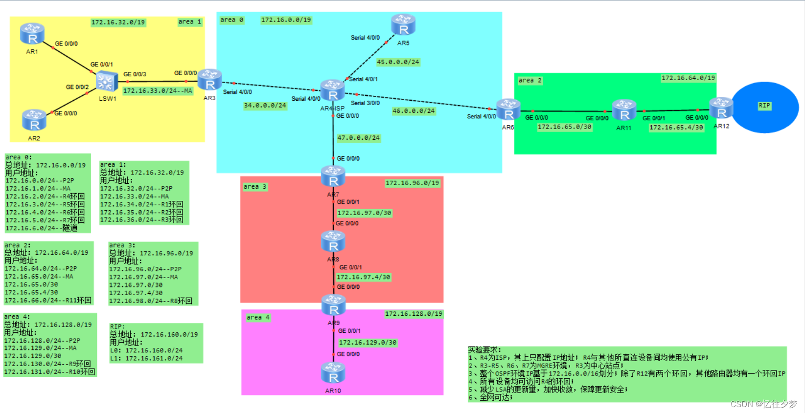
实验要求
1、R4为ISP,其上只配置IP地址;R4与其他所直连设备间均使用公有IP;
2、R3-R5、R6、R7为MGRE环境,R3为中心站点;
3、整个OSPF环境IP基于172.16.0.0/16划分;除了R12有两个环回,其他路由器均有一个环回IP
4、所有设备均可访问R4的环回;
5、减少LSA的更新量,加快收敛,保障更新安全;
6、全网可达;
配置IP
R1:
<Huawei>sys
Enter system view, return user view with Ctrl+Z.
[Huawei]sysname R1
[R1]int g0/0/0
[R1-GigabitEthernet0/0/0]ip add 172.16.33.1 24
[R1-GigabitEthernet0/0/0]
Apr 16 2024 16:02:00-08:00 R1 %%01IFNET/4/LINK_STATE(l)[0]:The line protocol IP
on the interface GigabitEthernet0/0/0 has entered the UP state.
[R1-GigabitEthernet0/0/0]q
[R1]int l0
[R1-LoopBack0]ip add 172.16.34.1 24
[R1]dis ip int b
*down: administratively down
^down: standby
(l): loopback
(s): spoofing
The number of interface that is UP in Physical is 3
The number of interface that is DOWN in Physical is 2
The number of interface that is UP in Protocol is 3
The number of interface that is DOWN in Protocol is 2

Interface                         IP Address/Mask      Physical   Protocol
GigabitEthernet0/0/0              172.16.33.1/24       up         up
GigabitEthernet0/0/1              unassigned           down       down
GigabitEthernet0/0/2              unassigned           down       down
LoopBack0                         172.16.34.1/24       up         up(s)
NULL0                             unassigned           up         up(s)
[R1]
R2:
<Huawei>sys
Enter system view, return user view with Ctrl+Z.
[Huawei]sysname R2
[R2]int g 0/0/0
[R2-GigabitEthernet0/0/0]ip add 172.16.33.2 24
Apr 16 2024 16:09:19-08:00 R2 %%01IFNET/4/LINK_STATE(l)[0]:The line protocol IP
on the interface GigabitEthernet0/0/0 has entered the UP state.
[R2-GigabitEthernet0/0/0]q
[R2]int l0
[R2-LoopBack0]ip add 172.16.35.2 24
[R2-LoopBack0]q
[R2]dis ip int b
*down: administratively down
^down: standby
(l): loopback
(s): spoofing
The number of interface that is UP in Physical is 3
The number of interface that is DOWN in Physical is 2
The number of interface that is UP in Protocol is 3
The number of interface that is DOWN in Protocol is 2

Interface                         IP Address/Mask      Physical   Protocol
GigabitEthernet0/0/0              172.16.33.2/24       up         up
GigabitEthernet0/0/1              unassigned           down       down
GigabitEthernet0/0/2              unassigned           down       down
LoopBack0                         172.16.35.2/24       up         up(s)
NULL0                             unassigned           up         up(s)
[R2]
R3:
<Huawei>sys
Enter system view, return user view with Ctrl+Z.
[Huawei]sysname R3
[R3]int g 0/0/0
[R3-GigabitEthernet0/0/0]ip add 172.16.33.3 24
Apr 16 2024 16:19:20-08:00 R3 %%01IFNET/4/LINK_STATE(l)[0]:The line protocol IP
on the interface GigabitEthernet0/0/0 has entered the UP state.
[R3-GigabitEthernet0/0/0]q
[R3]int s4/0/0
[R3-Serial4/0/0]ip add 34.0.0.3 24
[R3-Serial4/0/0]q
[R3]int l0
[R3-LoopBack0]ip add 172.16.36.3 24
[R3-LoopBack0]
[R3-LoopBack0]q
[R3]dis ip int b
*down: administratively down
^down: standby
(l): loopback
(s): spoofing
The number of interface that is UP in Physical is 4
The number of interface that is DOWN in Physical is 3
The number of interface that is UP in Protocol is 4
The number of interface that is DOWN in Protocol is 3

Interface                         IP Address/Mask      Physical   Protocol
GigabitEthernet0/0/0              172.16.33.3/24       up         up
GigabitEthernet0/0/1              unassigned           down       down
GigabitEthernet0/0/2              unassigned           down       down
LoopBack0                         172.16.36.3/24       up         up(s)
NULL0                             unassigned           up         up(s)
Serial4/0/0                       34.0.0.3/24          up         up
Serial4/0/1                       unassigned           down       down
[R3]
R4:
<Huawei>sys
Enter system view, return user view with Ctrl+Z.
[Huawei]sysname ISP
[ISP]int s4/0/0
[ISP-Serial4/0/0]ip add 34.0.0.4 24
[ISP-Serial4/0/0]
Apr 16 2024 16:23:18-08:00 ISP %%01IFNET/4/LINK_STATE(l)[0]:The line protocol PP
P IPCP on the interface Serial4/0/0 has entered the UP state.
[ISP-Serial4/0/0]q
[ISP]int s4/0/1
[ISP-Serial4/0/1]ip add 45.0.0.4 24
[ISP-Serial4/0/1]
[ISP-Serial4/0/1]q
[ISP]int s3/0/0
[ISP-Serial3/0/0]ip add 46.0.0.4 24
[ISP-Serial3/0/0]q
[ISP]int g 0/0/0
[ISP-GigabitEthernet0/0/0]ip add 47.0.0.4 24
Apr 16 2024 16:24:19-08:00 ISP %%01IFNET/4/LINK_STATE(l)[1]:The line protocol IP
 on the interface GigabitEthernet0/0/0 has entered the UP state.
[ISP-GigabitEthernet0/0/0]q
[ISP]int l0
[ISP-LoopBack0]ip add 172.16.2.4 24
[ISP-LoopBack0]q
[ISP]dis ip int b
*down: administratively down
^down: standby
(l): loopback
(s): spoofing
The number of interface that is UP in Physical is 6
The number of interface that is DOWN in Physical is 3
The number of interface that is UP in Protocol is 6
The number of interface that is DOWN in Protocol is 3

Interface                         IP Address/Mask      Physical   Protocol
GigabitEthernet0/0/0              47.0.0.4/24          up         up
GigabitEthernet0/0/1              unassigned           down       down
GigabitEthernet0/0/2              unassigned           down       down
LoopBack0                         172.16.2.4/24        up         up(s)
NULL0                             unassigned           up         up(s)
Serial3/0/0                       46.0.0.4/24          up         up
Serial3/0/1                       unassigned           down       down
Serial4/0/0                       34.0.0.4/24          up         up
Serial4/0/1                       45.0.0.4/24          up         up
[ISP]
R5:
<Huawei>sys
Enter system view, return user view with Ctrl+Z.
[Huawei]sysname R5
[R5]int s4/0/0
[R5-Serial4/0/0]ip add 45.0.0.5 24
[R5-Serial4/0/0]
Apr 16 2024 16:28:30-08:00 R5 %%01IFNET/4/LINK_STATE(l)[0]:The line protocol PPP
 IPCP on the interface Serial4/0/0 has entered the UP state.
[R5-Serial4/0/0]q
[R5]int l0
[R5-LoopBack0]ip add 172.16.3.5 24
[R5-LoopBack0]q
[R5]dis ip int b
*down: administratively down
^down: standby
(l): loopback
(s): spoofing
The number of interface that is UP in Physical is 3
The number of interface that is DOWN in Physical is 4
The number of interface that is UP in Protocol is 3
The number of interface that is DOWN in Protocol is 4

Interface                         IP Address/Mask      Physical   Protocol
GigabitEthernet0/0/0              unassigned           down       down
GigabitEthernet0/0/1              unassigned           down       down
GigabitEthernet0/0/2              unassigned           down       down
LoopBack0                         172.16.3.5/24        up         up(s)
NULL0                             unassigned           up         up(s)
Serial4/0/0                       45.0.0.5/24          up         up
Serial4/0/1                       unassigned           down       down
[R5]
R6:
<Huawei>sys
Enter system view, return user view with Ctrl+Z.
[Huawei]sysname R6
[R6]int s4/0/0
[R6-Serial4/0/0]ip add 46.0.0.6 24
[R6-Serial4/0/0]
Apr 16 2024 16:31:38-08:00 R6 %%01IFNET/4/LINK_STATE(l)[0]:The line protocol PPP
 IPCP on the interface Serial4/0/0 has entered the UP state.
[R6-Serial4/0/0]q
[R6]int g 0/0/0
[R6-GigabitEthernet0/0/0]ip add 172.16.65.1 30
Apr 16 2024 16:32:10-08:00 R6 %%01IFNET/4/LINK_STATE(l)[1]:The line protocol IP
on the interface GigabitEthernet0/0/0 has entered the UP state.
[R6-GigabitEthernet0/0/0]q
[R6]int l0
[R6-LoopBack0]ip add 172.16.4.6 24
[R6-LoopBack0]
[R6-LoopBack0]q
[R6]dis ip int b
*down: administratively down
^down: standby
(l): loopback
(s): spoofing
The number of interface that is UP in Physical is 4
The number of interface that is DOWN in Physical is 3
The number of interface that is UP in Protocol is 4
The number of interface that is DOWN in Protocol is 3

Interface                         IP Address/Mask      Physical   Protocol
GigabitEthernet0/0/0              172.16.65.1/30       up         up
GigabitEthernet0/0/1              unassigned           down       down
GigabitEthernet0/0/2              unassigned           down       down
LoopBack0                         172.16.4.6/24        up         up(s)
NULL0                             unassigned           up         up(s)
Serial4/0/0                       46.0.0.6/24          up         up
Serial4/0/1                       unassigned           down       down
[R6]
R7:
<Huawei>sys
Enter system view, return user view with Ctrl+Z.
[Huawei]sysname R7
[R7]int g0/0/0
[R7-GigabitEthernet0/0/0]ip add 47.0.0.7 24
[R7-GigabitEthernet0/0/0]
Apr 16 2024 16:34:41-08:00 R7 %%01IFNET/4/LINK_STATE(l)[0]:The line protocol IP
on the interface GigabitEthernet0/0/0 has entered the UP state.
[R7-GigabitEthernet0/0/0]q
[R7]int g0/0/1
[R7-GigabitEthernet0/0/1]ip add 172.16.97.1 30
Apr 16 2024 16:36:46-08:00 R7 %%01IFNET/4/LINK_STATE(l)[1]:The line protocol IP
on the interface GigabitEthernet0/0/1 has entered the UP state.
[R7-GigabitEthernet0/0/1]q
[R7]int l0
[R7-LoopBack0]ip add 172.16.5.7 24
[R7-LoopBack0]q
[R7]dis ip int b
*down: administratively down
^down: standby
(l): loopback
(s): spoofing
The number of interface that is UP in Physical is 4
The number of interface that is DOWN in Physical is 1
The number of interface that is UP in Protocol is 4
The number of interface that is DOWN in Protocol is 1

Interface                         IP Address/Mask      Physical   Protocol
GigabitEthernet0/0/0              47.0.0.7/24          up         up
GigabitEthernet0/0/1              172.16.97.1/30       up         up
GigabitEthernet0/0/2              unassigned           down       down
LoopBack0                         172.16.5.7/24        up         up(s)
NULL0                             unassigned           up         up(s)
[R7]
R8:
<Huawei>sys
Enter system view, return user view with Ctrl+Z.
[Huawei]sysname R8
[R8]int g0/0/0
[R8-GigabitEthernet0/0/0]ip add 172.16.97.2 30
[R8-GigabitEthernet0/0/0]
Apr 16 2024 16:38:49-08:00 R8 %%01IFNET/4/LINK_STATE(l)[0]:The line protocol IP
on the interface GigabitEthernet0/0/0 has entered the UP state.
[R8-GigabitEthernet0/0/0]q
[R8]int g 0/0/1
[R8-GigabitEthernet0/0/1]ip add 172.16.97.5 30
Apr 16 2024 16:41:00-08:00 R8 %%01IFNET/4/LINK_STATE(l)[1]:The line protocol IP
on the interface GigabitEthernet0/0/1 has entered the UP state.
[R8-GigabitEthernet0/0/1]q
[R8]int l0
[R8-LoopBack0]ip add 172.16.98.8 24
[R8-LoopBack0]q
[R8]dis ip int b
*down: administratively down
^down: standby
(l): loopback
(s): spoofing
The number of interface that is UP in Physical is 4
The number of interface that is DOWN in Physical is 1
The number of interface that is UP in Protocol is 4
The number of interface that is DOWN in Protocol is 1

Interface                         IP Address/Mask      Physical   Protocol
GigabitEthernet0/0/0              172.16.97.2/30       up         up
GigabitEthernet0/0/1              172.16.97.5/30       up         up
GigabitEthernet0/0/2              unassigned           down       down
LoopBack0                         172.16.98.8/24       up         up(s)
NULL0                             unassigned           up         up(s)
[R8]
R9:
<Huawei>sys
Enter system view, return user view with Ctrl+Z.
[Huawei]sysname R9
[R9]int g0/0/0
[R9-GigabitEthernet0/0/0]ip add 172.16.97.6 30
[R9-GigabitEthernet0/0/0]
Apr 16 2024 16:43:02-08:00 R9 %%01IFNET/4/LINK_STATE(l)[0]:The line protocol IP
on the interface GigabitEthernet0/0/0 has entered the UP state.
[R9-GigabitEthernet0/0/0]q
[R9]int g 0/0/1
[R9-GigabitEthernet0/0/1]ip add 172.16.129.1 30
Apr 16 2024 16:43:17-08:00 R9 %%01IFNET/4/LINK_STATE(l)[1]:The line protocol IP
on the interface GigabitEthernet0/0/1 has entered the UP state.
[R9-GigabitEthernet0/0/1]q
[R9]int l0
[R9-LoopBack0]ip add 172.16.130.9 24
[R9-LoopBack0]q
[R9]dis ip int b
*down: administratively down
^down: standby
(l): loopback
(s): spoofing
The number of interface that is UP in Physical is 4
The number of interface that is DOWN in Physical is 1
The number of interface that is UP in Protocol is 4
The number of interface that is DOWN in Protocol is 1

Interface                         IP Address/Mask      Physical   Protocol
GigabitEthernet0/0/0              172.16.97.6/30       up         up
GigabitEthernet0/0/1              172.16.129.1/30      up         up
GigabitEthernet0/0/2              unassigned           down       down
LoopBack0                         172.16.130.9/24      up         up(s)
NULL0                             unassigned           up         up(s)
[R9]
R10:
<Huawei>sys
Enter system view, return user view with Ctrl+Z.
[Huawei]sysname R10
[R10]int g 0/0/0
[R10-GigabitEthernet0/0/0]ip add 172.16.129.2 30
[R10-GigabitEthernet0/0/0]
Apr 16 2024 16:45:20-08:00 R10 %%01IFNET/4/LINK_STATE(l)[0]:The line protocol IP
 on the interface GigabitEthernet0/0/0 has entered the UP state.
[R10-GigabitEthernet0/0/0]q
[R10]int l0
[R10-LoopBack0]ip add 172.16.131.10 24
[R10-LoopBack0]q
[R10]dis ip int b
*down: administratively down
^down: standby
(l): loopback
(s): spoofing
The number of interface that is UP in Physical is 3
The number of interface that is DOWN in Physical is 2
The number of interface that is UP in Protocol is 3
The number of interface that is DOWN in Protocol is 2

Interface                         IP Address/Mask      Physical   Protocol
GigabitEthernet0/0/0              172.16.129.2/30      up         up
GigabitEthernet0/0/1              unassigned           down       down
GigabitEthernet0/0/2              unassigned           down       down
LoopBack0                         172.16.131.10/24     up         up(s)
NULL0                             unassigned           up         up(s)
[R10]
R11:
<Huawei>sys
Enter system view, return user view with Ctrl+Z.
[Huawei]sysname R11
[R11]int g0/0/0
[R11-GigabitEthernet0/0/0]ip add 172.16.65.2 30
Apr 16 2024 16:47:02-08:00 R11 %%01IFNET/4/LINK_STATE(l)[0]:The line protocol IP
 on the interface GigabitEthernet0/0/0 has entered the UP state.
[R11-GigabitEthernet0/0/0]q
[R11]int g 0/0/1
[R11-GigabitEthernet0/0/1]ip add 172.16.65.5 30
Apr 16 2024 16:47:26-08:00 R11 %%01IFNET/4/LINK_STATE(l)[1]:The line protocol IP
 on the interface GigabitEthernet0/0/1 has entered the UP state.
[R11-GigabitEthernet0/0/1]q
[R11]int l0
[R11-LoopBack0]ip add 172.16.66.11 24
[R11-LoopBack0]q
[R11]dis ip int b
*down: administratively down
^down: standby
(l): loopback
(s): spoofing
The number of interface that is UP in Physical is 4
The number of interface that is DOWN in Physical is 1
The number of interface that is UP in Protocol is 4
The number of interface that is DOWN in Protocol is 1

Interface                         IP Address/Mask      Physical   Protocol
GigabitEthernet0/0/0              172.16.65.2/30       up         up
GigabitEthernet0/0/1              172.16.65.5/30       up         up
GigabitEthernet0/0/2              unassigned           down       down
LoopBack0                         172.16.66.11/24      up         up(s)
NULL0                             unassigned           up         up(s)
[R11]
R12:
<Huawei>sys
Enter system view, return user view with Ctrl+Z.
[Huawei]sysname R12
[R12]int g 0/0/0
[R12-GigabitEthernet0/0/0]ip add 172.16.65.6 30
[R12-GigabitEthernet0/0/0]
Apr 16 2024 19:09:06-08:00 R12 %%01IFNET/4/LINK_STATE(l)[0]:The line protocol IP
 on the interface GigabitEthernet0/0/0 has entered the UP state.
[R12-GigabitEthernet0/0/0]q
[R12]int l0
[R12-LoopBack0]ip add 172.16.160.12 24
[R12-LoopBack0]q
[R12]int l1
[R12-LoopBack1]ip add 172.16.161.12 24
[R12-LoopBack1]
[R12-LoopBack1]q
[R12]dis ip int b
*down: administratively down
^down: standby
(l): loopback
(s): spoofing
The number of interface that is UP in Physical is 4
The number of interface that is DOWN in Physical is 2
The number of interface that is UP in Protocol is 4
The number of interface that is DOWN in Protocol is 2

Interface                         IP Address/Mask      Physical   Protocol
GigabitEthernet0/0/0              172.16.65.6/30       up         up
GigabitEthernet0/0/1              unassigned           down       down
GigabitEthernet0/0/2              unassigned           down       down
LoopBack0                         172.16.160.12/24     up         up(s)
LoopBack1                         172.16.161.12/24     up         up(s)
NULL0                             unassigned           up         up(s)
[R12]
构建外部RIP协议用户组
R12:
[R12]rip 1
[R12-rip-1]v 2
[R12-rip-1]undo summary
[R12-rip-1]net 172.16.0.0
配置公网通
手动配置通向公网的缺省路由:
R3:
[R3]ip route-static 0.0.0.0 0 34.0.0.4R5:
[R5]ip route-static 0.0.0.0 0 45.0.0.4R6:
[R6]ip route-static 0.0.0.0 0 46.0.0.4R7:
[R7]ip route-static 0.0.0.0 0 47.0.0.4构建MGRE隧道
创建隧道
R3:
[R3]int Tunnel 0/0/0
[R3-Tunnel0/0/0]ip add 172.16.6.3 24
[R3-Tunnel0/0/0]tunnel-protocol gre p2mp
[R3-Tunnel0/0/0]source 34.0.0.3
R5:
[R5]int Tunnel 0/0/0
[R5-Tunnel0/0/0]ip add 172.16.6.5 24
[R5-Tunnel0/0/0]tunnel-protocol gre p2mp
[R5-Tunnel0/0/0]source Serial 4/0/0
R6:
[R6]int Tunnel 0/0/0
[R6-Tunnel0/0/0]ip add 172.16.6.6 24
[R6-Tunnel0/0/0]tunnel-protocol gre p2mp
[R6-Tunnel0/0/0]source Serial 4/0/0
R7:
[R7]int Tunnel 0/0/0
[R7-Tunnel0/0/0]ip add 172.16.6.7 24
[R7-Tunnel0/0/0]tunnel-protocol gre p2mp
[R7-Tunnel0/0/0]source GigabitEthernet 0/0/0
配置下一跳解析协议(NHRP)
中心站点R3:
[R3]int t0/0/0
[R3-Tunnel0/0/0]nhrp network-id 100
[R3-Tunnel0/0/0]nhrp entry multicast dynamic//开启伪广播
R5:
[R5]int t0/0/0
[R5-Tunnel0/0/0]nhrp network-id 100
[R5-Tunnel0/0/0]nhrp entry 172.16.6.3 34.0.0.3 register //找中心站点注册信息
R6:
[R6]int t0/0/0
[R6-Tunnel0/0/0]nhrp network-id 100
[R6-Tunnel0/0/0]nhrp entry 172.16.6.3 34.0.0.3 register
R7:
[R7]int t0/0/0
[R7-Tunnel0/0/0]nhrp network-id 100
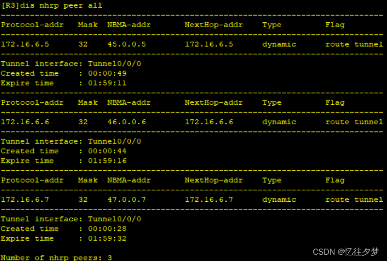
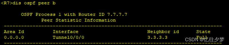
[R7-Tunnel0/0/0]nhrp entry 172.16.6.3 34.0.0.3 register 查看建邻情况:
R3:
OSPF私网通
area 0(公网区域不宣告):
R3:
[R3]ospf 1
[R3-ospf-1]a 0
[R3-ospf-1-area-0.0.0.0]net 172.16.6.0 0.0.0.255
R5:
[R5]ospf 1 router-id 5.5.5.5
[R5-ospf-1]area 0
[R5-ospf-1-area-0.0.0.0]net 172.16.3.0 0.0.0.255
[R5-ospf-1-area-0.0.0.0]network 172.16.6.0 0.0.0.255
R6:
[R6]ospf 1 router-id 6.6.6.6
[R6-ospf-1]area 0
[R6-ospf-1-area-0.0.0.0]net 172.16.4.0 0.0.0.255
[R6-ospf-1-area-0.0.0.0]net 172.16.6.0 0.0.0.255
R7:
[R7]ospf 1 router-id 7.7.7.7
[R7-ospf-1]area 0
[R7-ospf-1-area-0.0.0.0]net 172.16.5.0 0.0.0.255
[R7-ospf-1-area-0.0.0.0]net 172.16.6.0 0.0.0.255
因为Tunnel口默认为点对点类型,故需要修改 Tunnel口接口类型才能实现每一个路由器建立连接:
R3:
[R3]int t0/0/0
[R3-Tunnel0/0/0]ospf network-type broadcast
R5:
[R5]int t0/0/0
[R5-Tunnel0/0/0]ospf network-type broadcast
R6:
[R6]int t0/0/0
[R6-Tunnel0/0/0]ospf network-type broadcast
R7:
[R7]int t0/0/0
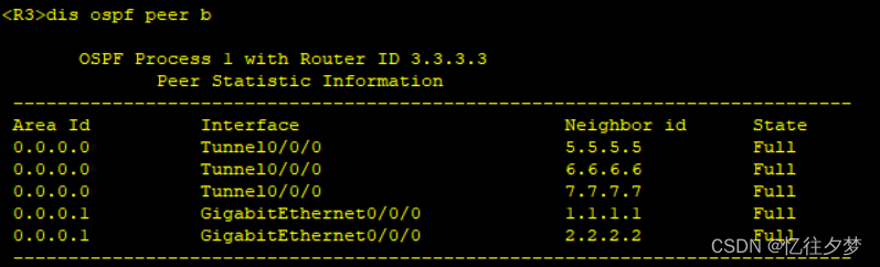
[R7-Tunnel0/0/0]ospf network-type broadcast 查看区域0邻居情况:
R3:
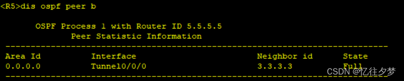
R5:
R6:

R7:
area 1:
R1:
[R1]ospf 1 router-id 1.1.1.1
[R1-ospf-1]area 1
[R1-ospf-1-area-0.0.0.1]network 172.16.33.0 0.0.0.255
[R1-ospf-1-area-0.0.0.1]network 172.16.34.0 0.0.0.255
R2:
[R2]ospf 1 router-id 2.2.2.2
[R2-ospf-1]area 1
[R2-ospf-1-area-0.0.0.1]net 172.16.33.0 0.0.0.255
[R2-ospf-1-area-0.0.0.1]net 172.16.35.0 0.0.0.255
R3:
[R3]ospf 1 router-id 3.3.3.3
[R3-ospf-1]area 1
[R3-ospf-1-area-0.0.0.1]net 172.16.33.0 0.0.0.255
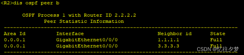
[R3-ospf-1-area-0.0.0.1]net 172.16.36.0 0.0.0.255查看区域1邻居表:
R2:
R1:

area 2:
R6:
[R6]ospf 1
[R6-ospf-1]a 2
[R6-ospf-1-area-0.0.0.2]net 172.16.65.1 0.0.0.0//精确宣告
R11:
R11]ospf 1 router-id 11.11.11.11
[R11-ospf-1]a 2
[R11-ospf-1-area-0.0.0.2]net 172.16.65.2 0.0.0.0
[R11-ospf-1-area-0.0.0.2]net 172.16.66.0 0.0.0.255
[R11-ospf-1-area-0.0.0.2]net 172.16.65.5 0.0.0.0
R12:
[R12]ospf 1 router-id 12.12.12.12
[R12-ospf-1]a 2
[R12-ospf-1-area-0.0.0.2]net 172.16.65.6 0.0.0.0
引入RIP区域的路由:
R12:
[R12-ospf-1-area-0.0.0.2]q
[R12-ospf-1]im
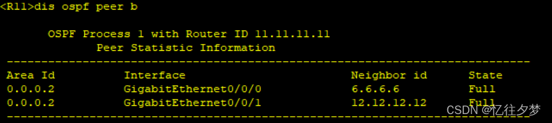
[R12-ospf-1]import-route rip查看邻居表:
R6:

R11:
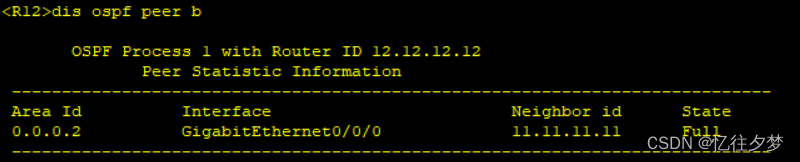
R12:
area 3:
R7:
[R7]ospf 1
[R7-ospf-1]a 3
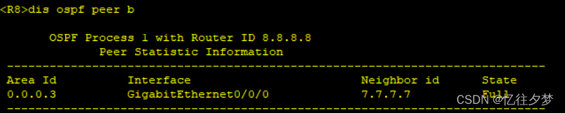
[R7-ospf-1-area-0.0.0.3]net 172.16.97.1 0.0.0.0//精确宣告R8:
[R8]ospf 1 router-id 8.8.8.8
[R8-ospf-1]a 3
[R8-ospf-1-area-0.0.0.3]net 172.16.97.2 0.0.0.0
[R8-ospf-1-area-0.0.0.3]net 172.16.97.5 0.0.0.0
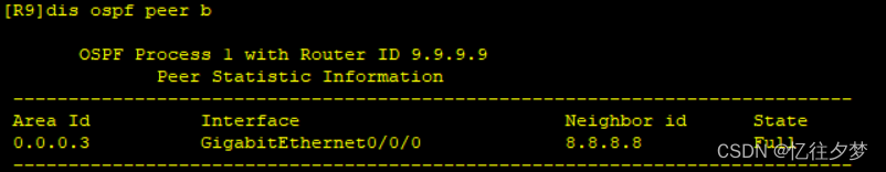
[R8-ospf-1-area-0.0.0.3]net 172.16.98.0 0.0.0.255R9:
[R9]ospf 1 router-id 9.9.9.9
[R9-ospf-1]a 3
[R9-ospf-1-area-0.0.0.3]net 172.16.97.6 0.0.0.0
查看邻居表:
R7:

R8:
R9:
area 4:
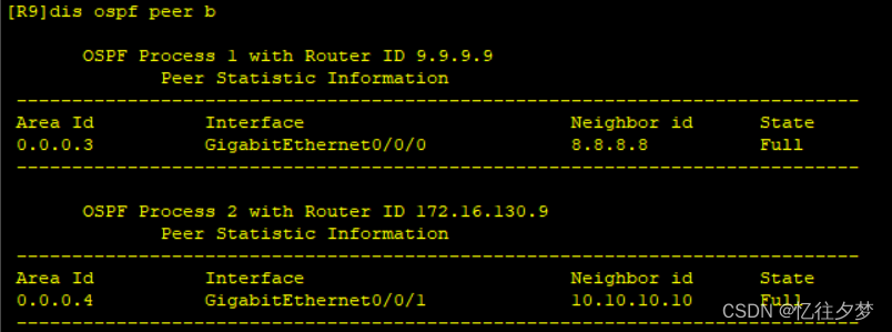
由于area 4被area 3与area 0隔开,故这里将使用新建一个ospf进程重发布:
R9:
[R9]ospf 2
[R9-ospf-2]a 4
[R9-ospf-2-area-0.0.0.4]net 172.16.129.1 0.0.0.0
[R9-ospf-2-area-0.0.0.4]net 172.16.130.0 0.0.0.255
[R9-ospf-2-area-0.0.0.4]q
[R9-ospf-2]import-route ospf 1
[R9-ospf-2]q
[R9]ospf 1
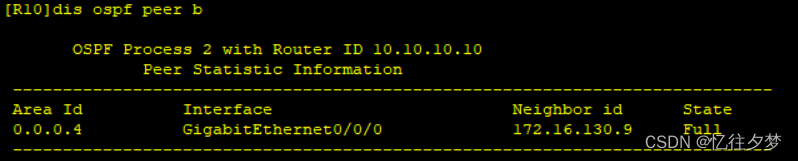
[R9-ospf-1]import-route ospf 2R10:
[R10]ospf 2 router-id 10.10.10.10
[R10-ospf-2]a 4
[R10-ospf-2-area-0.0.0.4]net 172.16.131.0 0.0.0.255
[R10-ospf-2-area-0.0.0.4]net 172.16.129.2 0.0.0.0
查看邻居表:
R9:
R10:
取消R5,R6,R7的选举权利
利于更快选举DR:
R5:
[R5]int t0/0/0
[R5-Tunnel0/0/0]ospf dr-priority 0
R6:
[R6]int t0/0/0
[R6-Tunnel0/0/0]ospf dr-priority 0
R7:
[R7]int t0/0/0
[R7-Tunnel0/0/0]ospf dr-priority 0
检测网络:
R10pingR1环回:
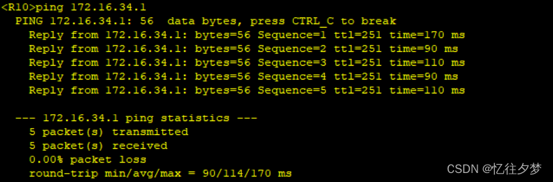
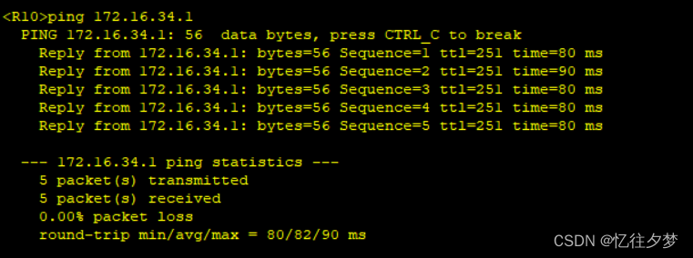
R10pingR1:
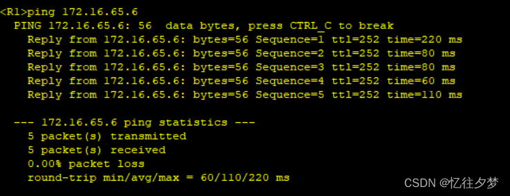
R1pingR12:
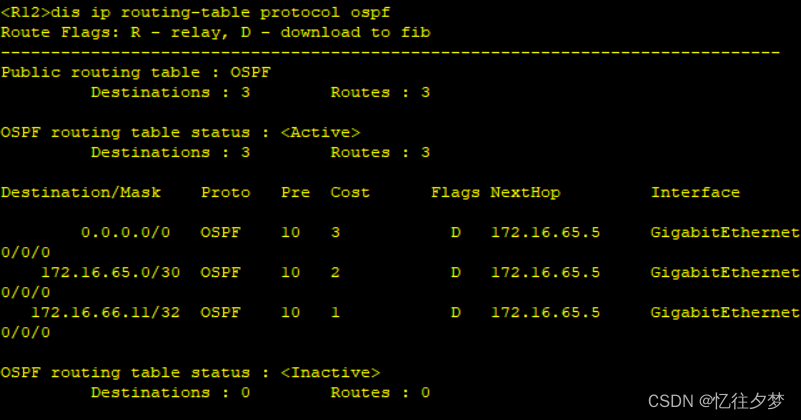
通过观察路由表已经基本可以看出私网可达了。
配置easy IP
R3:
[R3]acl 2000
[R3-acl-basic-2000]rule permit source 172.16.0.0 0.0.255.255
[R3-acl-basic-2000]q
[R3]int s4/0/0
[R3-Serial4/0/0]nat outbound 2000
R6:
[R6]acl 2000
[R6-acl-basic-2000]rule permit source 172.16.0.0 0.0.255.255
[R6-acl-basic-2000]q
[R6]int s4/0/0
[R6-Serial4/0/0]nat outbound 2000
R7:
[R7]acl 2000
[R7-acl-basic-2000]rule permit source 172.16.0.0 0.0.255.255
[R7-acl-basic-2000]q
[R7]int g0/0/0
[R7-GigabitEthernet0/0/0]nat outbound 2000
因为用户路由器没有通向ISP的路由条目,所以ping不同,故我们需要在ospf中手动下发一条缺省,以此达到全网通的需求。这里不使用手动下发,直接使用特殊区域的自动下发的特性,既可以简化路由条目,也可以实现全网通的需求。
配置特殊区域
这里需要尽可能的减少路由条目,故我们选用totally stub区域和totally NSSA区域来让路由条目达到最简状态,也可以使用路由聚合(精简的是area 0的路由条目)的方法减少路由条目,但因为rip宣告时包括了一个大的网段,而ospf选路比rip的优先级高,故area 2中R11-R12的网段不能被聚合,会多出来一个网段出现在聚合网段后的路由表里。
area 1:
R1:
[R1]ospf 1
[R1-ospf-1]a 1
[R1-ospf-1-area-0.0.0.1]stub no-summary
R2:
[R2]ospf 1
[R2-ospf-1]a 1
[R2-ospf-1-area-0.0.0.1]stub no-summary
R3:
[R3]ospf 1
[R3-ospf-1]a 1
[R3-ospf-1-area-0.0.0.1]stub no-summary
area 2:
R6:
[R6]ospf 1
[R6-ospf-1]a 2
[R6-ospf-1-area-0.0.0.2]nssa no-summary
R11:
[R11]ospf 1
[R11-ospf-1]a 2
[R11-ospf-1-area-0.0.0.2]nssa no-summary
R12:
[R12]ospf 1
[R12-ospf-1]a 2
[R12-ospf-1-area-0.0.0.2]nssa no-summary
area 3:
R7:
[R7]ospf 1
[R7-ospf-1]a 3
[R7-ospf-1-area-0.0.0.3]nssa no-summary
R8:
[R8]ospf 1
[R8-ospf-1]a 3
[R8-ospf-1-area-0.0.0.3]nssa no-summary
R9:
[R9]ospf 1
[R9-ospf-1]a 3
[R9-ospf-1-area-0.0.0.3]nssa no-summary
area 4:
由于在area 3成为otally NSSA区域后area 4被当作域外而无法默认下发缺省路由,所以需要向area 4的设备手动下发一条缺省路由。
因为R9上有一条R7下发的缺省所以不用在命令中写"always":
[R9]ospf 2
[R9-ospf-2]default-route-advertise
检测
随机查看几个路由器的ospf路由表:
R1:

R10:

R12:
 R8:
R8:
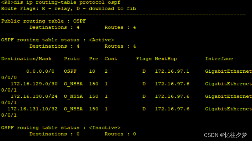
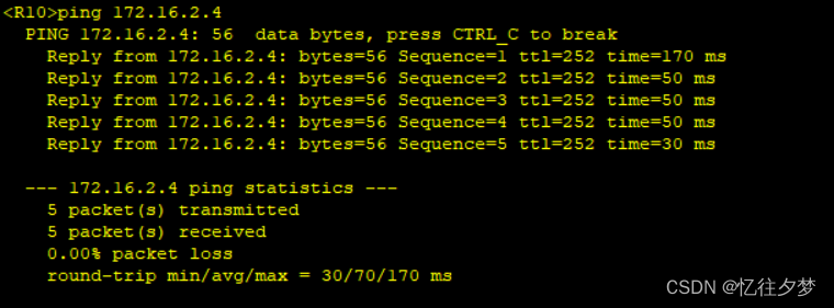
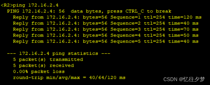
看看随机私有网络路由器能否ping通ISP的环回:
R10:
R2:
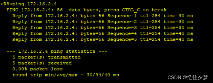
R8:

R11:
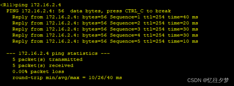
由此,全网可达。
加快收敛速度
通过更改hello时间来解决(修改的速度尽快):
在每一个需要建立邻居关系的接口下配置:
ospf timer hello 5若两个接口hello时间不同,将不能建立邻接关系。
修改hello时间为5秒。达到加快收敛的作用。
保障安全
使用ospf的区域认证:
area 0:
R3:
[R3]ospf 1
[R3-ospf-1]a 0
[R3-ospf-1-area-0.0.0.0]authentication-mode md5 1 cipher 123456
R5:
[R5]ospf 1
[R5-ospf-1]a 0
[R5-ospf-1-area-0.0.0.0]authentication-mode md5 1 cipher 123456
R6:
[R6]ospf 1
[R6-ospf-1]a 0
[R6-ospf-1-area-0.0.0.0]authentication-mode md5 1 cipher 123456
R7:
[R7]ospf 1
[R7-ospf-1]a 0
[R7-ospf-1-area-0.0.0.0]authentication-mode md5 1 cipher 123456
area 1:
R1:
[R1]ospf 1
[R1-ospf-1]a 1
[R1-ospf-1-area-0.0.0.1]authentication-mode md5 1 cipher a1234
R2:
[R2]ospf 1
[R2-ospf-1]a 1
[R2-ospf-1-area-0.0.0.1]authentication-mode md5 1 cipher a1234
R3:
[R3]ospf 1
[R3-ospf-1]a 1
[R3-ospf-1-area-0.0.0.1]authentication-mode md5 1 cipher a1234
area 2:
R6:
[R6]ospf 1
[R6-ospf-1]a 2
[R6-ospf-1-area-0.0.0.2]authentication-mode md5 1 cipher b1234
R11:
[R11]ospf 1
[R11-ospf-1]a 2
[R11-ospf-1-area-0.0.0.2]authentication-mode md5 1 cipher b1234
R12:
[R12]ospf 1
[R12-ospf-1]a 2
[R12-ospf-1-area-0.0.0.2]authentication-mode md5 1 cipher b1234
area 3:
R7:
[R7]ospf 1
[R7-ospf-1]a 3
[R7-ospf-1-area-0.0.0.3]authentication-mode md5 1 cipher c1234
R8:
[R8]ospf 1
[R8-ospf-1]a 3
[R8-ospf-1-area-0.0.0.3]authentication-mode md5 1 cipher c1234
R9:
[R9]ospf 1
[R9-ospf-1]a 3
[R9-ospf-1-area-0.0.0.3]authentication-mode md5 1 cipher c1234
area 4:
R9:
[R9]ospf 2
[R9-ospf-2]a 4
[R9-ospf-2-area-0.0.0.4]authentication-mode md5 1 cipher d1234
R10:
[R10]ospf 2
[R10-ospf-2]a 4
[R10-ospf-2-area-0.0.0.4]authentication-mode md5 1 cipher d1234
检测全网通
R1pingISP环回:

R10pingR12:

R8pingISP环回:
配置完成。


 5333
5333

 被折叠的 条评论
为什么被折叠?
被折叠的 条评论
为什么被折叠?
 到【灌水乐园】发言


