


1、First LED
Through the pcb file of NodeMCU (see Figure-1 or https://github.com/nodemcu/nodemcu-devkit-v1.0/blob/master/NODEMCU_DEVKIT_V1.0.PDF ), we can find the first led which connected by GPIO16 and VDD3V3. The index of pin is 0. (see another article of mine:《The Operation and Map of NodeMCU》). By executing the Code Block-1 can light it.
2、Second LED
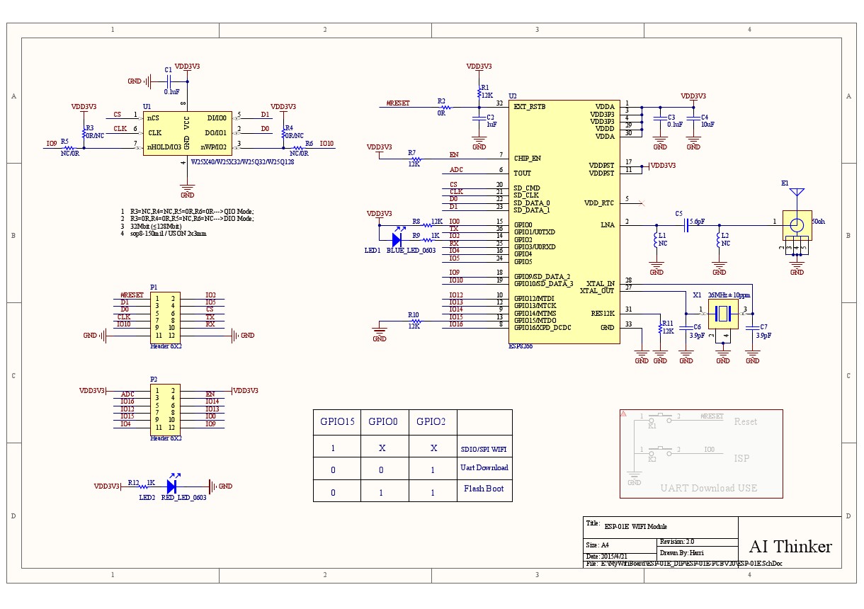
By reading the circuit design schematic of ESP8266(Figure-2), we can see the led connected by GPIO2 and VDD3 ,which's pin index is 4. Executing the Code Block-2 can light it.
—————————————————————————————————————————
上面是练英语写作的,欢迎吐槽 。中文如下:
1、第一个LED
通过NodeMCU的PCB电路图文件 (Figure-1 或者参考官方文档https://github.com/nodemcu/nodemcu-devkit-v1.0/blob/master/NODEMCU_DEVKIT_V1.0.PDF ),我们可以找到第一个LED,两端连接到3.3V电压和GPIO16。对照我的另一篇文章《NodeMCU GPIO操作与引脚映射》可以查到其引脚序号为0。
下图为NodeMCU部分电路原理图Figure-1:
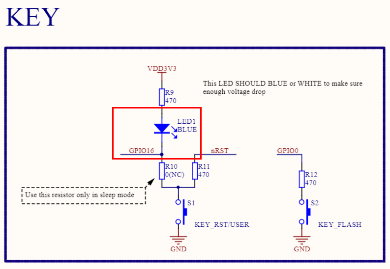
执行下列代码即可点亮它。
Code Block-1:
- gpio.mode(0,gpio.OUTPUT)
- gpio.write(0, gpio.LOW)
熄灭: gpio.write(0, gpio.HIGH)
2、第二个LED
查阅ESP8266的电路原理图可知,LED连接的是3.3V电压和GPIO2,对应引脚序号为4。
下图为ESP8266部分电路原理图Figure-2:

Code Block-2:
- gpio.mode(4,gpio.OUTPUT)
- gpio.write(4, gpio.LOW)
熄灭: gpio.write(4, gpio.HIGH)
【转载请注明出处:http://blog.csdn.net/leytton/article/details/51650082】


 699
699


 被折叠的 条评论
为什么被折叠?
被折叠的 条评论
为什么被折叠?
 到【灌水乐园】发言


