


 本文详细阐述了基于FPGA的Miller编码和解码实现过程。Miller码是一种变形双相码,用于数字通信中。编码部分通过状态机实现,确保在信息码连续时交错编码,解码部分则通过寻找特定码型来恢复原始数据。在解码时,如果失去同步头,则会重新寻找,确保正确解码。整个实现过程涉及到了时钟管理和同步问题。
基于FPGA的密勒(Miller)编解码 实现
一、Miller编码基本原理
上篇文章《曼切斯特编解码实现》,介绍了曼切斯特编解码的实现,本篇介绍Miller编解码的实现。
密勒码(Miller码)也称延迟调制码,是一种变形双相码。其编码规则:对原始符号“1”码元起始不跃变,中心点出现跃变来表示,即用10或01表示。信息码连“1”时,后面的“1”要交错编码;信息码中的“0”编码为双极非归零码“00”或者“11”,即码元中间不跳变;信息码单个“0”时,其前沿、中间时刻、后沿均不跳变;信息码连“0”时,两个“0”码元的间隔跳变。
简单来说由于密勒码是特殊的数字双相码(曼彻斯特编码),即当信息中数据为1的时候就用01或者10表示,当数据为0的时候,就是用00与11进行交替。
Miller码如下图所示
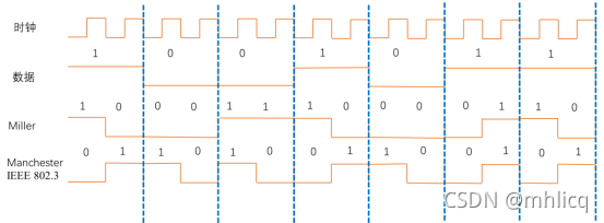
从图中可以看出,Miller码编码后,频率变换相对Manchester码缓慢了许多
二、Miller编码实现
Miller编码模块如下图所示
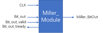
Bit_out:表示要编码的bit数据
Bit_out_valid:表示当前bit数据有效
Bit_out_tready:表示当前bit以完成编码输出
Miller_BitOut:表示Miller编码后输出
module Miller_Module(
 		input   clk,   //32M

        input   Bit_out,
        input   Bit_out_valid,
        output  Bit_out_tready,

        output  Miller_BitOut  //2M
    );

    //reg             Bit_out_tready=0;
    reg             Miller_BitOut=0;
    reg     [7:0]   clk_cnt = 0;

    reg     [2:0]   state_reg = 0;
    reg     [1:0]   send_tmp  = 0;


    reg             Bit_out_valid_r1 = 0;
    reg             Bit_out_valid_r2 = 0;
    wire            Bit_out_valid_posedge = Bit_out_valid_r1 && (~Bit_out_valid_r2);
    always @(posedge clk) begin
        Bit_out_valid_r1<=Bit_out_valid;
        Bit_out_valid_r2<=Bit_out_valid_r1;
    end


    always @ (posedge clk) begin
        case (state_reg)
        0:begin
            if(Bit_out_valid_posedge)
                state_reg<=1;
        end

        1:begin
            if(clk_cnt==32/2-1)   begin//输入时钟32M、曼切斯特速率2M
                clk_cnt<=0;
                if(Bit_out_valid==0)
                    state_reg<=0;
            end
            else
                clk_cnt<=clk_cnt+1;
        end
       endcase
    end
    reg [1:0]    pre_send_tmp  = 0;
    always @ (posedge clk) begin
            if(clk_cnt==15) begin
                if(Bit_out==0 && (pre_send_tmp==2'b00  || pre_send_tmp==2'b01))
                    send_tmp<=2'b11;
                else if(Bit_out==0 && (pre_send_tmp==2'b11 || pre_send_tmp==2'b10))
                    send_tmp<=2'b00;
                else if(Bit_out==1 && (pre_send_tmp==2'b00  || pre_send_tmp==2'b10))
                    send_tmp<=2'b01;
                else if(Bit_out==1 && (pre_send_tmp==2'b11  || pre_send_tmp==2'b01))
                    send_tmp<=2'b10;
             end

             if(clk_cnt==0)
                pre_send_tmp<= send_tmp;
    end

    always @ (posedge clk) begin
        if(state_reg==1)
        begin
            if(clk_cnt==0)
                Miller_BitOut<=send_tmp[1];
            else if(clk_cnt==8)
                Miller_BitOut<=send_tmp[0];
        end
        else
                Miller_BitOut<=0;
    end

    assign   Bit_out_tready = (clk_cnt==13) ? 1'b1 :1'b0;  //提前2个时钟置高
endmodule
三、Miller解码实现
Miller解码模块如下图所示
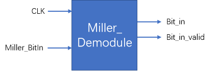
Bit_in:表示解码的bit数据
Bit_in_valid:表示解码的bit数据有效
Miller_BitIn:表示要解码的Miller编码输入
在Miller解码时,首先需要寻找4个连0或连1,即2个码元宽度的00或11,因为4个连0前后都是1,4个连1前后都是0,找到4个连0或连1,就找到了解码的起始,之后就可以正确解出码元。
代码如下
module Miller_Demodule(
 		input   clk,   //32M

        output   Bit_in,
        output   Bit_in_valid,
        input    Miller_BitIn       //2M
    );


    reg             Bit_in  = 0;
    reg             Bit_in_valid  = 0;
    reg     [7:0]   clk_cnt = 0;
    reg             bit_cnt = 0;
    reg     [4:0]   Miller_BitIn_tmp = 0;

    reg             Bit_sync  = 0;

    reg     [2:0]   state_reg = 0;

    reg             Miller_BitIn_r1 = 0;
    wire            Miller_BitIn_posedge = Miller_BitIn && (~Miller_BitIn_r1);

    always @(posedge clk) begin
        Miller_BitIn_r1<=Miller_BitIn;
    end


    always @ (posedge clk) begin
        case (state_reg)
        0:begin
            clk_cnt<=0;
            Bit_sync<=0;
            if(Miller_BitIn_posedge)
                state_reg<=1;
        end

        1:begin
            if(clk_cnt==7)  //输入时钟32M、曼切斯特速率2M
                clk_cnt<=0;
            else
                clk_cnt<=clk_cnt+1;

            if(clk_cnt==7)
            begin
                if((Miller_BitIn_tmp[3:0]==4'b0000 || Miller_BitIn_tmp[3:0]==4'b1111) && Bit_sync==0)//寻找 同步头
                    Bit_sync<=1;
                else
                if((Miller_BitIn_tmp[3:0]==4'b0000 || Miller_BitIn_tmp[3:0]==4'b0010
                    || Miller_BitIn_tmp[3:0]==4'b0100 || Miller_BitIn_tmp[3:0]==4'b0101
                    || Miller_BitIn_tmp[3:0]==4'b1010  || Miller_BitIn_tmp[3:0]==4'b1011
                    || Miller_BitIn_tmp[3:0]==4'b1101  || Miller_BitIn_tmp[3:0]==4'b1111)
                    && bit_cnt==1) //同步头 丢失后 重新寻找头
                begin
                    Bit_sync<=0;
                    state_reg<=0;
                end
                //else if(Miller_BitIn_tmp[4:0] == 5'b00000 || Miller_BitIn_tmp[4:0] == 5'b11111)  //当超过5个0或5个1时,Miller解码结束
                //    state_reg<=0;
            end

        end
       endcase
    end


    always @ (posedge clk) begin
    if(Bit_sync==1)
    begin
        if(clk_cnt==4)
            bit_cnt<=bit_cnt+1;
     end
     else
            bit_cnt<=0;
    end


    always @ (posedge clk) begin
    if(state_reg==1) begin
        if(clk_cnt==4)
            Miller_BitIn_tmp[4:0]<={Miller_BitIn_tmp[3:0],Miller_BitIn};
    end
    else
            Miller_BitIn_tmp[4:0]<=0;
    end

    always @ (posedge clk) begin
        if(clk_cnt==7 && bit_cnt==1) begin
            case(Miller_BitIn_tmp[1:0])
                2'b01,2'b10:Bit_in<=1;
                2'b11,2'b00:Bit_in<=0;
                default:Bit_in<=0;
         endcase
       end
    end

    always @ (posedge clk) begin
        if(bit_cnt==1 && clk_cnt==0 && Bit_sync==1) begin
                Bit_in_valid<=1;
        end
        else
               Bit_in_valid<=0;

    end

endmodule
在上面代码中,当同步头丢失之后,需要重新寻找同步头,使用了如下语句判断同步头是否丢失。
可以思考一下为什么。
				if((Miller_BitIn_tmp[3:0]==4'b0000 || Miller_BitIn_tmp[3:0]==4'b0010
                    || Miller_BitIn_tmp[3:0]==4'b0100 || Miller_BitIn_tmp[3:0]==4'b0101
                    || Miller_BitIn_tmp[3:0]==4'b1010  || Miller_BitIn_tmp[3:0]==4'b1011
                    || Miller_BitIn_tmp[3:0]==4'b1101  || Miller_BitIn_tmp[3:0]==4'b1111)
                    && bit_cnt==1) //同步头 丢失后 重新寻找头
                begin
                    Bit_sync<=0;
                    state_reg<=0;
                end
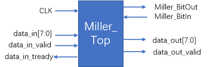
四、Miller编解码实现
Miller编解码顶层模块如下图所示,顶层模块使用AXI-Lite接口。
module Miller_top(
    input   clk,
    input   rst_p,

    input [7:0]   data_in,
    input         data_in_valid,
    output        data_tready,

    output  [7:0] data_out,
    output        data_out_valid,

    input         Miller_BitIn,
    output        Miller_BitOut
    );


    reg         Bit_out  ;         //1bit发送数据
    reg         Bit_out_valid =0 ;//1bit发送数据有效信号
    wire        Bit_out_tready;  //发送1bit结束

    wire        Bit_in  ;        //1bit接收数据
    wire        Bit_in_valid;    //1bit接收数据有效信号

    reg     [7:0]   data_in_reg;
    reg     [7:0]   bit_cnt = 0;
    reg     [2:0]   state_reg = 0;

    reg             data_in_valid_r1 = 0;
    reg             data_in_valid_r2 = 0;
    wire            data_in_valid_posedge = data_in_valid_r1 && (~data_in_valid_r2);


/
    always @(posedge clk) begin
        data_in_valid_r1<=data_in_valid;
        data_in_valid_r2<=data_in_valid_r1;
    end


        always @ (posedge clk) begin
        case (state_reg)
        0:begin
            if(data_in_valid_posedge)
            begin
                Bit_out_valid<=1;
                state_reg<=1;
            end
        end

        1:begin
            if(Bit_out_tready)  begin
                if(bit_cnt==7)   begin
                    bit_cnt<=0;
                    if(data_in_valid==0) begin
                        Bit_out_valid<=0;
                        state_reg<=0;
                    end
                end
                else
                    bit_cnt<=bit_cnt+1;
            end
        end
       endcase
    end

     always @ (posedge clk) begin
        if(bit_cnt==0)
            data_in_reg<=data_in;
     end

     always @ (posedge clk) begin
        case(bit_cnt)
            0:Bit_out<=data_in_reg[7];
            1:Bit_out<=data_in_reg[6];
            2:Bit_out<=data_in_reg[5];
            3:Bit_out<=data_in_reg[4];
            4:Bit_out<=data_in_reg[3];
            5:Bit_out<=data_in_reg[2];
            6:Bit_out<=data_in_reg[1];
            7:Bit_out<=data_in_reg[0];
        endcase
     end

    assign    data_tready  = (bit_cnt==7)   ?  1: 0;

///Miller 编码//


    Miller_Module Miller_tx(
        .clk(clk),
        .Bit_out(Bit_out),
        .Bit_out_valid(Bit_out_valid),
        .Bit_out_tready(Bit_out_tready),
        .Miller_BitOut(Miller_BitOut)
    );

 ///Miller 解码//
   Miller_Demodule Miller_rx(
        .clk(clk),
        .Bit_in(Bit_in),
        .Bit_in_valid(Bit_in_valid),

        .Miller_BitIn(Miller_BitOut)//Mqst_BitIn
    );


endmodule
仿真代码如下所示,与上篇Manchester编解码代码一样
module test_miller(

    );

     reg   clk;
    reg   rst_p;

    reg [7:0]   data_in = 0;
    reg         data_in_valid;
    wire        data_tready;

    wire  [7:0] data_out;
    wire        data_out_valid;

    reg         Miller_BitIn;
    wire        Miller_BitOut;

        Miller_top Miller_top(
        .clk(clk),
        .rst_p(rst_p),
        .data_in(data_in),
        .data_in_valid(data_in_valid),
        .data_tready(data_tready) ,
        .data_out(data_out),
        .data_out_valid(data_out_valid),
        .Miller_BitIn(Miller_BitIn) ,
        .Miller_BitOut(Miller_BitOut)

    );

    initial   begin
        #0
        clk = 0;
        rst_p =1;
        data_in_valid = 0;
        #100

        rst_p = 0;
        data_in_valid = 1;

    end

    always #15 clk =~clk;

    always @ (posedge data_tready) begin
        if(data_in==11)
        begin
            data_in<=0;
            data_in_valid<=0;
        end
        else
            data_in<=data_in+1;
     end

endmodule
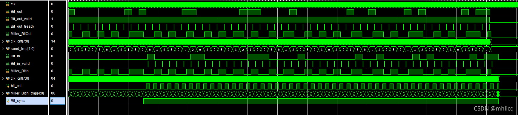
仿真结果如下图所示


 1万+
1万+

 被折叠的 条评论
为什么被折叠?
被折叠的 条评论
为什么被折叠?
 到【灌水乐园】发言


