


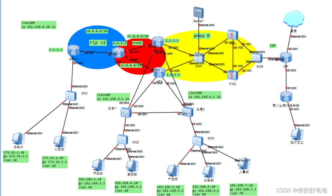
交换机、路由器防火墙配置
VLAN及VLAN间路由
首先配置两个三层交换机作为内网通信使用的三层交换机LSW1、2
创建VLAN
三层交换机与下面的二层交换机连接设置trunk
三层交换机与路由器连接设置access
三层1:
vlan batch 30 40 50 60 70 100
interface Vlanif30
ip address 192.168.3.1 255.255.255.0
interface Vlanif40
ip address 192.168.4.1 255.255.255.0
interface Vlanif50
ip address 192.168.5.1 255.255.255.0
interface Vlanif60
ip address 192.168.6.1 255.255.255.0
interface Vlanif70
ip address 192.168.7.1 255.255.255.0
interface Vlanif100
ip address 192.168.8.11 255.255.255.0
interface GigabitEthernet0/0/1
port link-type trunk
port trunk allow-pass vlan 30 40 50 60 70
interface GigabitEthernet0/0/2
port link-type trunk
port trunk allow-pass vlan 30 40 50 60 70
interface GigabitEthernet0/0/3
port link-type access
port default vlan 100
interface GigabitEthernet0/0/4
port link-type access
port default vlan 100
三层2:
vlan batch 30 40 50 60 70 200
interface Vlanif30
ip address 192.168.3.1 255.255.255.0
interface Vlanif40
ip address 192.168.4.1 255.255.255.0
interface Vlanif50
ip address 192.168.5.1 255.255.255.0
interface Vlanif60
ip address 192.168.6.1 255.255.255.0
interface Vlanif70
ip address 192.168.7.1 255.255.255.0
interface Vlanif200
ip address 192.168.9.11 255.255.255.0
interface GigabitEthernet0/0/1
port link-type trunk
port trunk allow-pass vlan 30 40 50 60 70
interface GigabitEthernet0/0/2
port link-type trunk
port trunk allow-pass vlan 30 40 50 60 70
interface GigabitEthernet0/0/3
port link-type access
port default vlan 200
interface GigabitEthernet0/0/4
port link-type access
port default vlan 200
再进行内网通信的二层交换机的配置
SW1:
vlan batch 10 20
interface Vlanif10
ip address 172.16.1.1 255.255.255.0
interface Vlanif20
ip address 172.16.2.1 255.255.255.0
interface Ethernet0/0/1
port link-type access
port default vlan 10
interface Ethernet0/0/2
port link-type access
port default vlan 20
interface Ethernet0/0/3
port link-type trunk
port trunk allow-pass vlan 10 20 30 40 50 60 70 100 200
SW2:
vlan batch 30 40 50 60 70
interface Vlanif30
ip address 192.168.3.1 255.255.255.0
interface Vlanif40
ip address 192.168.4.1 255.255.255.0
interface Ethernet0/0/1
port link-type trunk
port trunk allow-pass vlan 30 40 50 60 70
interface Ethernet0/0/2
port link-type access
port default vlan 30
interface Ethernet0/0/3
port link-type access
port default vlan 40
SW3:
vlan batch 30 40 50 60 70
interface Vlanif50
ip address 192.168.5.1 255.255.255.0
interface Vlanif60
ip address 192.168.6.1 255.255.255.0
interface Vlanif70
ip address 192.168.7.1 255.255.255.0
interface MEth0/0/1
interface Eth-Trunk0
interface Ethernet0/0/1
port link-type trunk
port trunk allow-pass vlan 30 40 50 60 70
interface Ethernet0/0/2
port link-type access
port default vlan 50
interface Ethernet0/0/3
port link-type access
port default vlan 60
interface Ethernet0/0/4
port link-type access
port default vlan 70
最后配置连接防火墙、路由器以及服务器的三层交换机
LSW3:
vlan batch 300 400 500 600
interface Vlanif300
ip address 13.0.0.1 255.255.255.252
interface Vlanif400
ip address 14.0.0.1 255.255.255.252
interface Vlanif500
ip address 192.168.10.2 255.255.255.0
interface Vlanif600
ip address 192.168.1.1 255.255.255.0
interface GigabitEthernet0/0/1
port link-type access
port default vlan 300
interface GigabitEthernet0/0/2
port link-type access
port default vlan 400
interface GigabitEthernet0/0/3
port link-type access
port default vlan 500
interface GigabitEthernet0/0/4
port link-type access
port default vlan 500
interface GigabitEthernet0/0/5
port link-type access
port default vlan 600
4.2 单臂路由
先配置二层交换机
二层交换机与pc相连设置access
二层交换机与路由器相连设置trunk
再配置路由器AR1子接口和单臂路由
此处AR1属于RIP区域所以不需要配置静态路由
AR1:
interface GigabitEthernet0/0/0.1
dot1q termination vid 10
ip address 172.16.1.1 255.255.255.0
arp broadcast enable
interface GigabitEthernet0/0/0.2
dot1q termination vid 20
ip address 172.16.2.1 255.255.255.0
arp broadcast enable
interface GigabitEthernet0/0/1
ip address 10.0.0.2 255.255.255.252
4.3 RIP及OSPF配置
RIP区域
AR1配置端口IP和回环口IP宣告网段
AR4作为ASBR需要在G0/0/0接口上配置端口IP并宣告网段
AR1:
int loopback 0
ip add 1.1.1.1 32
rip 1
undo summary
version 2
network 10.0.0.0
network 192.168.0.0
network 1.0.0.0
network 172.16.0.0
AR2:
rip 1
undo summary
version 2
network 10.0.0.0
network 4.0.0.0
network 11.0.0.0
network 12.0.0.0
OSPF区域
配置AR2、3、4,三层1、2,LSW,FW1、2端口IP地址,和回环口IP并宣告网段
AR2:
interface LoopBack0
ip address 2.2.2.2 255.255.255.255
ospf 1
area 0.0.0.0
network 13.0.0.0 0.0.0.3
area 0.0.0.1
network 2.2.2.2 0.0.0.0
network 11.0.0.0 0.0.0.3
network 192.168.8.0 0.0.0.255
network 192.168.9.0 0.0.0.255
AR3:
interface LoopBack0
ip address 3.3.3.3 255.255.255.255
ospf 1
area 0.0.0.0
network 14.0.0.0 0.0.0.3
area 0.0.0.1
network 3.3.3.3 0.0.0.0
network 12.0.0.0 0.0.0.3
network 192.168.8.0 0.0.0.255
network 192.168.9.0 0.0.0.255
AR4:
interface LoopBack0
ip address 4.4.4.4 255.255.255.255
ospf 1
area 0.0.0.1
network 4.4.4.4 0.0.0.0
network 11.0.0.0 0.0.0.3
network 12.0.0.0 0.0.0.3
三层1:
ospf 1
area 0.0.0.1
network 192.168.8.0 0.0.0.255
network 192.168.3.0 0.0.0.255
network 192.168.4.0 0.0.0.255
network 192.168.5.0 0.0.0.255
network 192.168.6.0 0.0.0.255
network 192.168.7.0 0.0.0.255
三层2:
ospf 1
area 0.0.0.1
network 192.168.9.0 0.0.0.255
network 192.168.8.0 0.0.0.255
network 192.168.7.0 0.0.0.255
network 192.168.6.0 0.0.0.255
network 192.168.5.0 0.0.0.255
network 192.168.4.0 0.0.0.255
network 192.168.3.0 0.0.0.255
network 192.168.2.0 0.0.0.255
network 192.168.1.0 0.0.0.255
LSW1:
interface LoopBack0
ip address 7.7.7.7 255.255.255.255
ospf 1
area 0.0.0.0
network 13.0.0.0 0.0.0.3
network 14.0.0.0 0.0.0.3
network 192.168.10.0 0.0.0.255
network 7.7.7.7 0.0.0.0
FW1:
interface LoopBack0
ip address 5.5.5.5 255.255.255.255
ospf 1
area 0.0.0.0
network 5.5.5.5 0.0.0.0
network 61.139.1.0 0.0.0.255
network 172.30.1.0 0.0.0.255
network 192.168.10.0 0.0.0.255
FW2:
interface LoopBack0
ip address 6.6.6.6 255.255.255.255
ospf 1
area 0.0.0.0
network 6.6.6.6 0.0.0.0
network 61.139.1.0 0.0.0.255
network 172.30.1.0 0.0.0.255
network 192.168.10.0 0.0.0.255
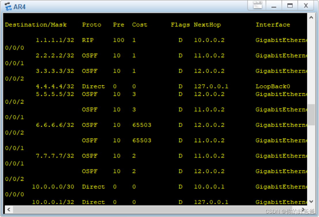
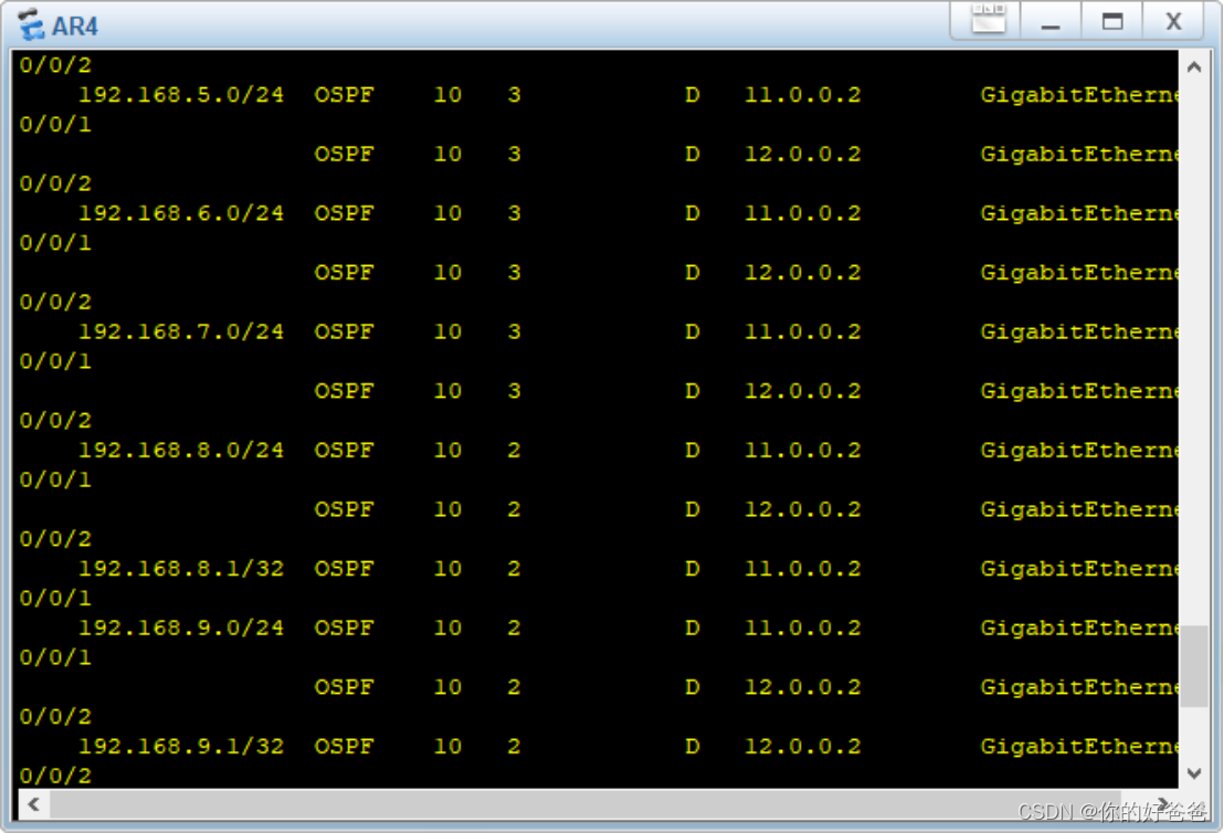
如图为AR4学到的路由表
4.4配置重分发实现内网互通
重分发:
在AR1、4中配置重分发使得rip区域和ospf区域可以相互学习获得网段
AR1:
rip 1
import-route ospf 1
AR4:
ospf 1
import-route rip 1 cost 100
rip 1
import-route ospf 1
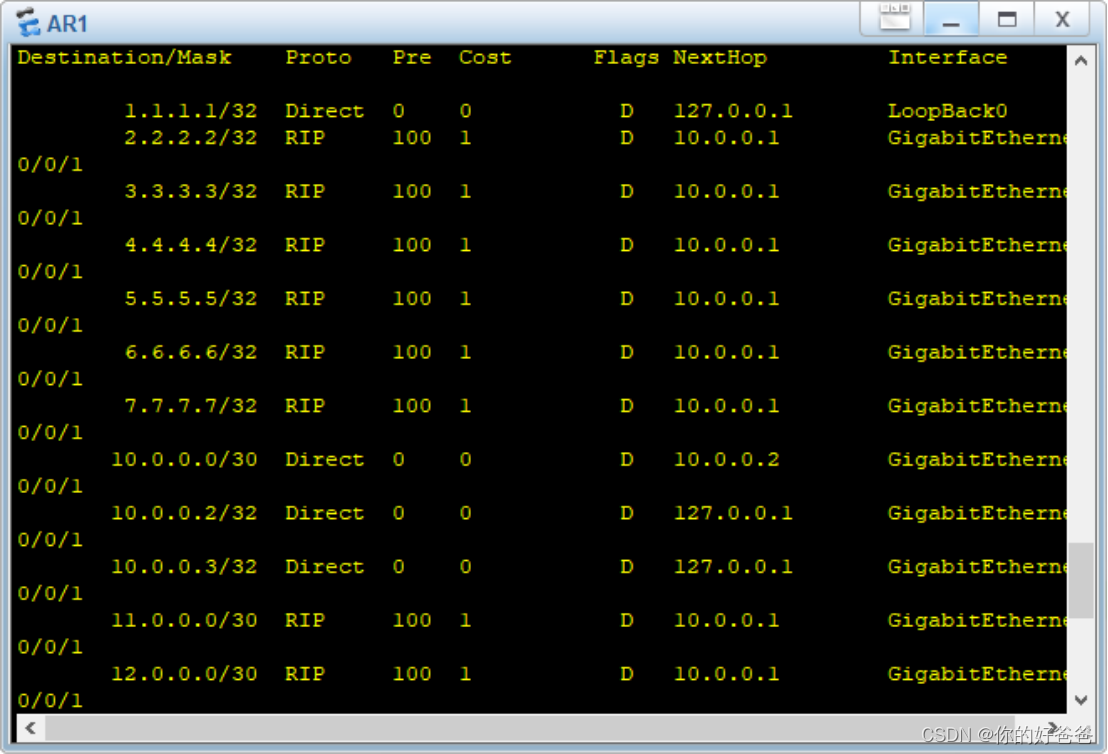
如图是AR1学到的路由条目
验证:
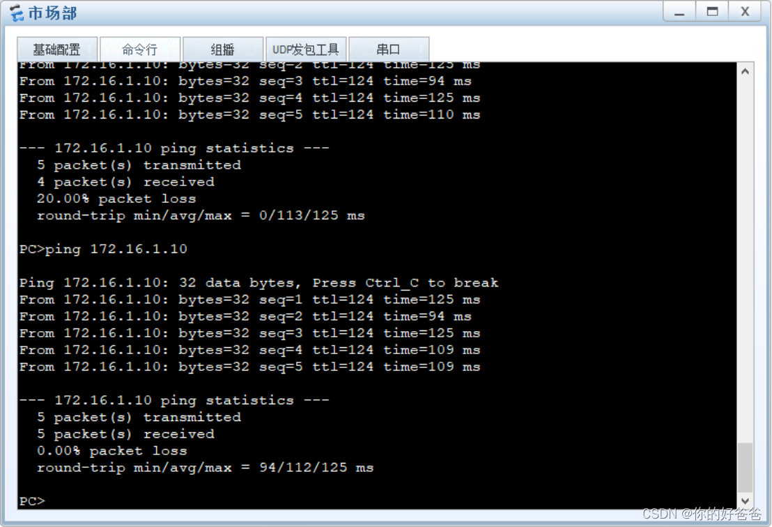
至此内网已经可以全部ping通
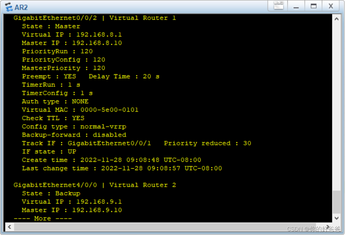
4.5 核心路由器VRRP
核心路由器AR2、3配置双机热备
AR2:
interface gigabitethernet 0/0/1
vrrp vrid 1 virtual-ip 192.168.8.1
vrrp vrid 1 priority 120
vrrp vrid 1 preempt-mode timer delay 20
vrrp vrid 1 track interface g0/0/1 reduced 30
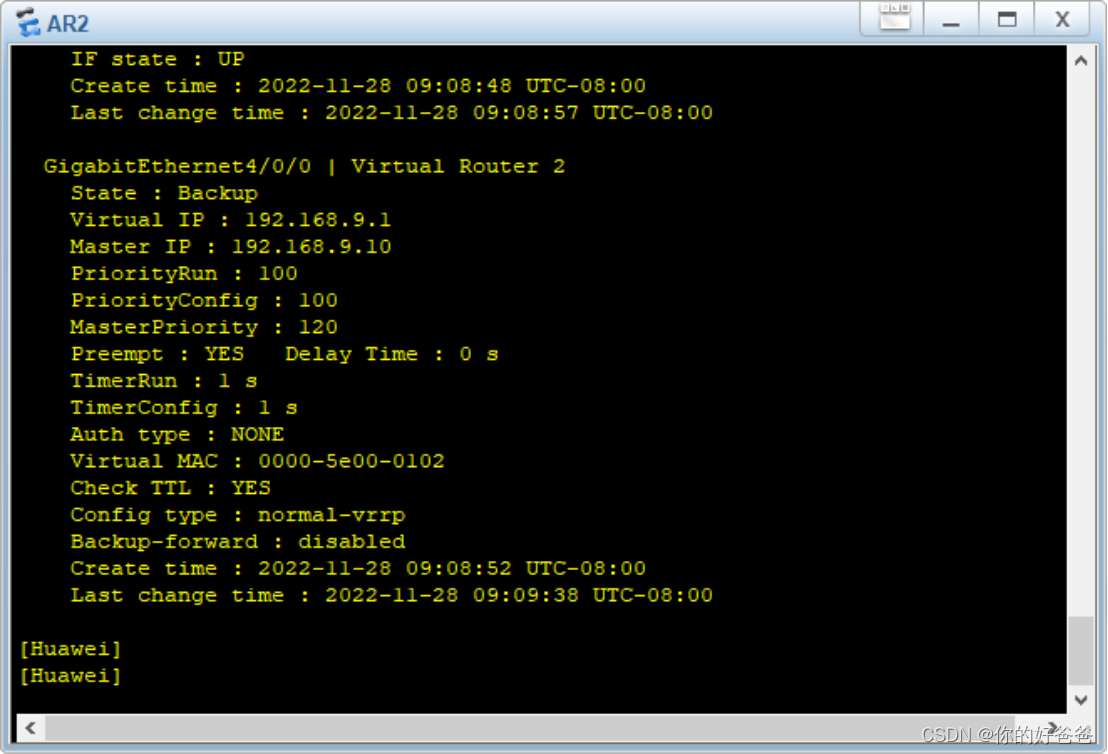
interface gigabitethernet 4/0/0
vrrp vrid 2 virtual-ip 192.168.9.1
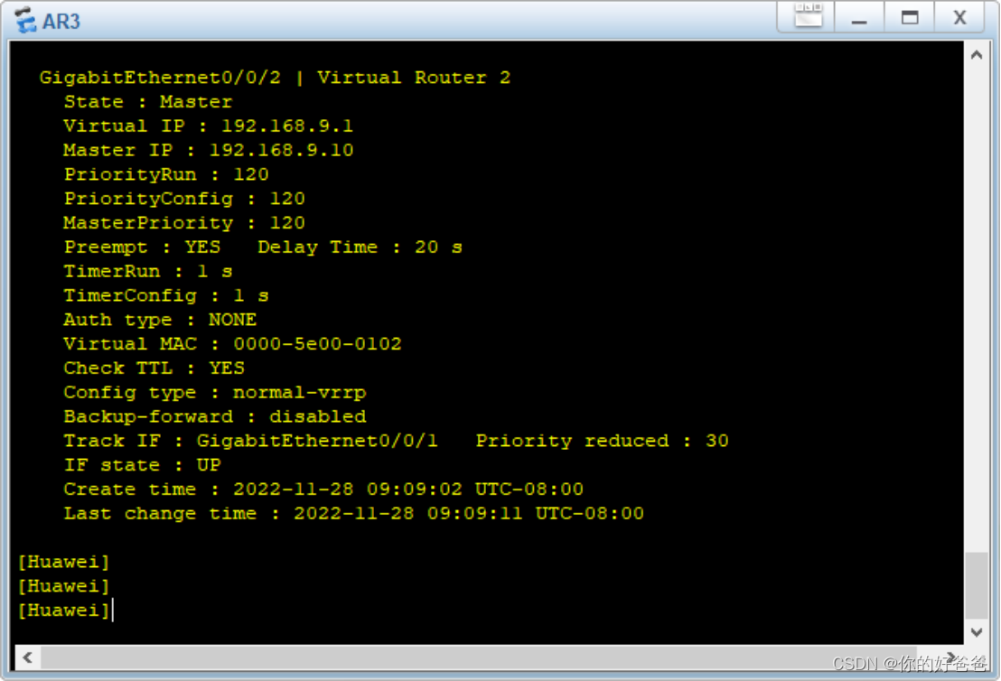
AR3:
interface gigabitethernet 0/0/2
vrrp vrid 2 virtual-ip 192.168.9.1
vrrp vrid 2 priority 120
vrrp vrid 2 preempt-mode timer delay 20
vrrp vrid 2 track interface g0/0/1 reduced 30
interface gigabitethernet 0/0/0
vrrp vrid 1 virtual-ip 192.168.8.1
vrid1完成双机热备:
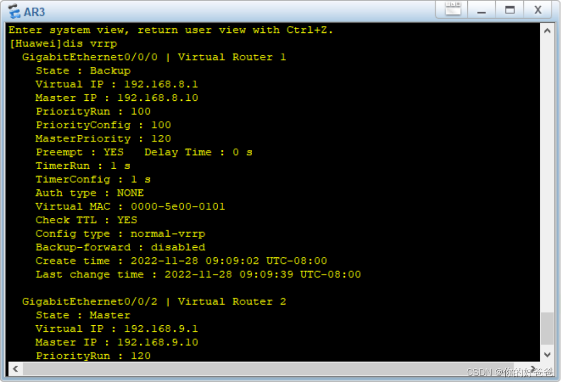
vrid2完成双机热备:
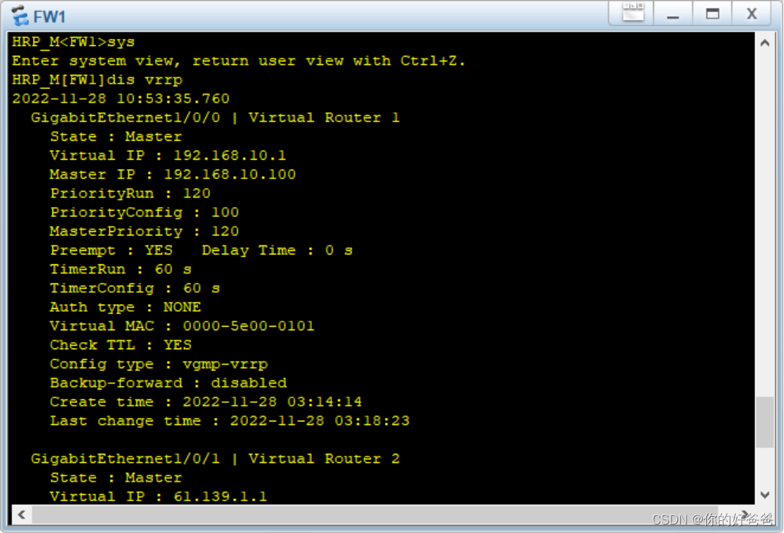
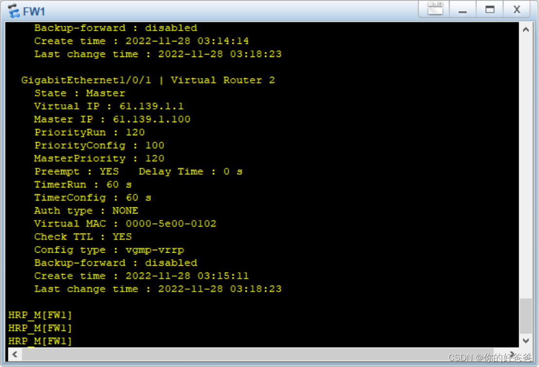
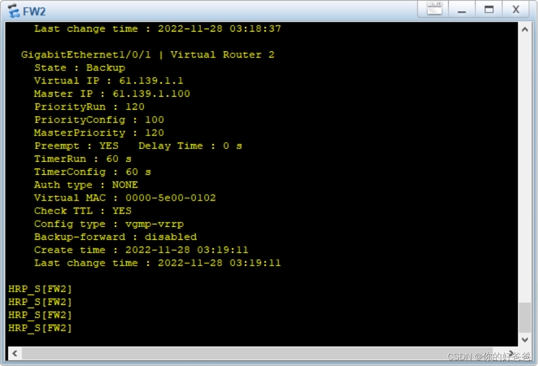
4.6防火墙VRRP
防火墙配置VRRP
FW1:
安全策略配置
firewall zone trust
add int g1/0/0
firewall zone dmz
add int g1/0/2
firewall zone untrust
add int g1/0/1
security-policy
rule name aaa
source-zone local
destination-zone dmz
action permit
quit
rule name trust_to_untrust
source-zone trust
destination-zone untrust
action permit
配置VRRP备份组
int g1/0/0
vrrp vrid 1 virtual-ip 192.168.10.1 active
int g1/0/1
vrrp vrid 2 virtual-ip 61.139.1.1 active
hrp interface GigabitEthernet 1/0/2 remote 172.30.1.2
hrp enable
hrp auto-sync
监控上行链路:
hrp track interface GigabitEthernet 1/0/0
配置快速会话备份功能
hrp mirror session enable
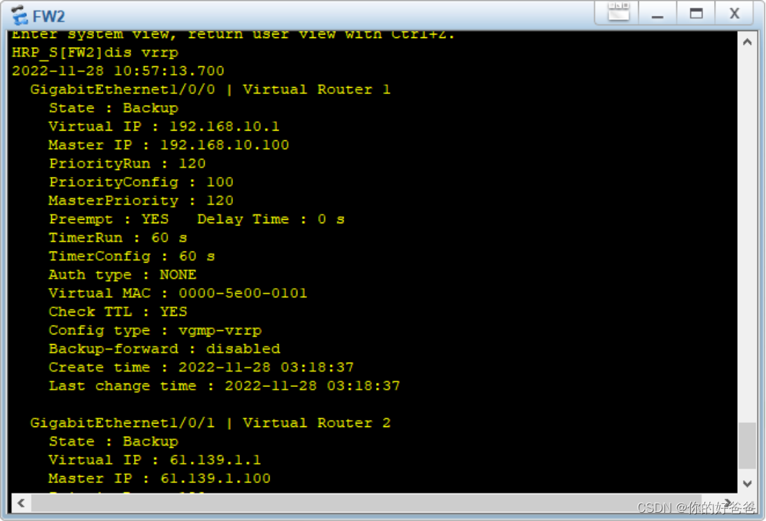
FW2:
安全策略配置
firewall zone trust
add int g1/0/0
firewall zone dmz
add int g1/0/2
firewall zone untrust
add int g1/0/1
security-policy
rule name aaa
source-zone local
destination-zone dmz
action permit
quit
rule name trust_to_untrust
source-zone trust
destination-zone untrust
action permit
配置VRRP备份组
int g1/0/0
vrrp vrid 1 virtual-ip 192.168.10.1 standby
int g1/0/1
vrrp vrid 2 virtual-ip 61.139.1.1 standby
hrp interface GigabitEthernet 1/0/2 remote 172.30.1.1
hrp enable
hrp auto-sync
配置快速会话备份功能
hrp mirror session enable
至此主备份已经完成
FW1:
FW2:


 1741
1741

 被折叠的 条评论
为什么被折叠?
被折叠的 条评论
为什么被折叠?
 到【灌水乐园】发言


