


一:常用基本函数
1.RCC函数库——系统时钟函数——stm32f10x_rcc.h
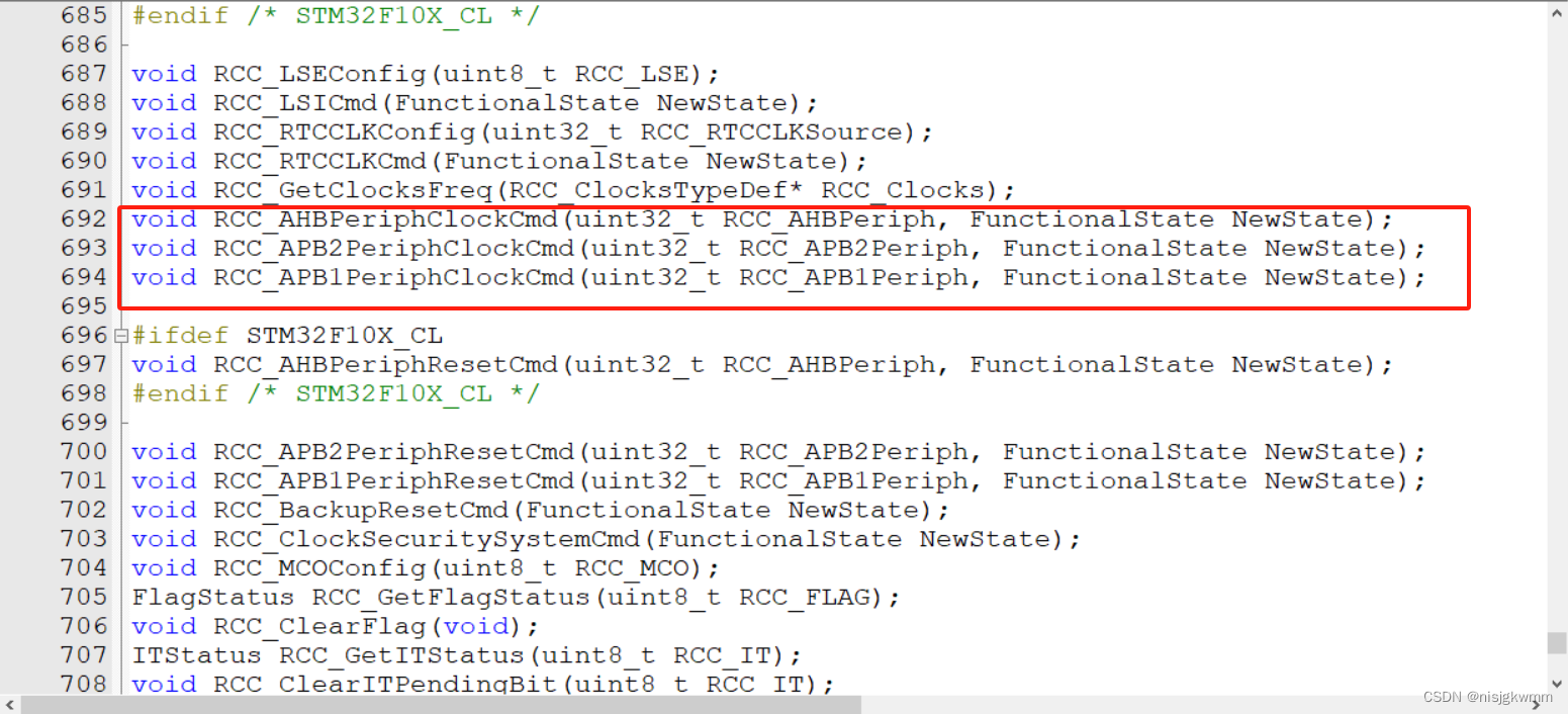
RCC_AHBPeriphClockCmd函数 控制AHB总线的状态。
RCC_APB2PeriphClockCmd函数 控制APB2总线的状态。
RCC_APB1PeriphClockCmd函数 控制APB1总线的状态。
用于根据用的外设开启对的总线状态
2.GPIO函数——输入输出函数——stm32f10x_gpio.h
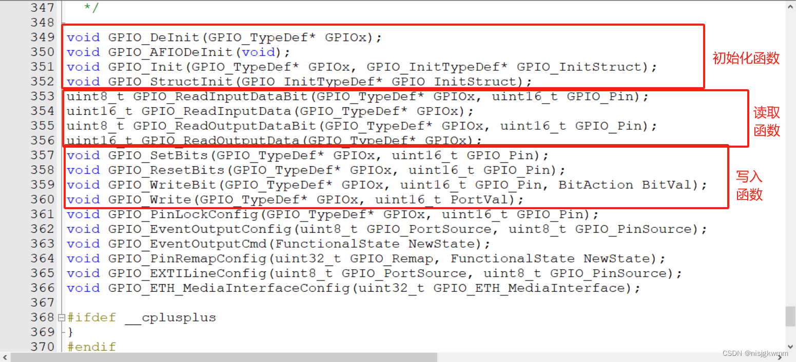
用法示例:初始化GPIO口
GPIO_InitTypeDef GPIO_InitStructure; //定义结构体变量
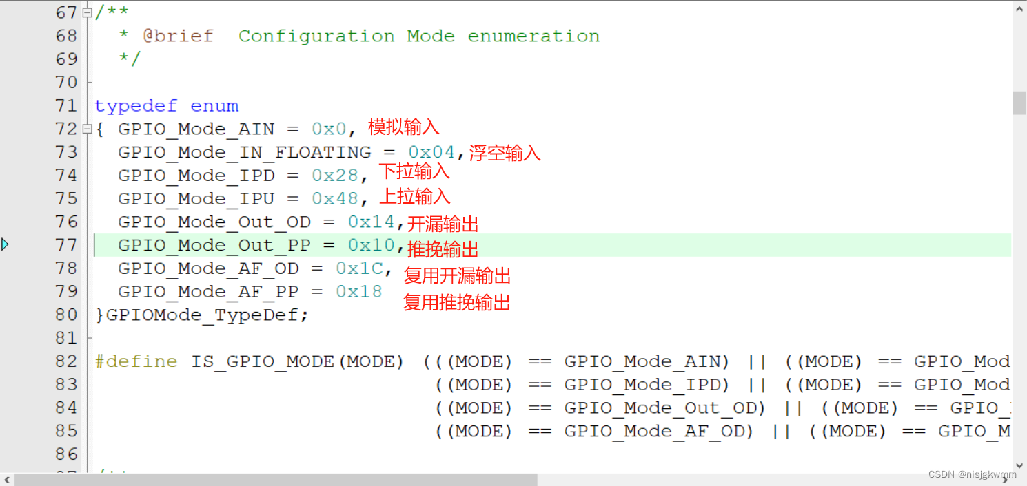
GPIO_InitStructure.GPIO_Mode = GPIO_Mode_Out_PP; //GPIO模式,赋值为推挽输出模式
GPIO_InitStructure.GPIO_Pin = GPIO_Pin_0; //GPIO引脚,赋值为第0号引脚
GPIO_InitStructure.GPIO_Speed = GPIO_Speed_50MHz; //GPIO速度,赋值为50MHz
GPIO_Init(GPIOA, &GPIO_InitStructure); //将赋值后的构体变量传递给GPIO_Init函数
//函数内部会自动根据结构体的参数配置相应寄存器
//实现GPIOA的初始化用法示例:写入一个位
		/*方法1:GPIO_ResetBits设置低电平,GPIO_SetBits设置高电平*/
		GPIO_ResetBits(GPIOA, GPIO_Pin_0);					//将PA0引脚设置为低电平
		Delay_ms(500);										//延时500ms
		GPIO_SetBits(GPIOA, GPIO_Pin_0);					//将PA0引脚设置为高电平
		Delay_ms(500);										//延时500ms

		/*方法2:GPIO_WriteBit设置低/高电平,由Bit_RESET/Bit_SET指定*/
		GPIO_WriteBit(GPIOA, GPIO_Pin_0, Bit_RESET);		//将PA0引脚设置为低电平
		Delay_ms(500);										//延时500ms
		GPIO_WriteBit(GPIOA, GPIO_Pin_0, Bit_SET);			//将PA0引脚设置为高电平
		Delay_ms(500);										//延时500ms

		/*方法3:GPIO_WriteBit设置低/高电平,由数据0/1指定,数据需要强转为BitAction类型*/
		GPIO_WriteBit(GPIOA, GPIO_Pin_0, (BitAction)0);		//将PA0引脚设置为低电平
		Delay_ms(500);										//延时500ms
		GPIO_WriteBit(GPIOA, GPIO_Pin_0, (BitAction)1);		//将PA0引脚设置为高电平
		Delay_ms(500);										//延时500ms
用法示例:写入一4个字节
/*使用GPIO_Write,同时设置GPIOA所有引脚的高低电平,实现LED流水灯*/
		GPIO_Write(GPIOA, ~0x0001);	//0000 0000 0000 0001,PA0引脚为低电平,其他引脚均为高电平,注意数据有按位取反
		Delay_ms(100);				//延时100ms
		GPIO_Write(GPIOA, ~0x0002);	//0000 0000 0000 0010,PA1引脚为低电平,其他引脚均为高电平
		Delay_ms(100);				//延时100ms
		GPIO_Write(GPIOA, ~0x0004);	//0000 0000 0000 0100,PA2引脚为低电平,其他引脚均为高电平
		Delay_ms(100);				//延时100ms
		GPIO_Write(GPIOA, ~0x0008);	//0000 0000 0000 1000,PA3引脚为低电平,其他引脚均为高电平
		Delay_ms(100);				//延时100ms
		GPIO_Write(GPIOA, ~0x0010);	//0000 0000 0001 0000,PA4引脚为低电平,其他引脚均为高电平
		Delay_ms(100);				//延时100ms
		GPIO_Write(GPIOA, ~0x0020);	//0000 0000 0010 0000,PA5引脚为低电平,其他引脚均为高电平
		Delay_ms(100);				//延时100ms
		GPIO_Write(GPIOA, ~0x0040);	//0000 0000 0100 0000,PA6引脚为低电平,其他引脚均为高电平
		Delay_ms(100);				//延时100ms
		GPIO_Write(GPIOA, ~0x0080);	//0000 0000 1000 0000,PA7引脚为低电平,其他引脚均为高电平
		Delay_ms(100);				//延时100ms
用法示例:读取输入字节
	if (GPIO_ReadInputDataBit(GPIOB, GPIO_Pin_1) == 0)			//读PB1输入寄存器的状态,如果为0,则代表按键1按下
	{
		Delay_ms(20);											//延时消抖
		while (GPIO_ReadInputDataBit(GPIOB, GPIO_Pin_1) == 0);	//等待按键松手
		Delay_ms(20);											//延时消抖
		KeyNum = 1;												//置键码为1
	}

	if (GPIO_ReadInputDataBit(GPIOB, GPIO_Pin_11) == 0)			//读PB11输入寄存器的状态,如果为0,则代表按键2按下
	{
		Delay_ms(20);											//延时消抖
		while (GPIO_ReadInputDataBit(GPIOB, GPIO_Pin_11) == 0);	//等待按键松手
		Delay_ms(20);											//延时消抖
		KeyNum = 2;												//置键码为2
	}
用法示例:读取输出字节
void LED1_Turn(void)
{
	if (GPIO_ReadOutputDataBit(GPIOA, GPIO_Pin_0) == 0)		//获取输出寄存器的状态,如果当前引脚输出低电平
	{
		GPIO_SetBits(GPIOA, GPIO_Pin_0);					//则设置PA1引脚为高电平
	}
	else													//否则,即当前引脚输出高电平
	{
		GPIO_ResetBits(GPIOA, GPIO_Pin_0);					//则设置PA1引脚为低电平
	}
}
二:八种工作模式
1.八种模式
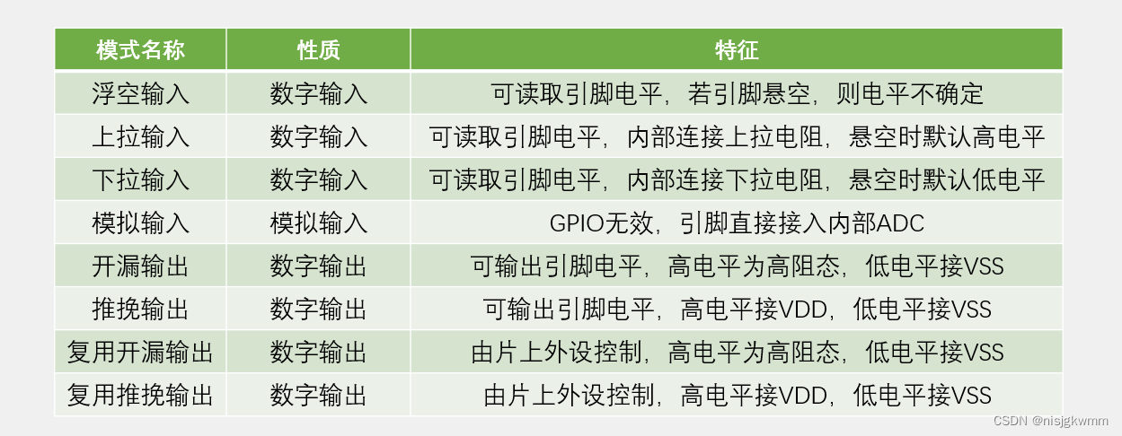
推挽输出高低电平都具有驱动能力,开漏输出低电平有驱动能力高电平无法驱动。一般情况下使用推挽输出即可。PPT有详细电路图
输入避免浮空。


 3923
3923


 被折叠的 条评论
为什么被折叠?
被折叠的 条评论
为什么被折叠?
 到【灌水乐园】发言


