


一、实验需求
1)下载Keil软件,安装stm32库,以及STM32F10xxx参考手册
官网(Keil Product Downloads)下载所需的pack :ARM.CMSIS.3.20.4、Keil.STM32F1xx_DFP.1.0.4
stm32包,这里附带配置MDK所需要的的包。
链接:https://pan.baidu.com/s/1ioKxd2LmbQfxPnkmS9q30w
提取码:7777
STM32F10xxx手册 百度网盘 请输入提取码 密码:18tr
二、实验步骤
为了点亮LED灯,进行以下三个步骤:
1)打开GPIO口的时钟
调用用寄存器功能,为了实现打开A、B、C三个端口的时钟,我们就需要把使能寄存器的相关位赋值为1。
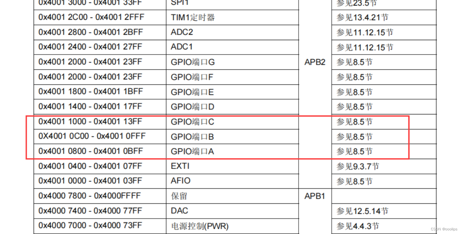
GPIO的地址:
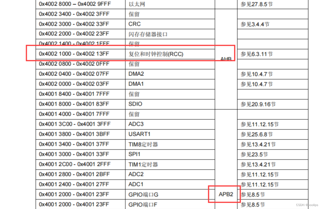
时钟的地址:
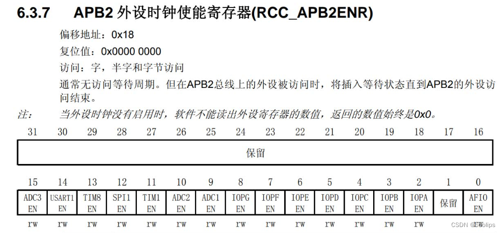
调用时钟使能寄存器
#define RCC_APB2ENR (*(unsigned int *)0x40021018)

// 打开时钟
RCC_APB2ENR |= (1<<3);  // 打开 GPIOB 时钟
RCC_APB2ENR |= (1<<4);  // 打开 GPIOC 时钟
RCC_APB2ENR |= (1<<2);  // 打开 GPIOA 时钟
启用时钟后,我们开始准备端口的相关配置。
2)初始化GPIO口
我们这次实验选择使用推挽输出:
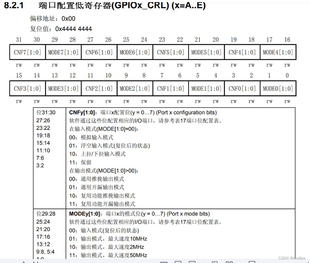
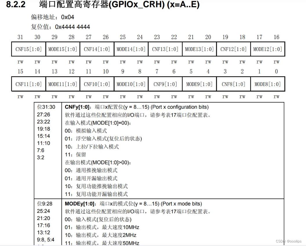
端口0-7为低,端口8-15为高。每个引脚由四个位控制。 A、B、C三种类型的端口,每种类型有16个节点(单片机上接LED灯的端口)可以让我们修改,配置低寄存器可以修改0~7,配置高寄存器可以修改8~15;使用推挽输出,我们需要在相应的节点上把CNF改为00,输出MODE改为01
#define GPIOA_CRL  (*(unsigned int *)0x40010800)
#define GPIOB_CRL  (*(unsigned int *)0x40010C00)
#define GPIOC_CRH  (*(unsigned int *)0x40011004)
//A、B、C三个端口的地址

GPIOA_CRL=0;
GPIOB_CRL=0;
GPIOC_CRH=0;
GPIOA_CRL|=(1<<12);
GPIOB_CRL|=(1<<0);
GPIOC_CRH|=(1<<28);
//我们分别修改了A3、B0、C15端口的输出方式
3)设置高低电平
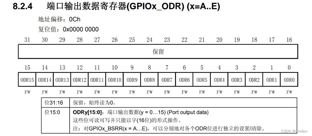
1为高电平,0为低电平
#define GPIOA_ODR  (*(unsigned int *)0x4001080C)
#define GPIOB_ODR  (*(unsigned int *)0x40010C0C)
#define GPIOC_ODR  (*(unsigned int *)0x4001100C)
//ABC三个端口的输出数据

	GPIOA_ODR=0;
	GPIOB_ODR=0;
	GPIOC_ODR=0;
//置0时LED熄灭
    GPIOA_ODR|=(1<<3);
//A3亮
	GPIOB_ODR|=(1<<0);
//B0亮
	GPIOC_ODR|=(1<<15);
//C15亮,另外具体怎么亮还要取决于你的小灯泡是如何接的
总代码:
#define GPIOB_BASE 0x40010C00
#define GPIOC_BASE 0x40011000
#define GPIOA_BASE 0x40010800

#define RCC_APB2ENR (*(unsigned int *)0x40021018)

#define GPIOB_CRH (*(unsigned int *)0x40010C04)
#define GPIOC_CRH (*(unsigned int *)0x40011004)
#define GPIOA_CRL (*(unsigned int *)0x40010800)

#define GPIOB_ODR (*(unsigned int *)0x40010C0C)
#define GPIOC_ODR (*(unsigned int *)0x4001100C)
#define GPIOA_ODR (*(unsigned int *)0x4001080C)


void SystemInit(void);
void Delay_ms(volatile  unsigned  int);
void A_LED_LIGHT(void);
void B_LED_LIGHT(void);
void C_LED_LIGHT(void);
void Delay_ms( volatile  unsigned  int  t)
{
     unsigned  int  i;
     while(t--)
         for (i=0;i<800;i++);
}

void A_LED_LIGHT(){
	GPIOA_ODR=0x0<<4;		//PA4低电平
	GPIOB_ODR=0x1<<9;		//PB9高电平
	GPIOC_ODR=0x1<<15;		//PC15高电平
}
void B_LED_LIGHT(){
	GPIOA_ODR=0x1<<4;		//PA4高电平
	GPIOB_ODR=0x0<<9;		//PB9低电平
	GPIOC_ODR=0x1<<15;		//PC15高电平
}
void C_LED_LIGHT(){
	GPIOA_ODR=0x1<<4;		//PA4高电平
	GPIOB_ODR=0x1<<9;		//PB9高电平
	GPIOC_ODR=0x0<<15;		//PC15低电平
}

int main(){
	int j=100;
	// 开启时钟
	RCC_APB2ENR |= (1<<3); // 开启 GPIOB 时钟
	RCC_APB2ENR |= (1<<4); // 开启 GPIOC 时钟
	RCC_APB2ENR |= (1<<2); // 开启 GPIOA 时钟


	// 设置 GPIO 为推挽输出
	GPIOB_CRH&= 0xffffff0f;	//设置位 清零
	GPIOB_CRH|=0x00000020;  //PB9推挽输出

	GPIOC_CRH &= 0x0fffffff; //设置位 清零
	GPIOC_CRH|=0x30000000;  //PC15推挽输出


	GPIOA_CRL &= 0xfff0ffff; //设置位 清零
	GPIOA_CRL|=0x00010000; //PA4推挽输出

	// 3个LED初始化为不亮(即高点位)
	GPIOB_ODR |= (1<<9);
	GPIOC_ODR |= (1<<15);
	GPIOA_ODR |= (1<<4);

	while(j){

		B_LED_LIGHT();
		Delay_ms(1000000);

		C_LED_LIGHT();
		Delay_ms(1000000);

		A_LED_LIGHT();
		Delay_ms(1000000);
	}

}


void SystemInit(){

}
三、效果展示
流水灯
四、调用开发板自带LED
由于STM32最小系统核心板焊接好一个LED我们可以直接调用,它的位置在PC13,我们准备修改代码来实现点亮它。
效果展示:
PC13
烧录代码
#define GPIOB_BASE 0x40010C00
#define GPIOC_BASE 0x40011000
#define GPIOA_BASE 0x40010800

#define RCC_APB2ENR (*(unsigned int *)0x40021018)

#define GPIOB_CRH (*(unsigned int *)0x40010C04)
#define GPIOC_CRH (*(unsigned int *)0x40011004)
#define GPIOA_CRL (*(unsigned int *)0x40010800)

#define GPIOB_ODR (*(unsigned int *)0x40010C0C)
#define GPIOC_ODR (*(unsigned int *)0x4001100C)
#define GPIOA_ODR (*(unsigned int *)0x4001080C)


void SystemInit(void);
void Delay_ms(volatile  unsigned  int);
void A_LED_LIGHT(void);
void B_LED_LIGHT(void);
void C_LED_LIGHT(void);
void Delay_ms( volatile  unsigned  int  t)
{
     unsigned  int  i;
     while(t--)
         for (i=0;i<800;i++);
}

void A_LED_LIGHT(){
	GPIOA_ODR=0x0<<4;		//PA4低电平
	GPIOB_ODR=0x1<<9;		//PB9高电平
	GPIOC_ODR=0x1<<13;		//PC13高电平
}
void B_LED_LIGHT(){
	GPIOA_ODR=0x1<<4;		//PA4高电平
	GPIOB_ODR=0x0<<9;		//PB9低电平
	GPIOC_ODR=0x1<<13;		//PC13高电平
}
void C_LED_LIGHT(){
	GPIOA_ODR=0x1<<4;		//PA4高电平
	GPIOB_ODR=0x1<<9;		//PB9高电平
	GPIOC_ODR=0x0<<13;		//PC13低电平
}

int main(){
	int j=100;
	// 开启时钟
	RCC_APB2ENR |= (1<<3); // 开启 GPIOB 时钟
	RCC_APB2ENR |= (1<<4); // 开启 GPIOC 时钟
	RCC_APB2ENR |= (1<<2); // 开启 GPIOA 时钟


	// 设置 GPIO 为推挽输出
	GPIOB_CRH&= 0xffffff0f;	//设置位 清零
	GPIOB_CRH|=0x00000020;  //PB9推挽输出

	GPIOC_CRH &= 0xff0fffff; //设置位 清零
	GPIOC_CRH|=0x00300000;  //PC15推挽输出


	GPIOA_CRL &= 0xfff0ffff; //设置位 清零
	GPIOA_CRL|=0x00010000; //PA4推挽输出

	// 3个LED初始化为不亮(即高点位)
	GPIOB_ODR |= (1<<9);
	GPIOC_ODR |= (1<<13);
	GPIOA_ODR |= (1<<4);

	while(j){

		B_LED_LIGHT();
		Delay_ms(2000);//单片机上2000    100

		C_LED_LIGHT();
		Delay_ms(3000);//单片机上3000    200

		A_LED_LIGHT();
		Delay_ms(3000);//单片机上3000    200
	}

}


void SystemInit(){

}


 551
551


 被折叠的 条评论
为什么被折叠?
被折叠的 条评论
为什么被折叠?
 到【灌水乐园】发言


