


1. 掌控板使用的OLED显示屏
SH1106是一款单片CMOS OLED/PLED驱动器,带控制器,用于有机/聚合物发光二极管点阵图形显示系统。SH1106由132个分段、64个共用点组成,可支持132 x 64的最大显示分辨率。它是专为共阴极型OLED面板而设计的。SH1106内置对比度控制、显示RAM振荡器和高效Dc-Dc转换器,减少外部组件数量和功耗。SH1106适用于各种紧凑便携的应用,如手机的子显示器、计算器、MP3播放器等。
SSD1306和SH1106的区别见
https://blog.csdn.net/fbgbhvgv/article/details/131456957
https://blog.csdn.net/weixin_42150905/article/details/117511216
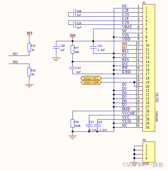
掌控板官方给的电路手册中给的是SSD1106,如下图所示:
2. 添加库文件
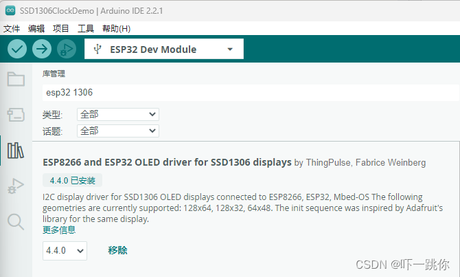
(1)在arduino IDE的库管理中输入"esp32 1306",安装ESP8266 and ESP32 OLED driver for SSD1306 displays库,如下图所示。
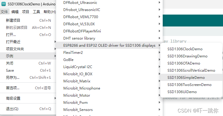
(2)在文件菜单中的示例子菜单下找到ESP8266 and ESP32 OLED driver for SSD1306 displays中的SSD1306SimpleDemo示例,如图所示。
3. 修改代码
(1)在打开的SSD1306SimpleDemo.ino中,讲第35行
#include "SSD1306Wire.h" // legacy: #include "SSD1306.h"
注释掉。
//#include "SSD1306Wire.h" // legacy: #include "SSD1306.h"
(2)将第36行
// OR #include "SH1106Wire.h" // legacy: #include "SH1106.h"
修改为
#include "SH1106Wire.h"
(3)将第54行
SSD1306Wire display(0x3c, SDA, SCL); // ADDRESS, SDA, SCL - SDA and SCL usually populate automatically based on your board's pins_arduino.h e.g. https://github.com/esp8266/Arduino/blob/master/variants/nodemcu/pins_arduino.h
注释掉
//SSD1306Wire display(0x3c, SDA, SCL); // ADDRESS, SDA, SCL - SDA and SCL usually populate automatically based on your board's pins_arduino.h e.g. https://github.com/esp8266/Arduino/blob/master/variants/nodemcu/pins_arduino.h
(4)根据电路图中,SDA连接的是IO23,SCL连接的是IO22,将第57行
SH1106Wire display(0x3c, SDA, SCL); // ADDRESS, SDA, SCL
修改为
SH1106Wire display(0x3c, 23, 22); // ADDRESS, SDA, SCL
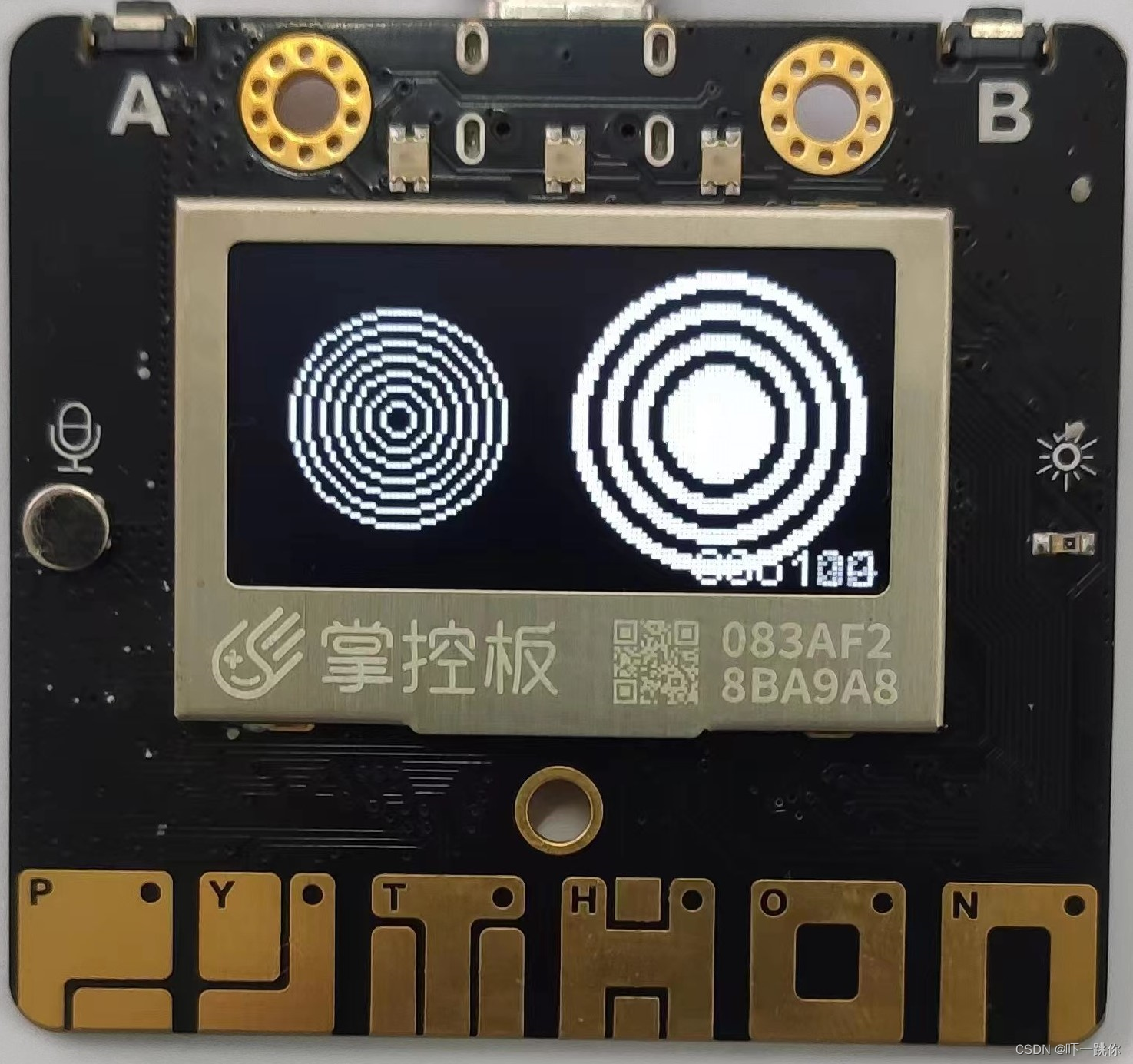
4.上传运行。
下图是运行界面之一。
5. 简化代码,只显示画圆的功能。
#include <Wire.h>
#include "SH1106Wire.h"

SH1106Wire display(0x3c, 23, 22);     // SDA=23, SCL=22

void setup() {
  // Initialising the UI will init the display too.
  display.init();
  display.flipScreenVertically();
}

void drawCircleDemo() {
  for (int i = 1; i < 8; i++) {
    display.setColor(WHITE);
    display.drawCircle(32, 32, i * 3);
    if (i % 2 == 0) {
      display.setColor(BLACK);
    }
    display.fillCircle(96, 32, 32 - i * 3);
  }
}
void loop() {
  // clear the display
  display.clear();
  // draw the current demo method
  drawCircleDemo();
  // write the buffer to the display
  display.display();
  delay(10);
}


 1308
1308


 被折叠的 条评论
为什么被折叠?
被折叠的 条评论
为什么被折叠?
 到【灌水乐园】发言


