


 超级会员免费看
本系列基于https://github.com/espressif/esp32-camera工程代码,对于代码的细节进行深入解析,弥补网上目前此类文章短缺的不足。
本文内容参考:
esp32-camera入门(基于ESP-IDF)_esp32 camera-CSDN博客
特此致谢!
一、OV5640初始化
1. 配置接线和驱动
#include "esp_camera.h"

//WROVER-KIT PIN Map
#define CAM_PIN_PWDN    -1 //power down is not used
#define CAM_PIN_RESET   -1 //software reset will be performed
#define CAM_PIN_XCLK    21
#define CAM_PIN_SIOD    26
#define CAM_PIN_SIOC    27

#define CAM_PIN_D7      35
#define CAM_PIN_D6      34
#define CAM_PIN_D5      39
#define CAM_PIN_D4      36
#define CAM_PIN_D3      19
#define CAM_PIN_D2      18
#define CAM_PIN_D1       5
#define CAM_PIN_D0       4
#define CAM_PIN_VSYNC   25
#define CAM_PIN_HREF    23
#define CAM_PIN_PCLK    22

static camera_config_t camera_config = {
    .pin_pwdn  = CAM_PIN_PWDN,
    .pin_reset = CAM_PIN_RESET,
    .pin_xclk = CAM_PIN_XCLK,
    .pin_sccb_sda = CAM_PIN_SIOD,
    .pin_sccb_scl = CAM_PIN_SIOC,

    .pin_d7 = CAM_PIN_D7,
    .pin_d6 = CAM_PIN_D6,
    .pin_d5 = CAM_PIN_D5,
    .pin_d4 = CAM_PIN_D4,
    .pin_d3 = CAM_PIN_D3,
    .pin_d2 = CAM_PIN_D2,
    .pin_d1 = CAM_PIN_D1,
    .pin_d0 = CAM_PIN_D0,
    .pin_vsync = CAM_PIN_VSYNC,
    .pin_href = CAM_PIN_HREF,
    .pin_pclk = CAM_PIN_PCLK,

    .xclk_freq_hz = 20000000,//EXPERIMENTAL: Set to 16MHz on ESP32-S2 or ESP32-S3 to enable EDMA mode
    .ledc_timer = LEDC_TIMER_0,
    .ledc_channel = LEDC_CHANNEL_0,

    .pixel_format = PIXFORMAT_JPEG,//YUV422,GRAYSCALE,RGB565,JPEG
    .frame_size = FRAMESIZE_UXGA,//QQVGA-UXGA, For ESP32, do not use sizes above QVGA when not JPEG. The performance of the ESP32-S series has improved a lot, but JPEG mode always gives better frame rates.

    .jpeg_quality = 12, //0-63, for OV series camera sensors, lower number means higher quality
    .fb_count = 1, //When jpeg mode is used, if fb_count more than one, the driver will work in continuous mode.
    .grab_mode = CAMERA_GRAB_WHEN_EMPTY//CAMERA_GRAB_LATEST. Sets when buffers should be filled
};

esp_err_t camera_init(){
    //power up the camera if PWDN pin is defined
    if(CAM_PIN_PWDN != -1){
        pinMode(CAM_PIN_PWDN, OUTPUT);
        digitalWrite(CAM_PIN_PWDN, LOW);
    }

    //initialize the camera
    esp_err_t err = esp_camera_init(&camera_config);
    if (err != ESP_OK) {
        ESP_LOGE(TAG, "Camera Init Failed");
        return err;
    }

    return ESP_OK;
}

esp_err_t camera_capture(){
    //acquire a frame
    camera_fb_t * fb = esp_camera_fb_get();
    if (!fb) {
        ESP_LOGE(TAG, "Camera Capture Failed");
        return ESP_FAIL;
    }
    //replace this with your own function
    process_image(fb->width, fb->height, fb->format, fb->buf, fb->len);

    //return the frame buffer back to the driver for reuse
    esp_camera_fb_return(fb);
    return ESP_OK;
}
一段一段来看。先来看第一段代码:
static camera_config_t camera_config = {
    .pin_pwdn  = CAM_PIN_PWDN,
    .pin_reset = CAM_PIN_RESET,
    .pin_xclk = CAM_PIN_XCLK,
    .pin_sccb_sda = CAM_PIN_SIOD,
    .pin_sccb_scl = CAM_PIN_SIOC,

    .pin_d7 = CAM_PIN_D7,
    .pin_d6 = CAM_PIN_D6,
    .pin_d5 = CAM_PIN_D5,
    .pin_d4 = CAM_PIN_D4,
    .pin_d3 = CAM_PIN_D3,
    .pin_d2 = CAM_PIN_D2,
    .pin_d1 = CAM_PIN_D1,
    .pin_d0 = CAM_PIN_D0,
    .pin_vsync = CAM_PIN_VSYNC,
    .pin_href = CAM_PIN_HREF,
    .pin_pclk = CAM_PIN_PCLK,

    .xclk_freq_hz = 20000000,//EXPERIMENTAL: Set to 16MHz on ESP32-S2 or ESP32-S3 to enable EDMA mode
    .ledc_timer = LEDC_TIMER_0,
    .ledc_channel = LEDC_CHANNEL_0,

    .pixel_format = PIXFORMAT_JPEG,//YUV422,GRAYSCALE,RGB565,JPEG
    .frame_size = FRAMESIZE_UXGA,//QQVGA-UXGA, For ESP32, do not use sizes above QVGA when not JPEG. The performance of the ESP32-S series has improved a lot, but JPEG mode always gives better frame rates.

    .jpeg_quality = 12, //0-63, for OV series camera sensors, lower number means higher quality
    .fb_count = 1, //When jpeg mode is used, if fb_count more than one, the driver will work in continuous mode.
    .grab_mode = CAMERA_GRAB_WHEN_EMPTY//CAMERA_GRAB_LATEST. Sets when buffers should be filled
};
camera_config_t的定义在components\esp32-camera\driver\include\esp_camera.h中,代码如下:
/**
* @brief Configuration structure for camera initialization
*/
typedef struct {
int pin_pwdn; /*!< GPIO pin for camera power down line */
int pin_reset; /*!< GPIO pin for camera reset line */
int pin_xclk; /*!< GPIO pin for camera XCLK line */
union {
int pin_sccb_sda; /*!< GPIO pin for camera SDA line */
int pin_sscb_sda __attribute__((deprecated("please use pin_sccb_sda instead"))); /*!< GPIO pin for camera SDA line (legacy name) */
};
union {
int pin_sccb_scl; /*!< GPIO pin for camera SCL line */
int pin_sscb_scl __attribute__((deprecated("please use pin_sccb_scl instead"))); /*!< GPIO pin for camera SCL line (legacy name) */
};
int pin_d7; /*!< GPIO pin for camera D7 line */
int pin_d6; /*!< GPIO pin for camera D6 line */
int pin_d5; /*!< GPIO pin for camera D5 line */
int pin_d4; /*!< GPIO pin for camera D4 line */
int pin_d3; /*!< GPIO pin for camera D3 line */
int pin_d2; /*!< GPIO pin for camera D2 line */
int pin_d1; /*!< GPIO pin for camera D1 line */
int pin_d0; /*!< GPIO pin for camera D0 line */
int pin_vsync; /*!< GPIO pin for camera VSYNC line */
int pin_href; /*!< GPIO pin for camera HREF line */
int pin_pclk; /*!< GPIO pin for camera PCLK line */
int xclk_freq_hz; /*!< Frequency of XCLK signal, in Hz. EXPERIMENTAL: Set to 16MHz on ESP32-S2 or ESP32-S3 to enable EDMA mode */
ledc_timer_t ledc_timer; /*!< LEDC timer to be used for generating XCLK */
ledc_channel_t ledc_channel; /*!< LEDC channel to be used for generating XCLK */
pixformat_t pixel_format; /*!< Format of the pixel data: PIXFORMAT_ + YUV422|GRAYSCALE|RGB565|JPEG */
framesize_t frame_size; /*!< Size of the output image: FRAMESIZE_ + QVGA|CIF|VGA|SVGA|XGA|SXGA|UXGA */
int jpeg_quality; /*!< Quality of JPEG output. 0-63 lower means higher quality */
size_t fb_count; /*!< Number of frame buffers to be allocated. If more than one, then each frame will be acquired (double speed) */
camera_fb_location_t fb_location; /*!< The location where the frame buffer will be allocated */
camera_grab_mode_t grab_mode; /*!< When buffers should be filled */
#if CONFIG_CAMERA_CONVERTER_ENABLED
camera_conv_mode_t conv_mode; /*!< RGB<->YUV Conversion mode */
#endif
int sccb_i2c_port; /*!< If pin_sccb_sda is -1, use the already configured I2C bus by number */
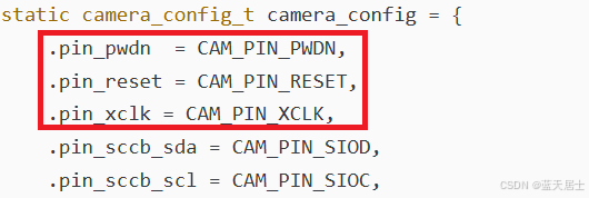
} camera_config_t;注释说得清楚,camera_config_t结构是摄像机初始化配置结构。即使就这一个camera_config_t,也得分段来讲。先来看第一段:
typedef struct {
    int pin_pwdn;                   /*!< GPIO pin for camera power down line */
    int pin_reset;                  /*!< GPIO pin for camera reset line */
    int pin_xclk;                   /*!< GPIO pin for camera XCLK line */
    ……
} camera_config_t;
这三个成员分别对应了OV5640的PWDN、RESETB、XVCLK引脚。如下图所示:


后文书在讲OV5640上电时序的时候,这三个引脚(PWDN、RESETB、XVCLK)还会用到,到时候再深入解析。
回到示例代码中。camera_config_t结构这前三个成员已经弄清楚了,但是具体赋的是什么值,还要弄清楚。参见上边代码片段:
CAM_PIN_PWDN、CAM_PIN_RESET、CAM_PIN_XCLK三个都是宏,就在代码开头处。定义如下:
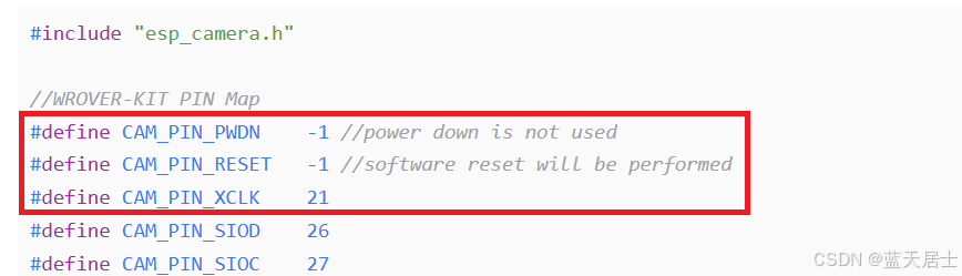
实际上这三个PIN的具体定义是视具体硬件而定的。看ESP32(或ESP32-S3)主芯片使用的哪个引脚,这里就定义为哪个。如果没有连到主芯片,就定义为-1,即未使用。
这样,camera_config_t结构及其实例camera_config的第1段代码就解析完了,下一回继续往下解析。


 1079
1079

 被折叠的 条评论
为什么被折叠?
被折叠的 条评论
为什么被折叠?
 到【灌水乐园】发言


