


目录
前言
调试使用ESP-WROOM-32作为SPI SLAVE 和STM32进行通信,粗略测试通信速度。
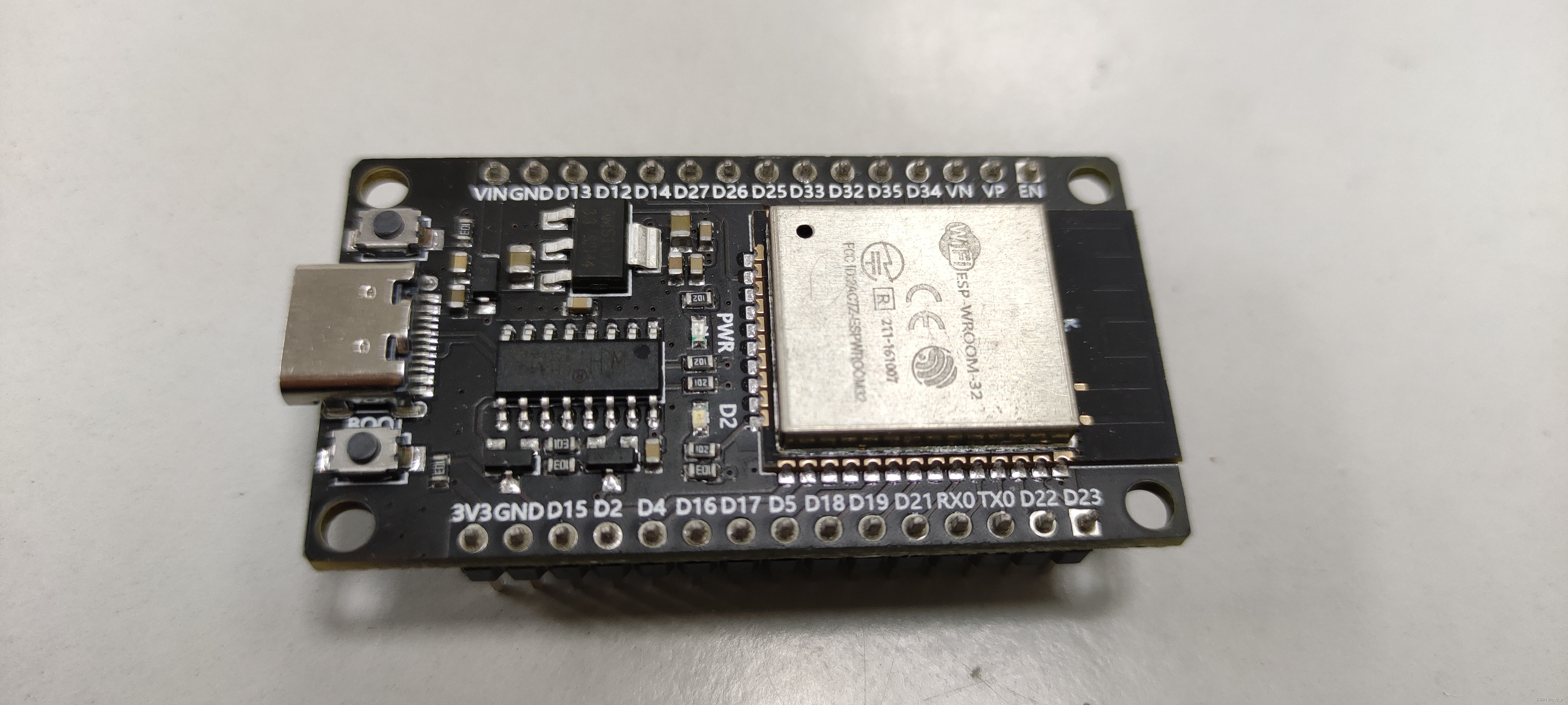
一、ESP32 SLAVE 配置
ESP32 SLAVE 使用乐鑫官方的SDK进行配置,开发使用VSCODE+ESP-IDF
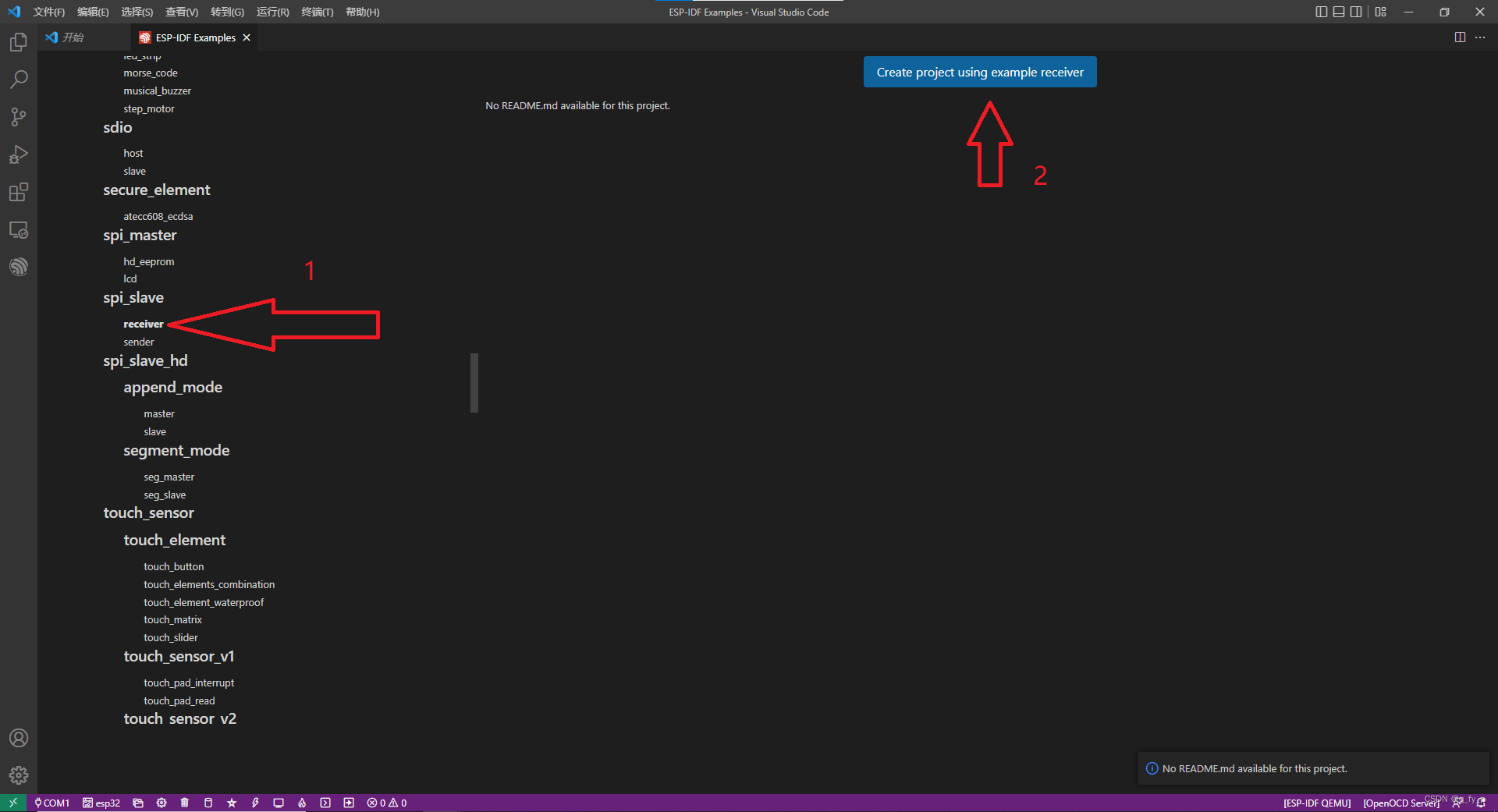
(1)打开官方例程
打开软件,安装乐鑫ESP-IDF
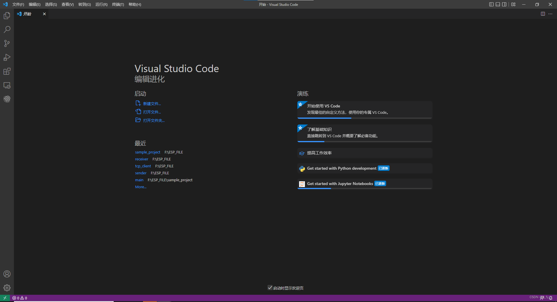
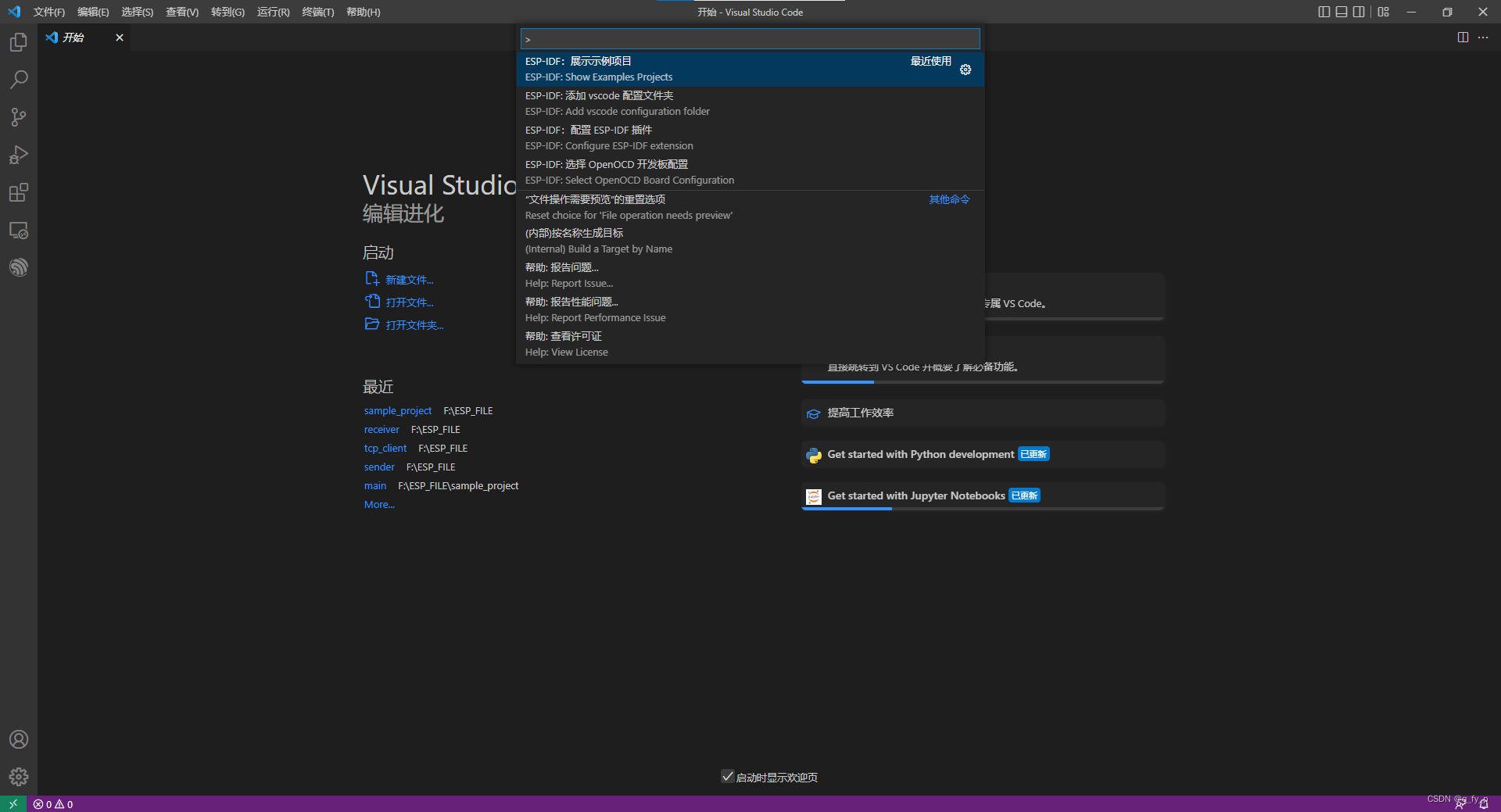
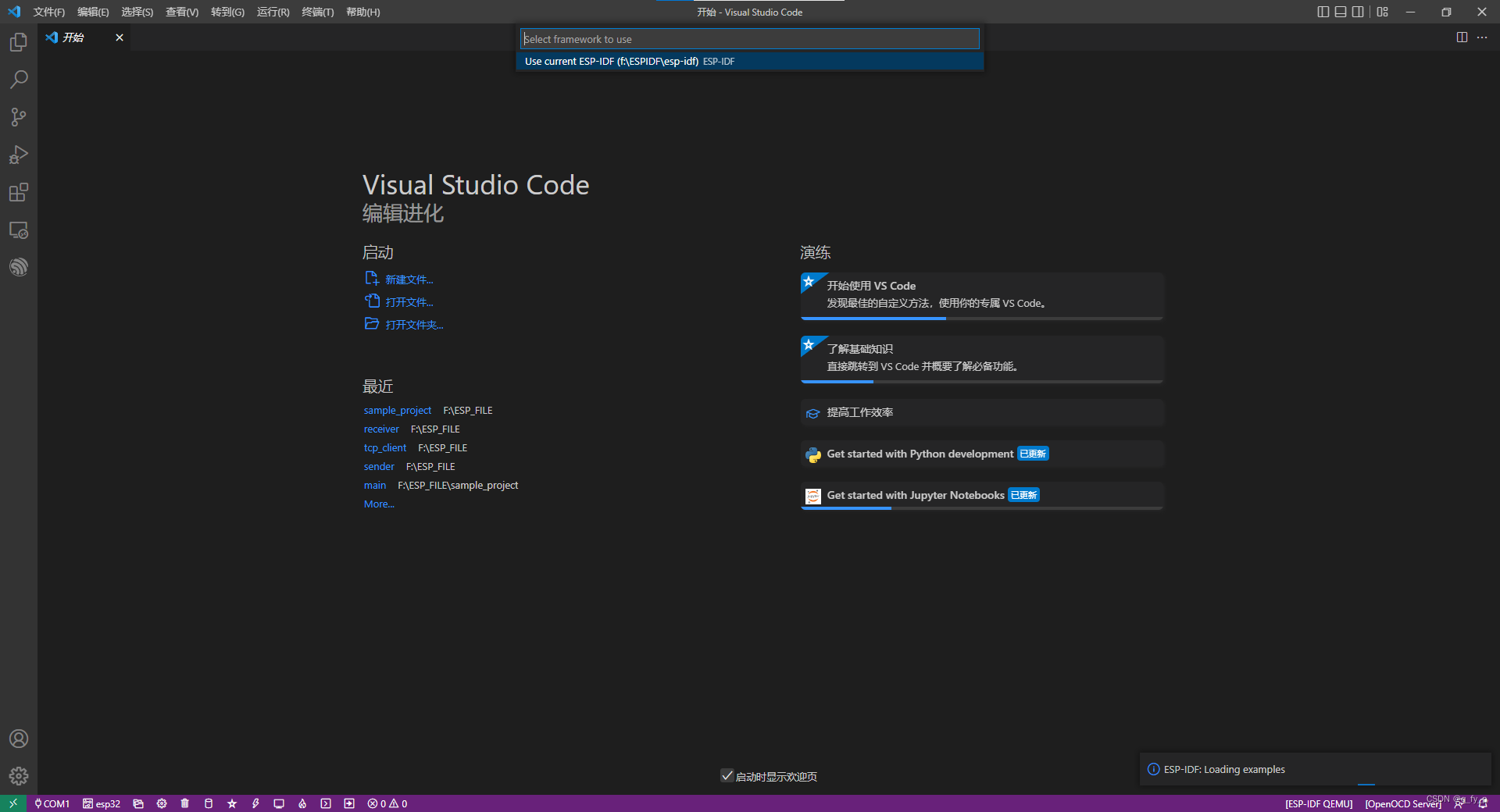
快捷键F1,输入ESP-SHOW,点击ESP-IDF:展示示例项目,最后选择的路径不建议有中文
(2)配置例程
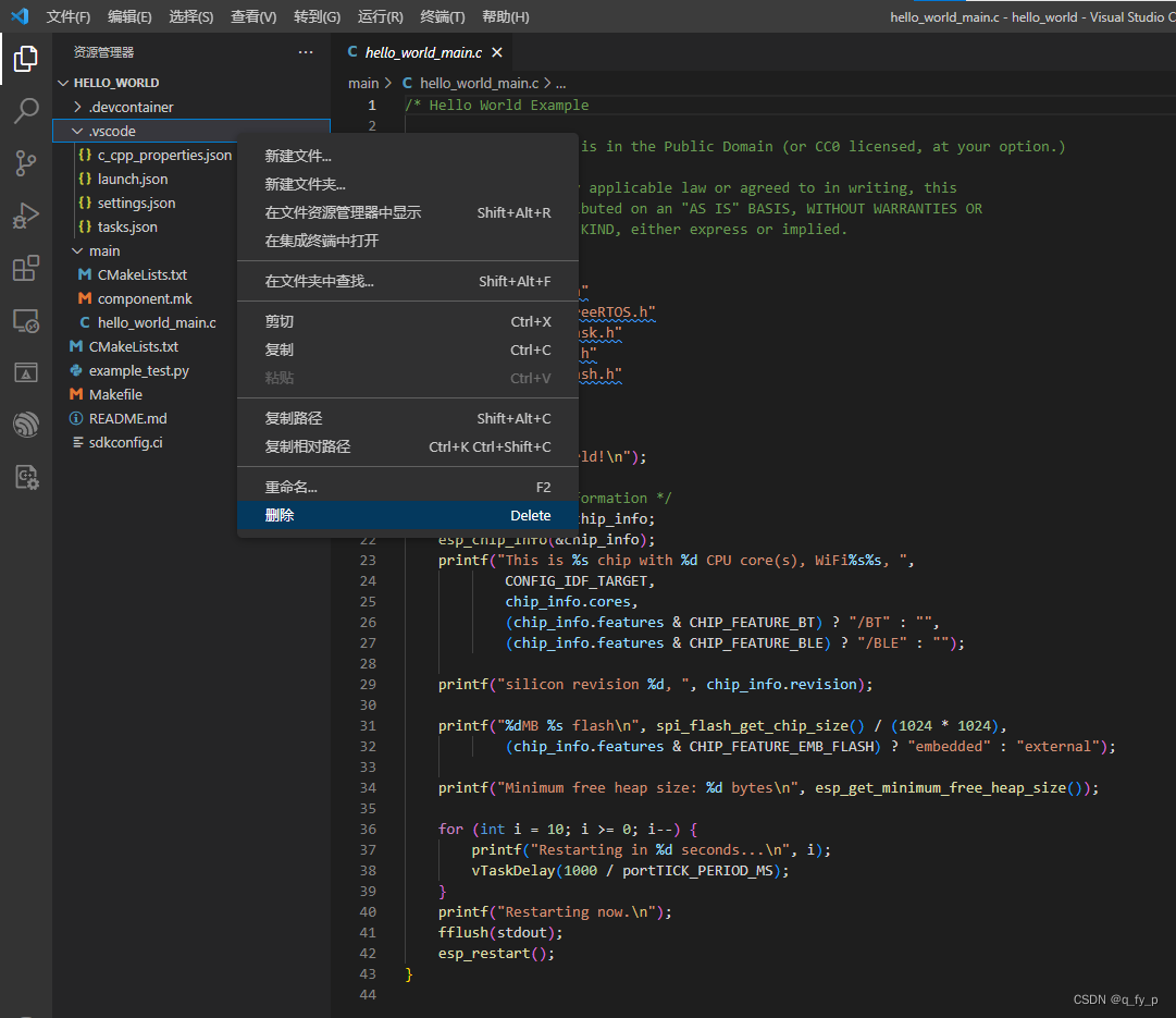
对于刚打开的工程,如果出现头文件引用找不到的情况(有波浪线):
1.删除工程下的.vscode
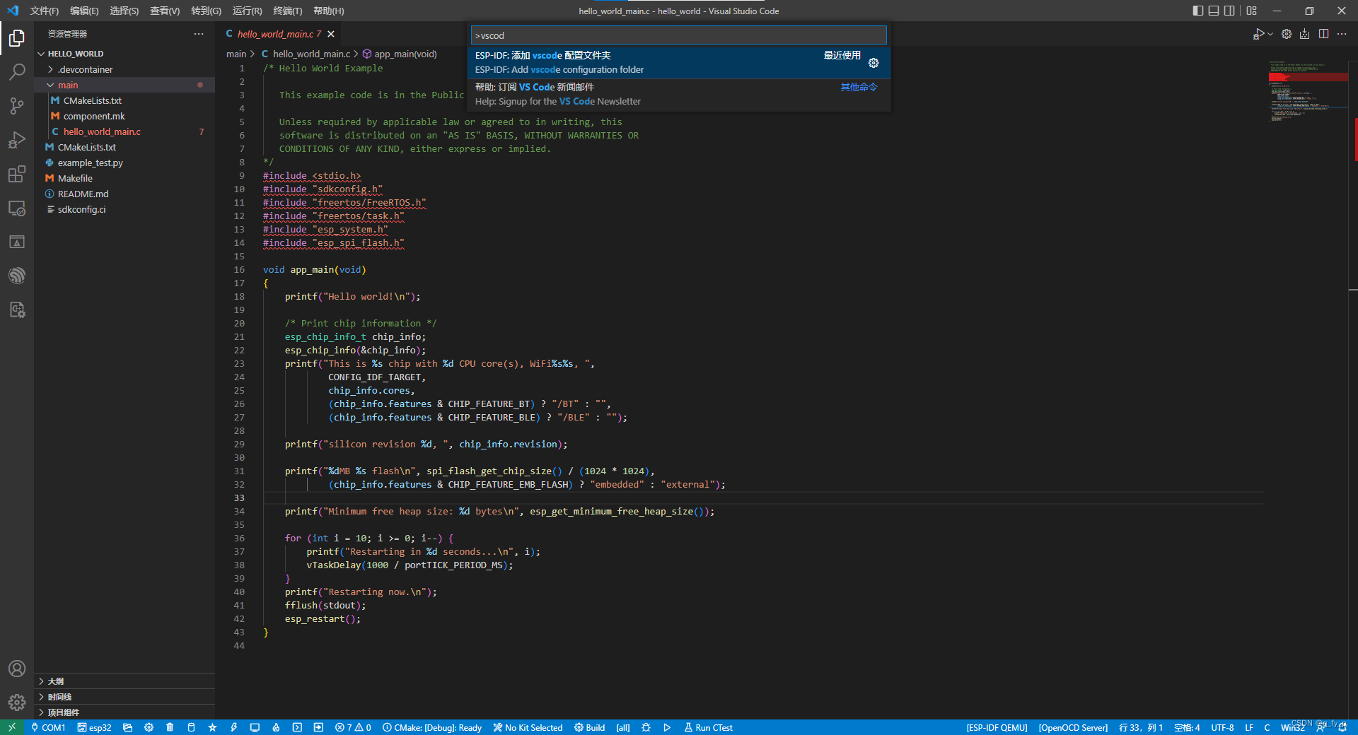
2.快捷键F1,输入vscode,选择 添加vscode配置文件夹


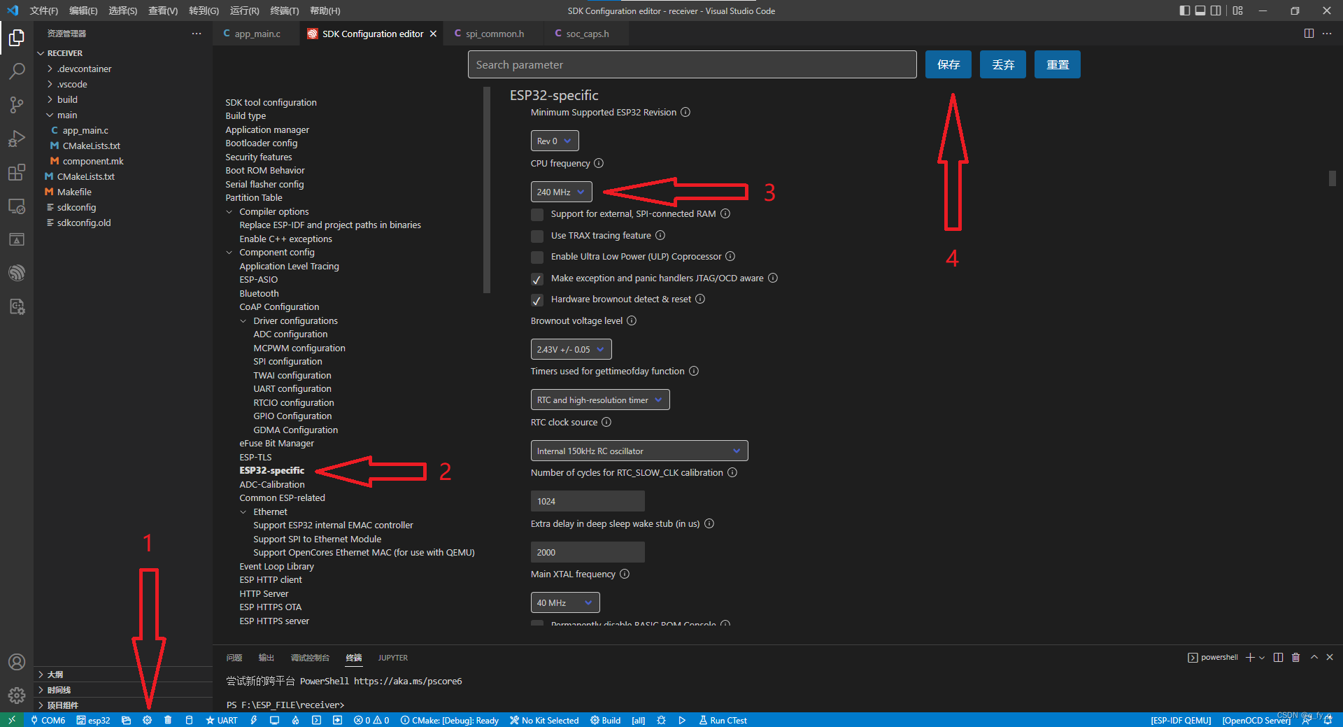
选择和ESP32连接的COM口,设置ESP32主频,编译下载 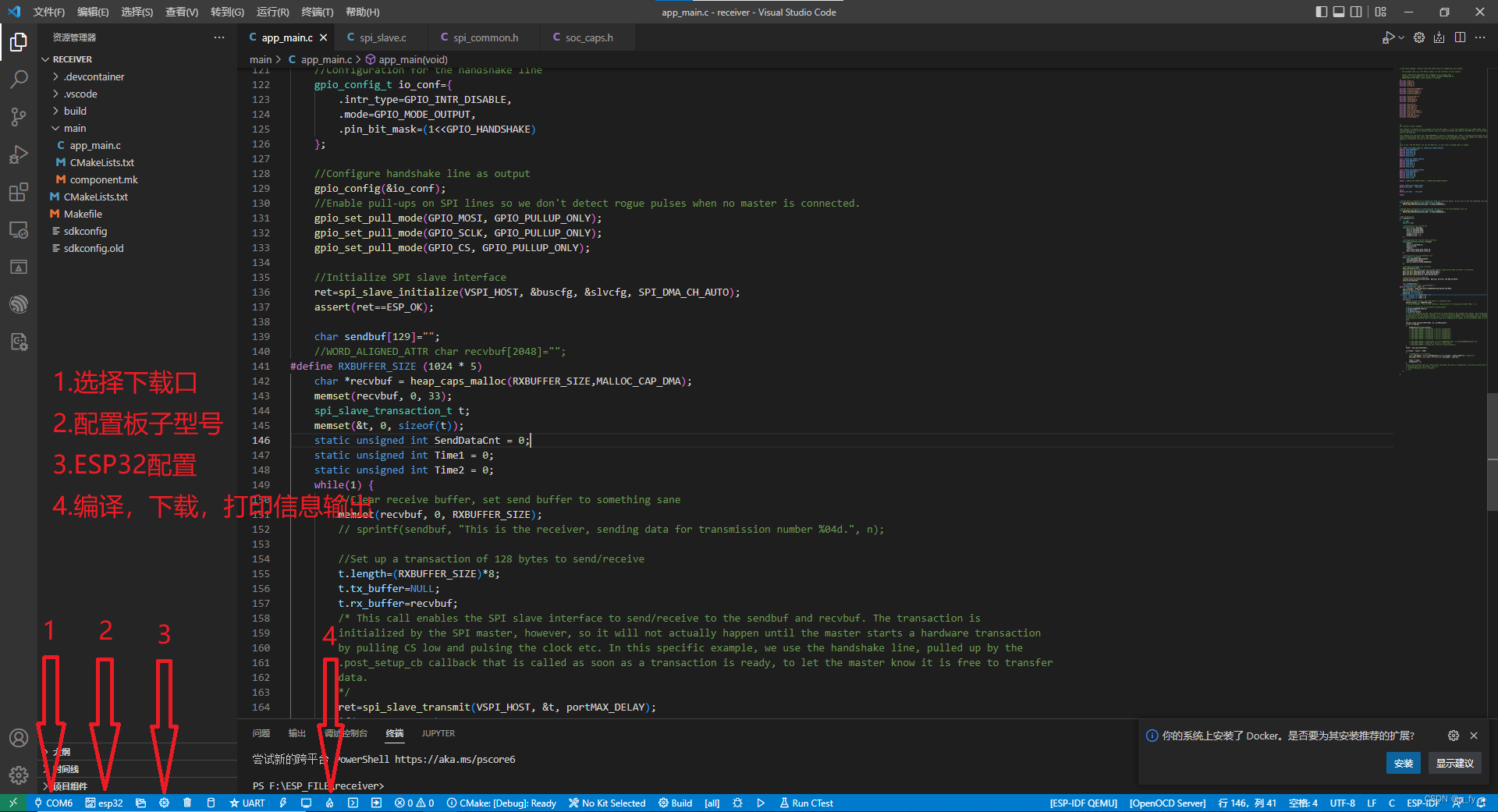
配置主频240MHz:
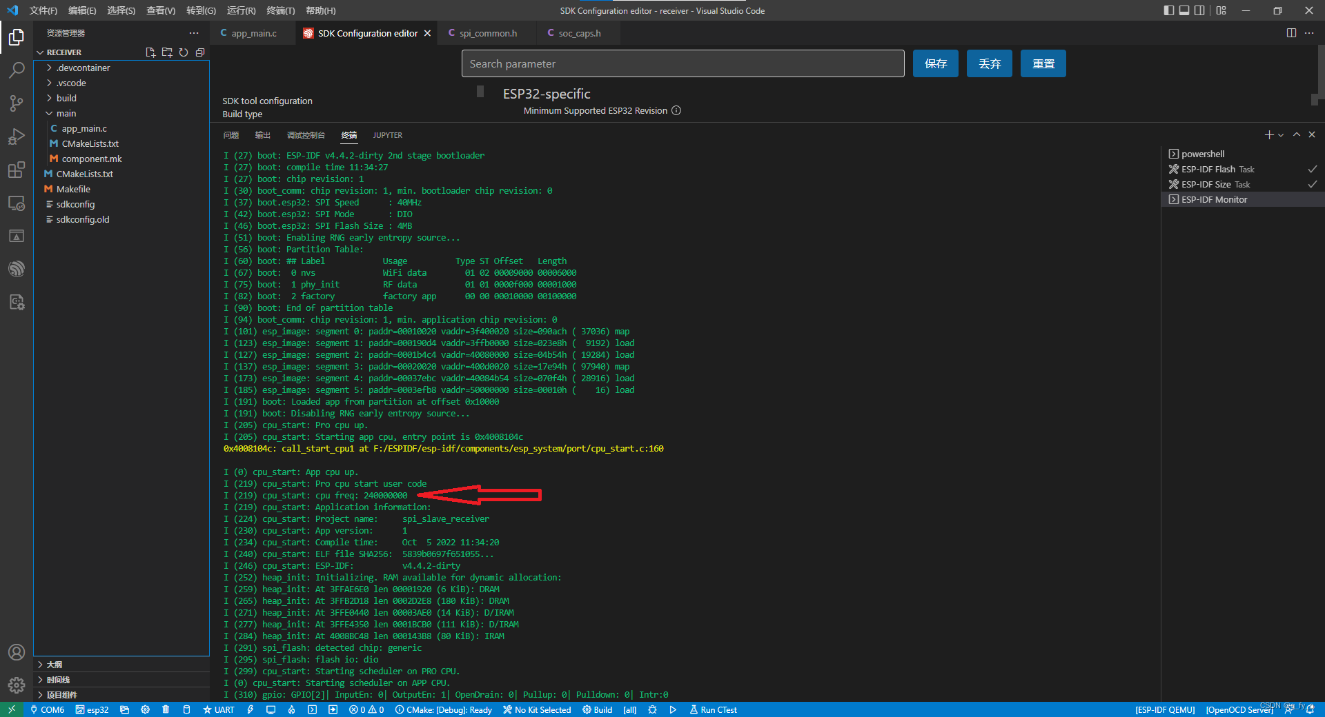
重新编译下载后:
(3)修改代码
ESP32端代码:再app_main.c中修改
/* SPI Slave example, receiver (uses SPI Slave driver to communicate with sender)
This example code is in the Public Domain (or CC0 licensed, at your option.)
Unless required by applicable law or agreed to in writing, this
software is distributed on an "AS IS" BASIS, WITHOUT WARRANTIES OR
CONDITIONS OF ANY KIND, either express or implied.
*/
#include <stdio.h>
#include <stdint.h>
#include <stddef.h>
#include <string.h>
#include "freertos/FreeRTOS.h"
#include "freertos/task.h"
#include "freertos/semphr.h"
#include "freertos/queue.h"
#include "lwip/sockets.h"
#include "lwip/dns.h"
#include "lwip/netdb.h"
#include "lwip/igmp.h"
#include "esp_wifi.h"
#include "esp_system.h"
#include "esp_event.h"
#include "nvs_flash.h"
#include "soc/rtc_periph.h"
#include "driver/spi_slave.h"
#include "esp_log.h"
#include "esp_spi_flash.h"
#include "driver/gpio.h"
/*
SPI receiver (slave) example.
This example is supposed to work together with the SPI sender. It uses the standard SPI pins (MISO, MOSI, SCLK, CS) to
transmit data over in a full-duplex fashion, that is, while the master puts data on the MOSI pin, the slave puts its own
data on the MISO pin.
This example uses one extra pin: GPIO_HANDSHAKE is used as a handshake pin. After a transmission has been set up and we're
ready to send/receive data, this code uses a callback to set the handshake pin high. The sender will detect this and start
sending a transaction. As soon as the transaction is done, the line gets set low again.
*/
/*
Pins in use. The SPI Master can use the GPIO mux, so feel free to change these if needed.
*/
#if CONFIG_IDF_TARGET_ESP32 || CONFIG_IDF_TARGET_ESP32S2
#define GPIO_HANDSHAKE 2
#define GPIO_MOSI 12
#define GPIO_MISO 13
#define GPIO_SCLK 15
#define GPIO_CS 14
#elif CONFIG_IDF_TARGET_ESP32C3
#define GPIO_HANDSHAKE 3
#define GPIO_MOSI 7
#define GPIO_MISO 2
#define GPIO_SCLK 6
#define GPIO_CS 10
#elif CONFIG_IDF_TARGET_ESP32S3
#define GPIO_HANDSHAKE 2
#define GPIO_MOSI 11
#define GPIO_MISO 13
#define GPIO_SCLK 12
#define GPIO_CS 10
#endif //CONFIG_IDF_TARGET_ESP32 || CONFIG_IDF_TARGET_ESP32S2
#ifdef CONFIG_IDF_TARGET_ESP32
#define RCV_HOST HSPI_HOST
#else
#define RCV_HOST SPI2_HOST
#endif
//Called after a transaction is queued and ready for pickup by master. We use this to set the handshake line high.
void my_post_setup_cb(spi_slave_transaction_t *trans) {
WRITE_PERI_REG(GPIO_OUT_W1TS_REG, (1<<GPIO_HANDSHAKE));
}
//Called after transaction is sent/received. We use this to set the handshake line low.
void my_post_trans_cb(spi_slave_transaction_t *trans) {
WRITE_PERI_REG(GPIO_OUT_W1TC_REG, (1<<GPIO_HANDSHAKE));
}
//Main application
void app_main(void)
{
int n=0;
esp_err_t ret;
//Configuration for the SPI bus
spi_bus_config_t buscfg={
.mosi_io_num=GPIO_MOSI,
.miso_io_num=GPIO_MISO,
.sclk_io_num=GPIO_SCLK,
.quadwp_io_num = -1,
.quadhd_io_num = -1,
};
//Configuration for the SPI slave interface
spi_slave_interface_config_t slvcfg={
.mode=0,
.spics_io_num=GPIO_CS,
.queue_size=3,
.flags=0,
.post_setup_cb=my_post_setup_cb,
.post_trans_cb=my_post_trans_cb
};
//Configuration for the handshake line
gpio_config_t io_conf={
.intr_type=GPIO_INTR_DISABLE,
.mode=GPIO_MODE_OUTPUT,
.pin_bit_mask=(1<<GPIO_HANDSHAKE)
};
//Configure handshake line as output
gpio_config(&io_conf);
//Enable pull-ups on SPI lines so we don't detect rogue pulses when no master is connected.
gpio_set_pull_mode(GPIO_MOSI, GPIO_PULLUP_ONLY);
gpio_set_pull_mode(GPIO_SCLK, GPIO_PULLUP_ONLY);
gpio_set_pull_mode(GPIO_CS, GPIO_PULLUP_ONLY);
//Initialize SPI slave interface
ret=spi_slave_initialize(VSPI_HOST, &buscfg, &slvcfg, SPI_DMA_CH_AUTO);
assert(ret==ESP_OK);
char sendbuf[129]="";
//WORD_ALIGNED_ATTR char recvbuf[2048]="";
#define RXBUFFER_SIZE (1024 * 2)
WORD_ALIGNED_ATTR char *recvbuf = heap_caps_malloc(RXBUFFER_SIZE,MALLOC_CAP_DMA);
memset(recvbuf, 0, 33);
spi_slave_transaction_t t;
memset(&t, 0, sizeof(t));
static unsigned int SendDataCnt = 0;
static unsigned int Time1 = 0;
static unsigned int Time2 = 0;
while(1) {
//Clear receive buffer, set send buffer to something sane
memset(recvbuf, 0, RXBUFFER_SIZE);
// sprintf(sendbuf, "This is the receiver, sending data for transmission number %04d.", n);
//Set up a transaction of 128 bytes to send/receive
t.length=(RXBUFFER_SIZE)*8;
t.tx_buffer=NULL;
t.rx_buffer=recvbuf;
/* This call enables the SPI slave interface to send/receive to the sendbuf and recvbuf. The transaction is
initialized by the SPI master, however, so it will not actually happen until the master starts a hardware transaction
by pulling CS low and pulsing the clock etc. In this specific example, we use the handshake line, pulled up by the
.post_setup_cb callback that is called as soon as a transaction is ready, to let the master know it is free to transfer
data.
*/
ret=spi_slave_transmit(VSPI_HOST, &t, portMAX_DELAY);
if(ret == ESP_OK)
{
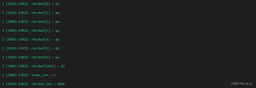
SendDataCnt+=strlen(recvbuf);
ESP_LOGI("ESP32","recvbuf[0] = %x\r\n",recvbuf[0]);
ESP_LOGI("ESP32","recvbuf[1] = %x\r\n",recvbuf[1]);
ESP_LOGI("ESP32","recvbuf[2] = %x\r\n",recvbuf[2]);
ESP_LOGI("ESP32","recvbuf[3] = %x\r\n",recvbuf[3]);
ESP_LOGI("ESP32","recvbuf[4] = %x\r\n",recvbuf[4]);
ESP_LOGI("ESP32","recvbuf[5] = %x\r\n",recvbuf[5]);
ESP_LOGI("ESP32","recvbuf[6] = %x\r\n",recvbuf[6]);
ESP_LOGI("ESP32","recvbuf[%d] = %x\r\n",RXBUFFER_SIZE - 1,recvbuf[RXBUFFER_SIZE -1]);
ESP_LOGI("ESP32","trans_len = %d\r\n",t.trans_len);
ESP_LOGI("ESP32","recvbuf_len = %d\r\n",strlen(recvbuf));
}
Time2 = esp_log_timestamp();
if((Time2 - Time1) > 1000)
{
//SendDataCnt /= 8;/*bytes*/
float TCP_Speed = ((float)SendDataCnt)/((float)(Time2 - Time1)/1000.0f); /*bytes/s*/
ESP_LOGI("ESP32","SPI speed = %f kb/s\r\n",TCP_Speed / 1024.0f);
Time1 = Time2;
SendDataCnt = 0;
}
//spi_slave_transmit does not return until the master has done a transmission, so by here we have sent our data and
//received data from the master. Print it.
// printf("Received: %s\n", recvbuf);
// n++;
}
}
对于接收缓冲区recvbuf,SDK的一个头文件限制了缓冲区大小:(4096 - 4)超出大小会报错,当我设置更大的区域时(1024 * 10),发送方(20MHz SPI速率)每次(CS拉低拉高一次)发送(1024 * 10的数据大小)时并不能完全接收,大约只有8000多,这里不知道是什么原因造成的
同时缓冲区需要四字节对齐
二、STM32端SPI配置:
SPI 配置模式0 SPI速率: 84 / 4 = 21MHz
// SPI3初始化
void SPI3_Init(void)
{
    GPIO_InitTypeDef GPIO_InitStructure;
    SPI_InitTypeDef SPI_InitStructure;

    RCC_AHB1PeriphClockCmd(RCC_AHB1Periph_GPIOA | RCC_AHB1Periph_GPIOB, ENABLE); //使能GPIOA GPIOB时钟
    RCC_APB1PeriphClockCmd(RCC_APB1Periph_SPI3, ENABLE);                         //使能SPI3时钟

    /*SPI_CS*/
    GPIO_InitStructure.GPIO_Pin = GPIO_Pin_15;         // PA15复用功能输出
    GPIO_InitStructure.GPIO_Mode = GPIO_Mode_OUT;      //复用功能
    GPIO_InitStructure.GPIO_OType = GPIO_OType_PP;     //推挽输出
    GPIO_InitStructure.GPIO_Speed = GPIO_Speed_100MHz; // 100MHz
    GPIO_InitStructure.GPIO_PuPd = GPIO_PuPd_NOPULL;   //上拉
    GPIO_Init(GPIOA, &GPIO_InitStructure);             //初始化

    /*SPI_HANDSHAKE*/
    GPIO_InitStructure.GPIO_Pin = GPIO_Pin_6;          // PB6复用功能输出
    GPIO_InitStructure.GPIO_Mode = GPIO_Mode_IN;       //复用功能
    GPIO_InitStructure.GPIO_OType = GPIO_OType_PP;     //推挽输出
    GPIO_InitStructure.GPIO_Speed = GPIO_Speed_100MHz; // 100MHz
    GPIO_InitStructure.GPIO_PuPd = GPIO_PuPd_NOPULL;   //上拉
    GPIO_Init(GPIOB, &GPIO_InitStructure);             //初始化

    // PB3 SPI_SCK PB4 SPI_MISO PB5 SPI_MOSI
    GPIO_InitStructure.GPIO_Pin = GPIO_Pin_3 | GPIO_Pin_4 | GPIO_Pin_5; // PB3~5复用功能输出
    GPIO_InitStructure.GPIO_Mode = GPIO_Mode_AF;                        //复用功能
    GPIO_InitStructure.GPIO_OType = GPIO_OType_PP;                      //推挽输出
    GPIO_InitStructure.GPIO_Speed = GPIO_Speed_100MHz;                  // 100MHz
    GPIO_InitStructure.GPIO_PuPd = GPIO_PuPd_UP;                        //上拉
    GPIO_Init(GPIOB, &GPIO_InitStructure);                              //初始化

    GPIO_PinAFConfig(GPIOB, GPIO_PinSource3, GPIO_AF_SPI3); // PB3复用为 SPI3
    GPIO_PinAFConfig(GPIOB, GPIO_PinSource4, GPIO_AF_SPI3); // PB4复用为 SPI3
    GPIO_PinAFConfig(GPIOB, GPIO_PinSource5, GPIO_AF_SPI3); // PB5复用为 SPI3

    //这里只针对SPI口初始化
    RCC_APB1PeriphResetCmd(RCC_APB1Periph_SPI3, ENABLE);  //复位SPI3
    RCC_APB1PeriphResetCmd(RCC_APB1Periph_SPI3, DISABLE); //停止复位SPI3

    SPI_InitStructure.SPI_Direction = SPI_Direction_2Lines_FullDuplex; //设置SPI单向或者双向的数据模式:SPI设置为双线双向全双工
    SPI_InitStructure.SPI_Mode = SPI_Mode_Master;                      //设置SPI工作模式:设置为主SPI
    SPI_InitStructure.SPI_DataSize = SPI_DataSize_8b;                  //设置SPI的数据大小:SPI发送接收8位帧结构
    SPI_InitStructure.SPI_CPOL = SPI_CPOL_Low;                         //串行同步时钟的空闲状态为高电平
    SPI_InitStructure.SPI_CPHA = SPI_CPHA_1Edge;                       //串行同步时钟的第二个跳变沿(上升或下降)数据被采样
    SPI_InitStructure.SPI_NSS = SPI_NSS_Soft;                          // NSS信号由硬件(NSS管脚)还是软件(使用SSI位)管理:内部NSS信号有SSI位控制
    SPI_InitStructure.SPI_BaudRatePrescaler = SPI_BaudRatePrescaler_4; //定义波特率预分频的值:波特率预分频值为256
    SPI_InitStructure.SPI_FirstBit = SPI_FirstBit_MSB;                 //指定数据传输从MSB位还是LSB位开始:数据传输从MSB位开始
    SPI_InitStructure.SPI_CRCPolynomial = 7;                           // CRC值计算的多项式
    SPI_Init(SPI3, &SPI_InitStructure);                                //根据SPI_InitStruct中指定的参数初始化外设SPIx寄存器

    // SPI_CalculateCRC(SPI3, DISABLE);		/*关闭SPI CRC校验*/

    SPI_ClearFlag(SPI3, SPI_FLAG_TXE);
    SPI_ClearFlag(SPI3, SPI_FLAG_RXNE); /*清除接收发送标志*/
    SPI_Cmd(SPI3, ENABLE);
}
// SPI3速度设置函数
// SPI速度=fAPB2/分频系数
//@ref SPI_BaudRate_Prescaler:SPI_BaudRatePrescaler_2~SPI_BaudRatePrescaler_256
// fAPB2时钟一般为84Mhz:
void SPI3_SetSpeed(unsigned char SPI_BaudRatePrescaler)
{
    assert_param(IS_SPI_BAUDRATE_PRESCALER(SPI_BaudRatePrescaler)); //判断有效性
    SPI3->CR1 &= 0XFFC7;                                            //位3-5清零,用来设置波特率
    SPI3->CR1 |= SPI_BaudRatePrescaler;                             //设置SPI3速度
    SPI_Cmd(SPI3, ENABLE);                                          //使能SPI3
}
// SPI3 读写一个字节
// TxData:要写入的字节
//返回值:读取到的字节
unsigned char SPI3_ReadWriteByte(unsigned char TxData)
{
    unsigned char SPI_RxData;

    while (SPI_I2S_GetFlagStatus(SPI3, SPI_I2S_FLAG_TXE) == RESET)
    {
    } //等待发送区空

    SPI_I2S_SendData(SPI3, TxData); //通过外设SPIx发送一个byte  数据

    while (SPI_I2S_GetFlagStatus(SPI3, SPI_I2S_FLAG_RXNE) == RESET)
    {
    } //等待接收完一个byte

    SPI_RxData = SPI_I2S_ReceiveData(SPI3); //返回通过SPIx最近接收的数据

    return SPI_RxData;
}
STM32端任务
#define SPI_BUFF_SIZE (1024 * 2)
unsigned char SPI_Buffer[SPI_BUFF_SIZE];
void LED_Task(void *pvParameters) /*系统指示灯,正常工作保持闪烁*/
{
    static unsigned int SPI_DataBufferLen = SPI_BUFF_SIZE;
    TickType_t PreviousWakeTime = xTaskGetTickCount();
    for (int i = 0; i < SPI_BUFF_SIZE; i++)
    {
        SPI_Buffer[i] = 0xAA;
    }
    while (1)
    {
        //		PreviousWakeTime = xTaskGetTickCount();

        if (GPIO_ReadInputDataBit(GPIOB, GPIO_Pin_6) == 1)
        {

            SPI_Buffer[0] = 0xA1;
            //			SPI_Buffer[1] = SPI_DataBufferLen;
            //			SPI_Buffer[2] = SPI_DataBufferLen>>8;
            //			SPI_Buffer[3] = SPI_DataBufferLen>>16;
            //			SPI_Buffer[4] = SPI_DataBufferLen>>24;
            SPI_Buffer[5] = 0xA2;
            SPI_Buffer[SPI_BUFF_SIZE - 1] = 0xA3;

            GPIO_ResetBits(GPIOA, GPIO_Pin_15);
            for (int i = 0; i < SPI_BUFF_SIZE; i++)
            {

                SPI3_ReadWriteByte(SPI_Buffer[i]);
            }
            GPIO_SetBits(GPIOA, GPIO_Pin_15);
            LED0 = ~LED0;
        }

        //		vTaskDelayUntil(&PreviousWakeTime, configTICK_RATE_HZ/10);
    }
}
其余按照引脚接线即可
三、通讯结果
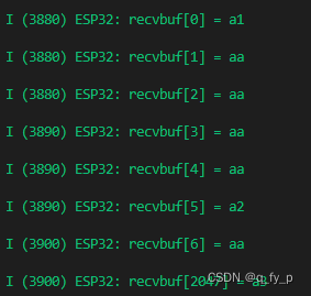
数据内容测试
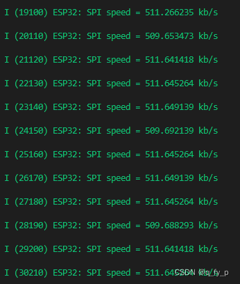
SPI速度测试
改变发送端发送数据大小,接收端缓冲区大小不变
发送端-> #define SPI_BUFF_SIZE (1024 * 2) 修改为-> #define SPI_BUFF_SIZE (1024 * 1)
打印速度:
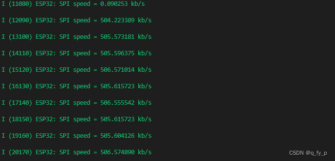
速度差距不是很大


 1353
1353

 被折叠的 条评论
为什么被折叠?
被折叠的 条评论
为什么被折叠?
 到【灌水乐园】发言


