


软件STM32cubeIDE下STM32F4xx使用32位定时器2(TIM2)用DMA+PWM点亮灯带WS2812-基础样例
(1)前言6
之前想使用STM32F4xx点亮灯带WS2812,在使用TIM2_ch1(PA0)点灯带2812的时候,发现按照网上资料或者查手册,都没办法点灯,同时测试了使用TIM3_ch1(PA6)的时候,发现能够正常点ws2812。这就奇怪了,同样的定时器,一个行一个就不行,一查才知道,F4上,tim2是32位的,tim3是16位的,就这点区别,但是多次尝试未果,后来问了大神吧,总算解决了,现在将这个问题解决办法记录下来,毕竟花我100RMB呢。
(2)环境
- 软件环境:STM32cubeIDE 1.8.0
- 硬件芯片:STM32F407ZGT6
- HAL库版本:stm32cube_fw_f4_v1262
(3)问题细节
具体问题细节,请看下边链接,当时想要解决这个问题,特意花了钱悬赏,但是并没有解决。
以下是链接:https://ask.csdn.net/questions/7589282
(4)解决思路
和自己的想法一样,可以说TIM2和TIM3唯一区别就是tim2是32位定时器,tim3是16位寄存器,使用的时候需要注意。
TIM2的CCR寄存器是32位宽的,而TIM3的CCR寄存器是16位宽的,所以在传输数据时,一定要注意配置的数据位宽和DMA的长度位宽要一致,TIM2的传输数据位宽推荐使用32位宽。
尤其是当配置为16位宽数据传输时,要确保传入寄存器的值要为16位宽,否则就没有波形输出。
(5)代码链接
以下是我本次使用代码,下面也会有代码说明,不想要代码,看看思路也能看明白的。
https://download.csdn.net/download/qq_22146161/72392551
(6)代码说明
(1)配置细节
如下图,是使用软件STM32cubeIDE配置出来的。
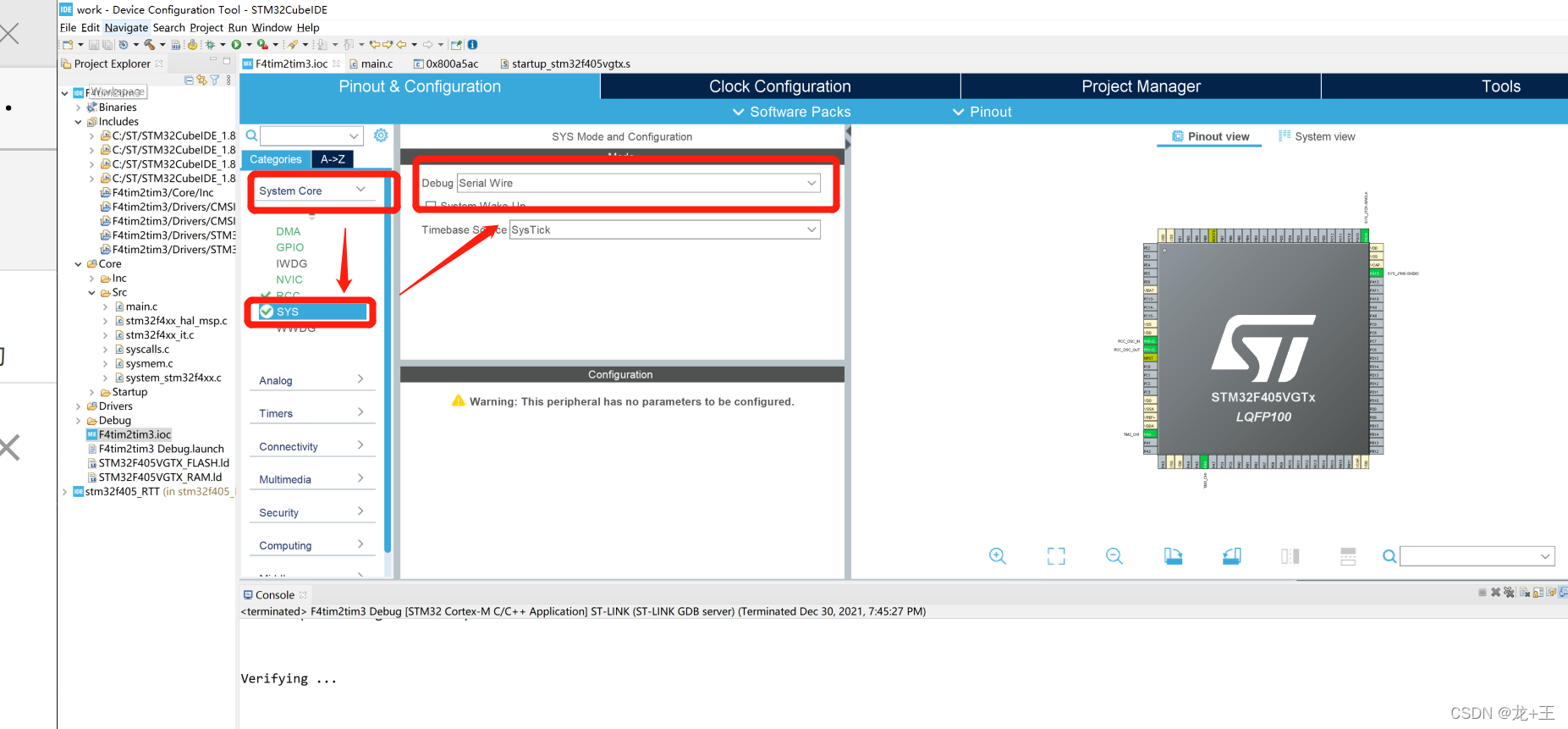
(1)调试部分-基础配置-没什么好说的,这样配就行,大家都一样
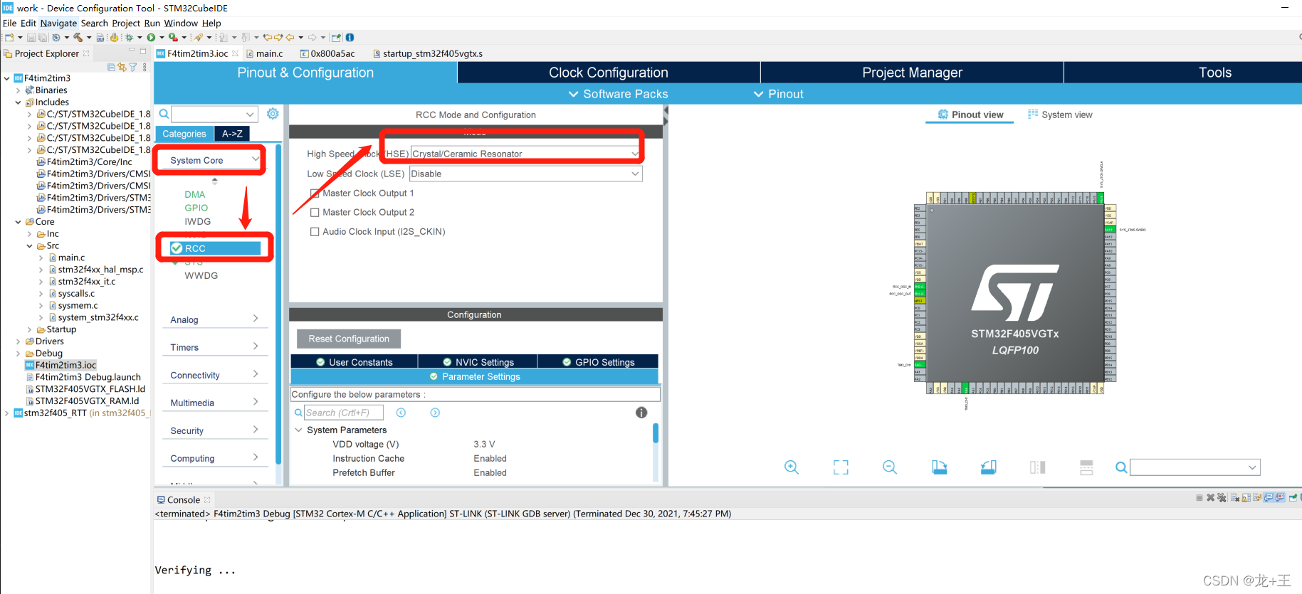
(2)时钟引脚配置-基础配置-没什么好说的,这样配就行,大家都一样
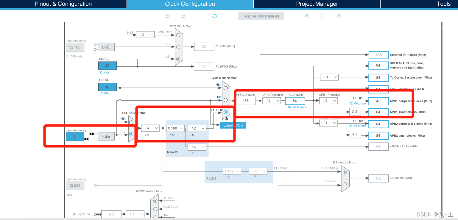
(3)时钟配置F4基本上系统时钟都168M,然后APB1 TImer clocks就是84M,这个时钟可以最后配置,但是定时器周期一定要105。
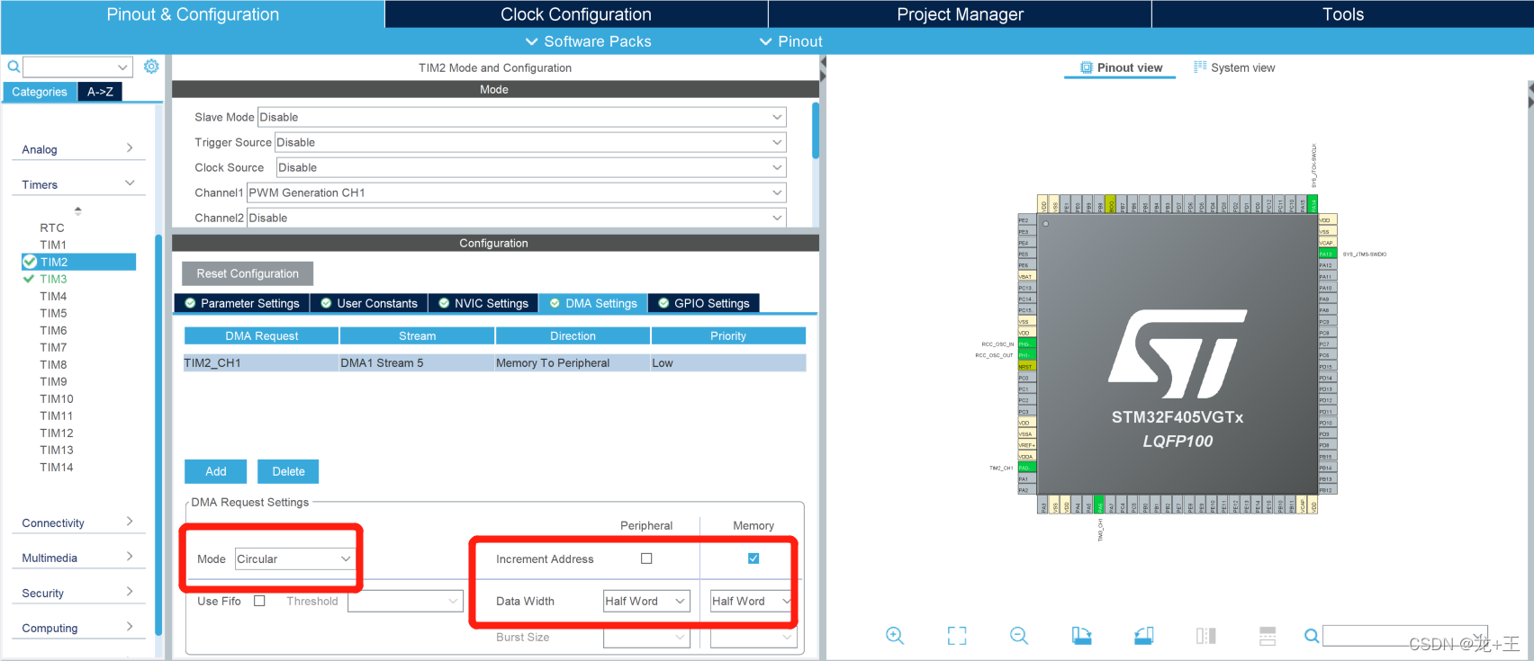
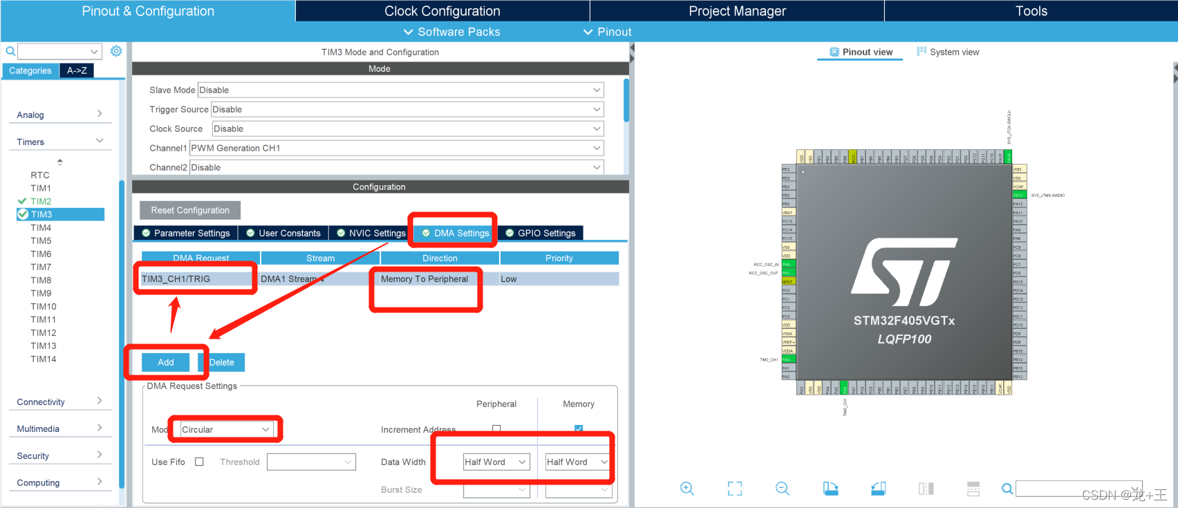
(4)定时器2配置,选择通道1,选择tim2_ch1,选择内存到外设,DMA模式选择循环模式
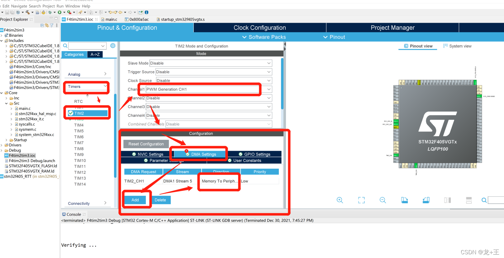
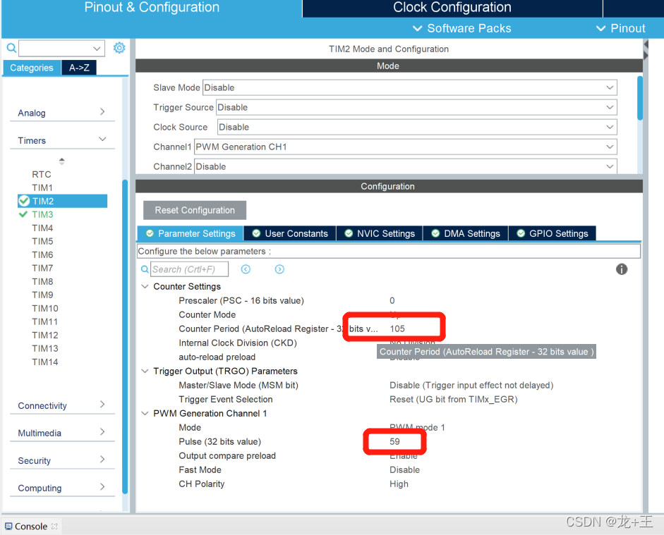
另外因为要点灯带ws2812,周期选择105,(为啥是105呐),因为WS2812这个灯带,需求周期位800khz,也就是1.25uS。84M/105=800khz.如下图。
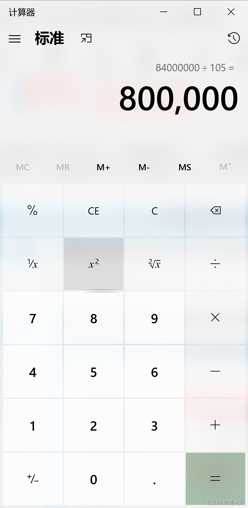
如下找到设置,输入105。
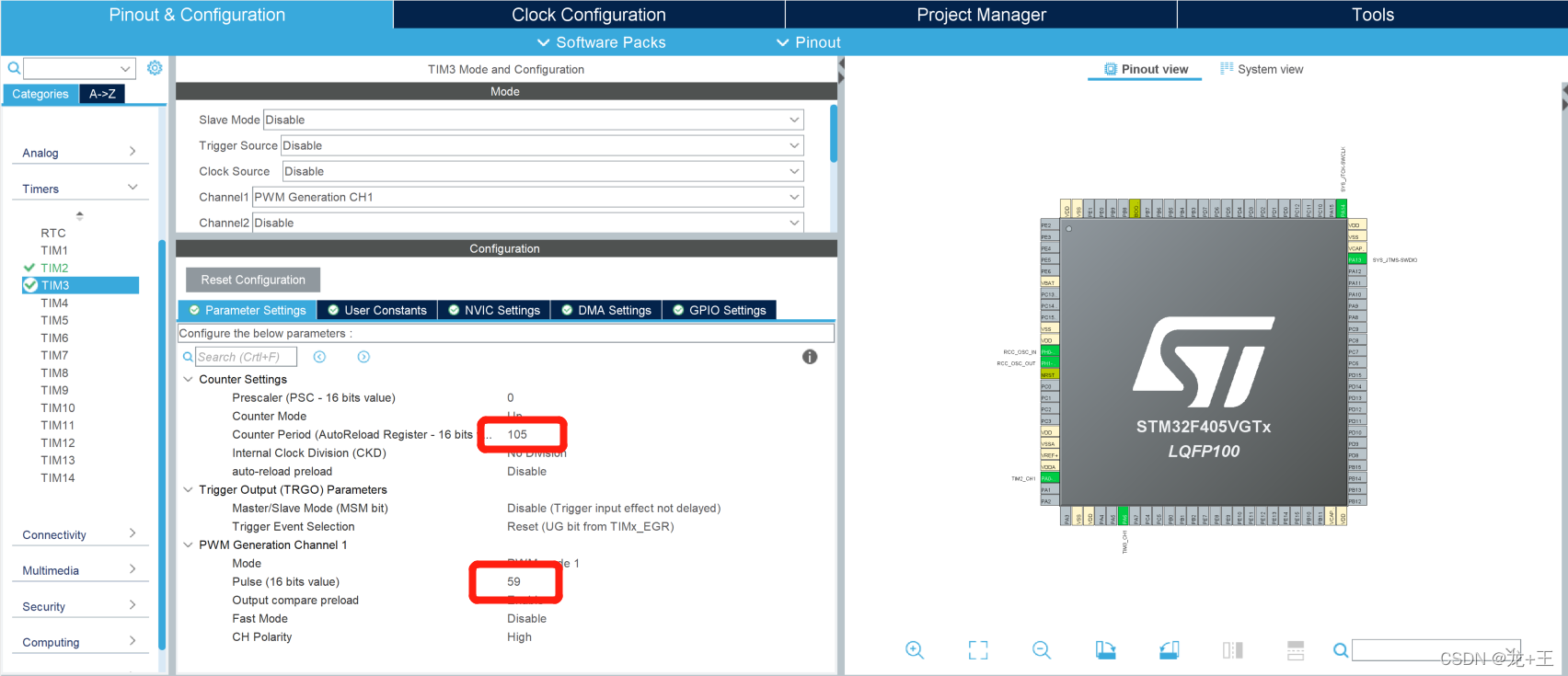
(5)定时器3配置雷同tim2配置。
别忘了开DMA通道,其它不用管。
(2)代码细节
(1)从代码函数的方面需要注意函数
注意:初始化部分函数,顺序不能颠倒,发现在移植过程中,因为初始化顺序,导致的很大问题。
- 初始化函数
MX_GPIO_Init(); - DMA初始化函数
MX_DMA_Init(); - 定时器初始化函数
MX_TIM2_Init();
MX_TIM3_Init();
前三个函数没啥好说的,只要注意顺不颠倒就行,配置好后,软件自动生成上边几个初始函数。
-
隐藏的配置函数
这个函数挺恼人的,它虽然不写出来,但是会默认执行,配置一旦初始化顺序不对,它就不好使,还不好找,而且不同软件版本可能还不一样。
void HAL_TIM_Base_MspInit(TIM_HandleTypeDef htim_base);*
或者
void HAL_TIM_PWM_MspInit(TIM_HandleTypeDef htim_pwm);*
上述两个函数,软件会帮咱们默认生成其中之一,都是DMA通道配置函数,但是它不在写出来,回调出来的。不在眼前容易看不到。 -
功能函数
因为要点功灯带WS2812,所以简单写了一个功能函数,如果你不点灯带也没关系,简单功能实现也会告诉你F4上TIM2和TIM3是有差别的,都在ws2812_example();内。
(1)想到点灯带,看看如何实现的
在功能函数内,ws2812_set_RGB和ws2812_set_RGB1两个函数是帮忙赛数据,再给tim2和tim3准备数据,使用HAl库准备好的函数HAL_TIM_PWM_Start_DMA发送数据。
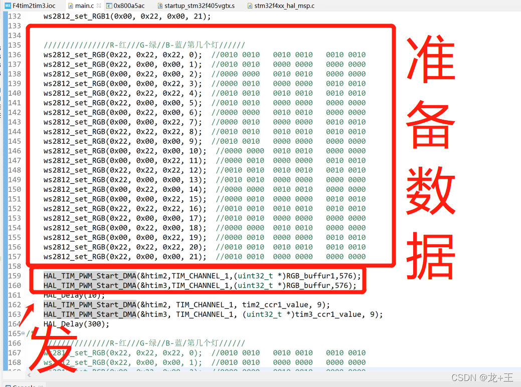
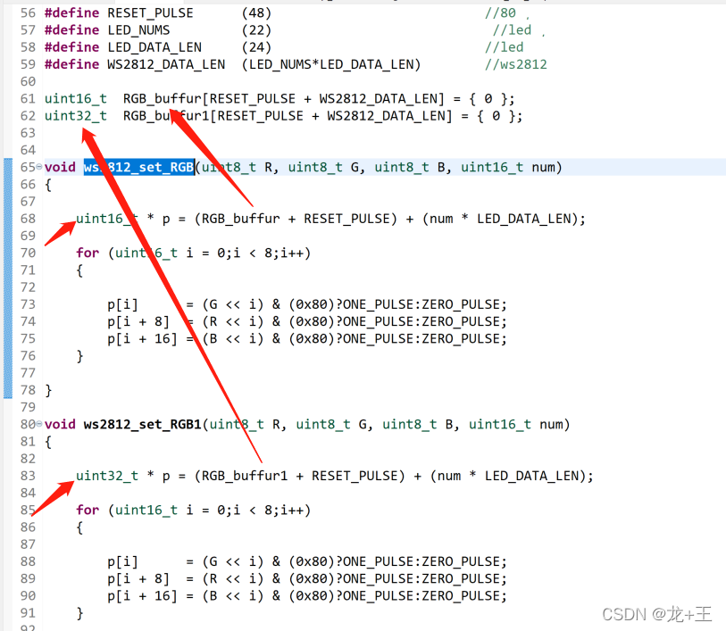
在使用函数ws2812_set_RGB和ws2812_set_RGB1塞数据的时候,注意,TIM2全程使用32位的,TIM3全程使用16位的
(2)不想点灯带,看看如何输出的
自己准备的数据,注意TIM2要uint32_t位的。TIM3要uint16_t位的。
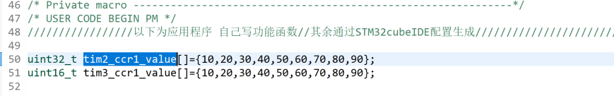
发送数据时,HAL_TIM_PWM_Start_DMA函数对于32位数据不需要强制转换,但是TIM3是16位的需要强转。

以下位代码段
main.c
/* USER CODE BEGIN Header */
/**
******************************************************************************
* @file : main.c
* @brief : Main program body
******************************************************************************
* @attention
*
* <h2><center>© Copyright (c) 2021 STMicroelectronics.
* All rights reserved.</center></h2>
*
* This software component is licensed by ST under BSD 3-Clause license,
* the "License"; You may not use this file except in compliance with the
* License. You may obtain a copy of the License at:
* opensource.org/licenses/BSD-3-Clause
*
******************************************************************************
*/
/* USER CODE END Header */
/* Includes ------------------------------------------------------------------*/
#include "main.h"
/* Private includes ----------------------------------------------------------*/
/* USER CODE BEGIN Includes */
/* USER CODE END Includes */
/* Private typedef -----------------------------------------------------------*/
/* USER CODE BEGIN PTD */
/* USER CODE END PTD */
/* Private define ------------------------------------------------------------*/
/* USER CODE BEGIN PD */
/* USER CODE END PD */
/* Private variables ---------------------------------------------------------*/
TIM_HandleTypeDef htim2;
TIM_HandleTypeDef htim3;
DMA_HandleTypeDef hdma_tim2_ch1;
DMA_HandleTypeDef hdma_tim3_ch1_trig;
/* USER CODE BEGIN PV */
/* Private macro -------------------------------------------------------------*/
/* USER CODE BEGIN PM */
/以下为应用程序 自己写功能函数//其余通过STM32cubeIDE配置生成
uint32_t tim2_ccr1_value[]={10,20,30,40,50,60,70,80,90};
uint16_t tim3_ccr1_value[]={10,20,30,40,50,60,70,80,90};
#define ONE_PULSE (59) //1
#define ZERO_PULSE (29) //0
#define RESET_PULSE (48) //80 ¸
#define LED_NUMS (22) //led ¸
#define LED_DATA_LEN (24) //led
#define WS2812_DATA_LEN (LED_NUMS*LED_DATA_LEN) //ws2812
uint16_t RGB_buffur[RESET_PULSE + WS2812_DATA_LEN] = { 0 };
uint32_t RGB_buffur1[RESET_PULSE + WS2812_DATA_LEN] = { 0 };
void ws2812_set_RGB(uint8_t R, uint8_t G, uint8_t B, uint16_t num)
{
uint16_t * p = (RGB_buffur + RESET_PULSE) + (num * LED_DATA_LEN);
for (uint16_t i = 0;i < 8;i++)
{
p[i] = (G << i) & (0x80)?ONE_PULSE:ZERO_PULSE;
p[i + 8] = (R << i) & (0x80)?ONE_PULSE:ZERO_PULSE;
p[i + 16] = (B << i) & (0x80)?ONE_PULSE:ZERO_PULSE;
}
}
void ws2812_set_RGB1(uint8_t R, uint8_t G, uint8_t B, uint16_t num)
{
uint32_t * p = (RGB_buffur1 + RESET_PULSE) + (num * LED_DATA_LEN);
for (uint16_t i = 0;i < 8;i++)
{
p[i] = (G << i) & (0x80)?ONE_PULSE:ZERO_PULSE;
p[i + 8] = (R << i) & (0x80)?ONE_PULSE:ZERO_PULSE;
p[i + 16] = (B << i) & (0x80)?ONE_PULSE:ZERO_PULSE;
}
}
void HAL_TIM_PWM_PulseFinishedCallback(TIM_HandleTypeDef *htim)
{
__HAL_TIM_SetCompare(htim, TIM_CHANNEL_1,0); //占空比清0,若不清会导致灯珠颜色不对
HAL_TIM_PWM_Stop_DMA(htim,TIM_CHANNEL_1);
// __HAL_TIM_SetCompare(htim, TIM_CHANNEL_2,0); //占空比清0,若不清会导致灯珠颜色不对
// HAL_TIM_PWM_Stop_DMA(htim,TIM_CHANNEL_2);
}
void ws2812_example(void)
{
ws2812_set_RGB1(0x22, 0x00, 0x00, 0);
ws2812_set_RGB1(0x00, 0x22, 0x00, 1);
ws2812_set_RGB1(0x00, 0x00, 0x22, 2);
ws2812_set_RGB1(0x22, 0x22, 0x22, 3);
ws2812_set_RGB1(0x22, 0x00, 0x00, 4);
ws2812_set_RGB1(0x00, 0x22, 0x00, 5);
ws2812_set_RGB1(0x00, 0x00, 0x22, 6);
ws2812_set_RGB1(0x22, 0x22, 0x22, 7);
ws2812_set_RGB1(0x22, 0x00, 0x00, 8);
ws2812_set_RGB1(0x00, 0x22, 0x00, 9);
ws2812_set_RGB1(0x00, 0x00, 0x22, 10);
ws2812_set_RGB1(0x22, 0x22, 0x22, 11);
ws2812_set_RGB1(0x22, 0x00, 0x00, 12);
ws2812_set_RGB1(0x00, 0x22, 0x00, 13);
ws2812_set_RGB1(0x00, 0x00, 0x22, 14);
ws2812_set_RGB1(0x22, 0x22, 0x22, 15);
ws2812_set_RGB1(0x22, 0x00, 0x00, 16);
ws2812_set_RGB1(0x00, 0x22, 0x00, 17);
ws2812_set_RGB1(0x00, 0x00, 0x22, 18);
ws2812_set_RGB1(0x22, 0x22, 0x22, 19);
ws2812_set_RGB1(0x22, 0x00, 0x00, 20);
ws2812_set_RGB1(0x00, 0x22, 0x00, 21);
///R-红///G-绿//B-蓝/第几个灯//
ws2812_set_RGB(0x22, 0x22, 0x22, 0); //0010 0010 0010 0010 0010 0010
ws2812_set_RGB(0x22, 0x00, 0x00, 1); //0010 0010 0000 0000 0000 0000
ws2812_set_RGB(0x00, 0x22, 0x00, 2); //0000 0000 0010 0010 0000 0000
ws2812_set_RGB(0x00, 0x00, 0x22, 3); //0000 0010 0000 0000 0010 0010
ws2812_set_RGB(0x22, 0x22, 0x22, 4); //0010 0010 0010 0010 0010 0010
ws2812_set_RGB(0x22, 0x00, 0x00, 5); //0010 0010 0000 0000 0000 0000
ws2812_set_RGB(0x00, 0x22, 0x00, 6); //0000 0000 0010 0010 0000 0000
ws2812_set_RGB(0x00, 0x00, 0x22, 7); //0000 0010 0000 0000 0010 0010
ws2812_set_RGB(0x22, 0x22, 0x22, 8); //0010 0010 0010 0010 0010 0010
ws2812_set_RGB(0x22, 0x00, 0x00, 9); //0010 0010 0000 0000 0000 0000
ws2812_set_RGB(0x00, 0x22, 0x00, 10); //0000 0000 0010 0010 0000 0000
ws2812_set_RGB(0x00, 0x00, 0x22, 11); //0000 0010 0000 0000 0010 0010
ws2812_set_RGB(0x22, 0x22, 0x22, 12); //0010 0010 0010 0010 0010 0010
ws2812_set_RGB(0x22, 0x00, 0x00, 13); //0010 0010 0000 0000 0000 0000
ws2812_set_RGB(0x00, 0x22, 0x00, 14); //0000 0000 0010 0010 0000 0000
ws2812_set_RGB(0x00, 0x00, 0x22, 15); //0000 0010 0000 0000 0010 0010
ws2812_set_RGB(0x22, 0x22, 0x22, 16); //0010 0010 0010 0010 0010 0010
ws2812_set_RGB(0x22, 0x00, 0x00, 17); //0010 0010 0000 0000 0000 0000
ws2812_set_RGB(0x00, 0x22, 0x00, 18); //0000 0000 0010 0010 0000 0000
ws2812_set_RGB(0x00, 0x00, 0x22, 19); //0000 0010 0000 0000 0010 0010
ws2812_set_RGB(0x22, 0x22, 0x22, 20); //0010 0010 0010 0010 0010 0010
ws2812_set_RGB(0x22, 0x00, 0x00, 21); //0010 0010 0000 0000 0000 0000
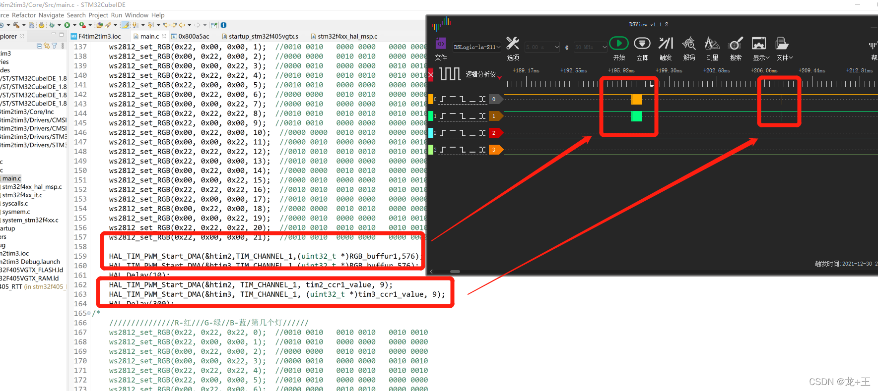
HAL_TIM_PWM_Start_DMA(&htim2,TIM_CHANNEL_1,(uint32_t *)RGB_buffur1,576);
HAL_TIM_PWM_Start_DMA(&htim3,TIM_CHANNEL_1,(uint32_t *)RGB_buffur,576);
HAL_Delay(10);
HAL_TIM_PWM_Start_DMA(&htim2, TIM_CHANNEL_1, tim2_ccr1_value, 9);
HAL_TIM_PWM_Start_DMA(&htim3, TIM_CHANNEL_1, (uint32_t *)tim3_ccr1_value, 9);
HAL_Delay(300);
/*
///R-红///G-绿//B-蓝/第几个灯//
ws2812_set_RGB(0x22, 0x22, 0x22, 0); //0010 0010 0010 0010 0010 0010
ws2812_set_RGB(0x22, 0x00, 0x00, 1); //0010 0010 0000 0000 0000 0000
ws2812_set_RGB(0x00, 0x22, 0x00, 2); //0000 0000 0010 0010 0000 0000
ws2812_set_RGB(0x00, 0x00, 0x22, 3); //0000 0010 0000 0000 0010 0010
ws2812_set_RGB(0x22, 0x22, 0x22, 4); //0010 0010 0010 0010 0010 0010
ws2812_set_RGB(0x22, 0x00, 0x00, 5); //0010 0010 0000 0000 0000 0000
ws2812_set_RGB(0x00, 0x22, 0x00, 6); //0000 0000 0010 0010 0000 0000
ws2812_set_RGB(0x00, 0x00, 0x22, 7); //0000 0010 0000 0000 0010 0010
ws2812_set_RGB(0x22, 0x22, 0x22, 8); //0010 0010 0010 0010 0010 0010
ws2812_set_RGB(0x22, 0x00, 0x00, 9); //0010 0010 0000 0000 0000 0000
ws2812_set_RGB(0x00, 0x22, 0x00, 10); //0000 0000 0010 0010 0000 0000
ws2812_set_RGB(0x00, 0x00, 0x22, 11); //0000 0010 0000 0000 0010 0010
ws2812_set_RGB(0x22, 0x22, 0x22, 12); //0010 0010 0010 0010 0010 0010
ws2812_set_RGB(0x22, 0x00, 0x00, 13); //0010 0010 0000 0000 0000 0000
ws2812_set_RGB(0x00, 0x22, 0x00, 14); //0000 0000 0010 0010 0000 0000
ws2812_set_RGB(0x00, 0x00, 0x22, 15); //0000 0010 0000 0000 0010 0010
ws2812_set_RGB(0x22, 0x22, 0x22, 16); //0010 0010 0010 0010 0010 0010
ws2812_set_RGB(0x22, 0x00, 0x00, 17); //0010 0010 0000 0000 0000 0000
ws2812_set_RGB(0x00, 0x22, 0x00, 18); //0000 0000 0010 0010 0000 0000
ws2812_set_RGB(0x00, 0x00, 0x22, 19); //0000 0010 0000 0000 0010 0010
ws2812_set_RGB(0x22, 0x22, 0x22, 20); //0010 0010 0010 0010 0010 0010
ws2812_set_RGB(0x22, 0x00, 0x00, 21); //0010 0010 0000 0000 0000 0000
//发送
HAL_TIM_PWM_Start_DMA(&htim2,TIM_CHANNEL_1,(uint32_t *)RGB_buffur,576);
HAL_TIM_PWM_Start_DMA(&htim3,TIM_CHANNEL_1,(uint32_t *)RGB_buffur,576);
HAL_Delay(100);
HAL_TIM_PWM_Start_DMA(&htim2, TIM_CHANNEL_1, tim2_ccr1_value, 9);
HAL_TIM_PWM_Start_DMA(&htim3, TIM_CHANNEL_1, (uint32_t *)tim3_ccr1_value, 9);
HAL_Delay(300);
*/
}
/以上为应用程序结束 自己写功能函数//其余通过STM32cubeIDE配置生成
/* USER CODE END PM */
/* USER CODE END PV */
/* Private function prototypes -----------------------------------------------*/
void SystemClock_Config(void);
static void MX_GPIO_Init(void);
static void MX_DMA_Init(void);
static void MX_TIM2_Init(void);
static void MX_TIM3_Init(void);
/* USER CODE BEGIN PFP */
/* USER CODE END PFP */
/* Private user code ---------------------------------------------------------*/
/* USER CODE BEGIN 0 */
/* USER CODE END 0 */
/**
* @brief The application entry point.
* @retval int
*/
int main(void)
{
/* USER CODE BEGIN 1 */
/* USER CODE END 1 */
/* MCU Configuration--------------------------------------------------------*/
/* Reset of all peripherals, Initializes the Flash interface and the Systick. */
HAL_Init();
/* USER CODE BEGIN Init */
/* USER CODE END Init */
/* Configure the system clock */
SystemClock_Config();
/* USER CODE BEGIN SysInit */
/* USER CODE END SysInit */
/* Initialize all configured peripherals */
MX_GPIO_Init();
MX_DMA_Init();
MX_TIM2_Init();
MX_TIM3_Init();
/* USER CODE BEGIN 2 */
/* USER CODE END 2 */
/* Infinite loop */
/* USER CODE BEGIN WHILE */
while (1)
{
/* USER CODE END WHILE */
ws2812_example();
// HAL_Delay(500);
// ws2812_example();
/* USER CODE BEGIN 3 */
}
/* USER CODE END 3 */
}
/**
* @brief System Clock Configuration
* @retval None
*/
void SystemClock_Config(void)
{
RCC_OscInitTypeDef RCC_OscInitStruct = {0};
RCC_ClkInitTypeDef RCC_ClkInitStruct = {0};
/** Configure the main internal regulator output voltage
*/
__HAL_RCC_PWR_CLK_ENABLE();
__HAL_PWR_VOLTAGESCALING_CONFIG(PWR_REGULATOR_VOLTAGE_SCALE1);
/** Initializes the RCC Oscillators according to the specified parameters
* in the RCC_OscInitTypeDef structure.
*/
RCC_OscInitStruct.OscillatorType = RCC_OSCILLATORTYPE_HSE;
RCC_OscInitStruct.HSEState = RCC_HSE_ON;
RCC_OscInitStruct.PLL.PLLState = RCC_PLL_ON;
RCC_OscInitStruct.PLL.PLLSource = RCC_PLLSOURCE_HSE;
RCC_OscInitStruct.PLL.PLLM = 4;
RCC_OscInitStruct.PLL.PLLN = 168;
RCC_OscInitStruct.PLL.PLLP = RCC_PLLP_DIV2;
RCC_OscInitStruct.PLL.PLLQ = 4;
if (HAL_RCC_OscConfig(&RCC_OscInitStruct) != HAL_OK)
{
Error_Handler();
}
/** Initializes the CPU, AHB and APB buses clocks
*/
RCC_ClkInitStruct.ClockType = RCC_CLOCKTYPE_HCLK|RCC_CLOCKTYPE_SYSCLK
|RCC_CLOCKTYPE_PCLK1|RCC_CLOCKTYPE_PCLK2;
RCC_ClkInitStruct.SYSCLKSource = RCC_SYSCLKSOURCE_PLLCLK;
RCC_ClkInitStruct.AHBCLKDivider = RCC_SYSCLK_DIV2;
RCC_ClkInitStruct.APB1CLKDivider = RCC_HCLK_DIV2;
RCC_ClkInitStruct.APB2CLKDivider = RCC_HCLK_DIV1;
if (HAL_RCC_ClockConfig(&RCC_ClkInitStruct, FLASH_LATENCY_2) != HAL_OK)
{
Error_Handler();
}
}
/**
* @brief TIM2 Initialization Function
* @param None
* @retval None
*/
static void MX_TIM2_Init(void)
{
/* USER CODE BEGIN TIM2_Init 0 */
/* USER CODE END TIM2_Init 0 */
TIM_ClockConfigTypeDef sClockSourceConfig = {0};
TIM_MasterConfigTypeDef sMasterConfig = {0};
TIM_OC_InitTypeDef sConfigOC = {0};
/* USER CODE BEGIN TIM2_Init 1 */
/* USER CODE END TIM2_Init 1 */
htim2.Instance = TIM2;
htim2.Init.Prescaler = 0;
htim2.Init.CounterMode = TIM_COUNTERMODE_UP;
htim2.Init.Period = 105;
htim2.Init.ClockDivision = TIM_CLOCKDIVISION_DIV1;
htim2.Init.AutoReloadPreload = TIM_AUTORELOAD_PRELOAD_ENABLE;
if (HAL_TIM_Base_Init(&htim2) != HAL_OK)
{
Error_Handler();
}
sClockSourceConfig.ClockSource = TIM_CLOCKSOURCE_INTERNAL;
if (HAL_TIM_ConfigClockSource(&htim2, &sClockSourceConfig) != HAL_OK)
{
Error_Handler();
}
if (HAL_TIM_PWM_Init(&htim2) != HAL_OK)
{
Error_Handler();
}
sMasterConfig.MasterOutputTrigger = TIM_TRGO_RESET;
sMasterConfig.MasterSlaveMode = TIM_MASTERSLAVEMODE_DISABLE;
if (HAL_TIMEx_MasterConfigSynchronization(&htim2, &sMasterConfig) != HAL_OK)
{
Error_Handler();
}
sConfigOC.OCMode = TIM_OCMODE_PWM1;
sConfigOC.Pulse = 59;
sConfigOC.OCPolarity = TIM_OCPOLARITY_HIGH;
sConfigOC.OCFastMode = TIM_OCFAST_ENABLE;
if (HAL_TIM_PWM_ConfigChannel(&htim2, &sConfigOC, TIM_CHANNEL_1) != HAL_OK)
{
Error_Handler();
}
/* USER CODE BEGIN TIM2_Init 2 */
/* USER CODE END TIM2_Init 2 */
HAL_TIM_MspPostInit(&htim2);
}
/**
* @brief TIM3 Initialization Function
* @param None
* @retval None
*/
static void MX_TIM3_Init(void)
{
/* USER CODE BEGIN TIM3_Init 0 */
/* USER CODE END TIM3_Init 0 */
TIM_ClockConfigTypeDef sClockSourceConfig = {0};
TIM_MasterConfigTypeDef sMasterConfig = {0};
TIM_OC_InitTypeDef sConfigOC = {0};
/* USER CODE BEGIN TIM3_Init 1 */
/* USER CODE END TIM3_Init 1 */
htim3.Instance = TIM3;
htim3.Init.Prescaler = 0;
htim3.Init.CounterMode = TIM_COUNTERMODE_UP;
htim3.Init.Period = 105;
htim3.Init.ClockDivision = TIM_CLOCKDIVISION_DIV1;
htim3.Init.AutoReloadPreload = TIM_AUTORELOAD_PRELOAD_ENABLE;
if (HAL_TIM_Base_Init(&htim3) != HAL_OK)
{
Error_Handler();
}
sClockSourceConfig.ClockSource = TIM_CLOCKSOURCE_INTERNAL;
if (HAL_TIM_ConfigClockSource(&htim3, &sClockSourceConfig) != HAL_OK)
{
Error_Handler();
}
if (HAL_TIM_PWM_Init(&htim3) != HAL_OK)
{
Error_Handler();
}
sMasterConfig.MasterOutputTrigger = TIM_TRGO_RESET;
sMasterConfig.MasterSlaveMode = TIM_MASTERSLAVEMODE_DISABLE;
if (HAL_TIMEx_MasterConfigSynchronization(&htim3, &sMasterConfig) != HAL_OK)
{
Error_Handler();
}
sConfigOC.OCMode = TIM_OCMODE_PWM1;
sConfigOC.Pulse = 59;
sConfigOC.OCPolarity = TIM_OCPOLARITY_HIGH;
sConfigOC.OCFastMode = TIM_OCFAST_ENABLE;
if (HAL_TIM_PWM_ConfigChannel(&htim3, &sConfigOC, TIM_CHANNEL_1) != HAL_OK)
{
Error_Handler();
}
/* USER CODE BEGIN TIM3_Init 2 */
/* USER CODE END TIM3_Init 2 */
HAL_TIM_MspPostInit(&htim3);
}
/**
* Enable DMA controller clock
*/
static void MX_DMA_Init(void)
{
/* DMA controller clock enable */
__HAL_RCC_DMA1_CLK_ENABLE();
/* DMA interrupt init */
/* DMA1_Stream4_IRQn interrupt configuration */
HAL_NVIC_SetPriority(DMA1_Stream4_IRQn, 0, 0);
HAL_NVIC_EnableIRQ(DMA1_Stream4_IRQn);
/* DMA1_Stream5_IRQn interrupt configuration */
HAL_NVIC_SetPriority(DMA1_Stream5_IRQn, 0, 0);
HAL_NVIC_EnableIRQ(DMA1_Stream5_IRQn);
}
/**
* @brief GPIO Initialization Function
* @param None
* @retval None
*/
static void MX_GPIO_Init(void)
{
/* GPIO Ports Clock Enable */
__HAL_RCC_GPIOH_CLK_ENABLE();
__HAL_RCC_GPIOA_CLK_ENABLE();
}
/* USER CODE BEGIN 4 */
/* USER CODE END 4 */
/**
* @brief This function is executed in case of error occurrence.
* @retval None
*/
void Error_Handler(void)
{
/* USER CODE BEGIN Error_Handler_Debug */
/* User can add his own implementation to report the HAL error return state */
__disable_irq();
while (1)
{
}
/* USER CODE END Error_Handler_Debug */
}
#ifdef USE_FULL_ASSERT
/**
* @brief Reports the name of the source file and the source line number
* where the assert_param error has occurred.
* @param file: pointer to the source file name
* @param line: assert_param error line source number
* @retval None
*/
void assert_failed(uint8_t *file, uint32_t line)
{
/* USER CODE BEGIN 6 */
/* User can add his own implementation to report the file name and line number,
ex: printf("Wrong parameters value: file %s on line %d\r\n", file, line) */
/* USER CODE END 6 */
}
#endif /* USE_FULL_ASSERT */
/************************ (C) COPYRIGHT STMicroelectronics *****END OF FILE****/
stm32f4xx_hal_msp.c
/* USER CODE BEGIN Header */
/**
******************************************************************************
* @file stm32f4xx_hal_msp.c
* @brief This file provides code for the MSP Initialization
* and de-Initialization codes.
******************************************************************************
* @attention
*
* <h2><center>© Copyright (c) 2021 STMicroelectronics.
* All rights reserved.</center></h2>
*
* This software component is licensed by ST under BSD 3-Clause license,
* the "License"; You may not use this file except in compliance with the
* License. You may obtain a copy of the License at:
* opensource.org/licenses/BSD-3-Clause
*
******************************************************************************
*/
/* USER CODE END Header */
/* Includes ------------------------------------------------------------------*/
#include "main.h"
/* USER CODE BEGIN Includes */
/* USER CODE END Includes */
extern DMA_HandleTypeDef hdma_tim2_ch1;
extern DMA_HandleTypeDef hdma_tim3_ch1_trig;
/* Private typedef -----------------------------------------------------------*/
/* USER CODE BEGIN TD */
/* USER CODE END TD */
/* Private define ------------------------------------------------------------*/
/* USER CODE BEGIN Define */
/* USER CODE END Define */
/* Private macro -------------------------------------------------------------*/
/* USER CODE BEGIN Macro */
/* USER CODE END Macro */
/* Private variables ---------------------------------------------------------*/
/* USER CODE BEGIN PV */
/* USER CODE END PV */
/* Private function prototypes -----------------------------------------------*/
/* USER CODE BEGIN PFP */
/* USER CODE END PFP */
/* External functions --------------------------------------------------------*/
/* USER CODE BEGIN ExternalFunctions */
/* USER CODE END ExternalFunctions */
/* USER CODE BEGIN 0 */
/* USER CODE END 0 */
void HAL_TIM_MspPostInit(TIM_HandleTypeDef *htim);
/**
* Initializes the Global MSP.
*/
void HAL_MspInit(void)
{
/* USER CODE BEGIN MspInit 0 */
/* USER CODE END MspInit 0 */
__HAL_RCC_SYSCFG_CLK_ENABLE();
__HAL_RCC_PWR_CLK_ENABLE();
/* System interrupt init*/
/* USER CODE BEGIN MspInit 1 */
/* USER CODE END MspInit 1 */
}
/**
* @brief TIM_Base MSP Initialization
* This function configures the hardware resources used in this example
* @param htim_base: TIM_Base handle pointer
* @retval None
*/
void HAL_TIM_Base_MspInit(TIM_HandleTypeDef* htim_base)
{
if(htim_base->Instance==TIM2)
{
/* USER CODE BEGIN TIM2_MspInit 0 */
/* USER CODE END TIM2_MspInit 0 */
/* Peripheral clock enable */
__HAL_RCC_TIM2_CLK_ENABLE();
/* TIM2 DMA Init */
/* TIM2_CH1 Init */
hdma_tim2_ch1.Instance = DMA1_Stream5;
hdma_tim2_ch1.Init.Channel = DMA_CHANNEL_3;
hdma_tim2_ch1.Init.Direction = DMA_MEMORY_TO_PERIPH;
hdma_tim2_ch1.Init.PeriphInc = DMA_PINC_DISABLE;
hdma_tim2_ch1.Init.MemInc = DMA_MINC_ENABLE;
hdma_tim2_ch1.Init.PeriphDataAlignment = DMA_PDATAALIGN_WORD;
hdma_tim2_ch1.Init.MemDataAlignment = DMA_MDATAALIGN_WORD;
hdma_tim2_ch1.Init.Mode = DMA_CIRCULAR;
hdma_tim2_ch1.Init.Priority = DMA_PRIORITY_LOW;
hdma_tim2_ch1.Init.FIFOMode = DMA_FIFOMODE_DISABLE;
if (HAL_DMA_Init(&hdma_tim2_ch1) != HAL_OK)
{
Error_Handler();
}
__HAL_LINKDMA(htim_base,hdma[TIM_DMA_ID_CC1],hdma_tim2_ch1);
/* USER CODE BEGIN TIM2_MspInit 1 */
/* USER CODE END TIM2_MspInit 1 */
}
else if(htim_base->Instance==TIM3)
{
/* USER CODE BEGIN TIM3_MspInit 0 */
/* USER CODE END TIM3_MspInit 0 */
/* Peripheral clock enable */
__HAL_RCC_TIM3_CLK_ENABLE();
/* TIM3 DMA Init */
/* TIM3_CH1_TRIG Init */
hdma_tim3_ch1_trig.Instance = DMA1_Stream4;
hdma_tim3_ch1_trig.Init.Channel = DMA_CHANNEL_5;
hdma_tim3_ch1_trig.Init.Direction = DMA_MEMORY_TO_PERIPH;
hdma_tim3_ch1_trig.Init.PeriphInc = DMA_PINC_DISABLE;
hdma_tim3_ch1_trig.Init.MemInc = DMA_MINC_ENABLE;
hdma_tim3_ch1_trig.Init.PeriphDataAlignment = DMA_PDATAALIGN_HALFWORD;
hdma_tim3_ch1_trig.Init.MemDataAlignment = DMA_MDATAALIGN_HALFWORD;
hdma_tim3_ch1_trig.Init.Mode = DMA_CIRCULAR;
hdma_tim3_ch1_trig.Init.Priority = DMA_PRIORITY_LOW;
hdma_tim3_ch1_trig.Init.FIFOMode = DMA_FIFOMODE_DISABLE;
if (HAL_DMA_Init(&hdma_tim3_ch1_trig) != HAL_OK)
{
Error_Handler();
}
/* Several peripheral DMA handle pointers point to the same DMA handle.
Be aware that there is only one stream to perform all the requested DMAs. */
__HAL_LINKDMA(htim_base,hdma[TIM_DMA_ID_CC1],hdma_tim3_ch1_trig);
__HAL_LINKDMA(htim_base,hdma[TIM_DMA_ID_TRIGGER],hdma_tim3_ch1_trig);
/* USER CODE BEGIN TIM3_MspInit 1 */
/* USER CODE END TIM3_MspInit 1 */
}
}
/**
* @brief TIM_PWM MSP Initialization
* This function configures the hardware resources used in this example
* @param htim_pwm: TIM_PWM handle pointer
* @retval None
*/
void HAL_TIM_PWM_MspInit(TIM_HandleTypeDef* htim_pwm)
{
if(htim_pwm->Instance==TIM2)
{
__HAL_RCC_TIM2_CLK_ENABLE();
hdma_tim2_ch1.Instance = DMA1_Stream5;
hdma_tim2_ch1.Init.Channel = DMA_CHANNEL_3;
hdma_tim2_ch1.Init.Direction = DMA_MEMORY_TO_PERIPH;
hdma_tim2_ch1.Init.PeriphInc = DMA_PINC_DISABLE;
hdma_tim2_ch1.Init.MemInc = DMA_MINC_ENABLE;
hdma_tim2_ch1.Init.PeriphDataAlignment = DMA_PDATAALIGN_WORD;
hdma_tim2_ch1.Init.MemDataAlignment = DMA_PDATAALIGN_WORD;
hdma_tim2_ch1.Init.Mode = DMA_CIRCULAR;
hdma_tim2_ch1.Init.Priority = DMA_PRIORITY_LOW;
hdma_tim2_ch1.Init.FIFOMode = DMA_FIFOMODE_DISABLE;
if (HAL_DMA_Init(&hdma_tim2_ch1) != HAL_OK)
{
Error_Handler();
}
__HAL_LINKDMA(htim_pwm,hdma[TIM_DMA_ID_CC1],hdma_tim2_ch1);
}
else if(htim_pwm->Instance==TIM3)
{
__HAL_RCC_TIM3_CLK_ENABLE();
hdma_tim3_ch1_trig.Instance = DMA1_Stream4;
hdma_tim3_ch1_trig.Init.Channel = DMA_CHANNEL_5;
hdma_tim3_ch1_trig.Init.Direction = DMA_MEMORY_TO_PERIPH;
hdma_tim3_ch1_trig.Init.PeriphInc = DMA_PINC_DISABLE;
hdma_tim3_ch1_trig.Init.MemInc = DMA_MINC_ENABLE;
hdma_tim3_ch1_trig.Init.PeriphDataAlignment = DMA_PDATAALIGN_HALFWORD;
hdma_tim3_ch1_trig.Init.MemDataAlignment = DMA_MDATAALIGN_HALFWORD;
hdma_tim3_ch1_trig.Init.Mode = DMA_CIRCULAR;
hdma_tim3_ch1_trig.Init.Priority = DMA_PRIORITY_LOW;
hdma_tim3_ch1_trig.Init.FIFOMode = DMA_FIFOMODE_DISABLE;
if (HAL_DMA_Init(&hdma_tim3_ch1_trig) != HAL_OK)
{
Error_Handler();
}
__HAL_LINKDMA(htim_pwm,hdma[TIM_DMA_ID_CC1],hdma_tim3_ch1_trig);
__HAL_LINKDMA(htim_pwm,hdma[TIM_DMA_ID_TRIGGER],hdma_tim3_ch1_trig);
}
}
void HAL_TIM_MspPostInit(TIM_HandleTypeDef* htim)
{
GPIO_InitTypeDef GPIO_InitStruct = {0};
if(htim->Instance==TIM2)
{
/* USER CODE BEGIN TIM2_MspPostInit 0 */
/* USER CODE END TIM2_MspPostInit 0 */
__HAL_RCC_GPIOA_CLK_ENABLE();
/**TIM2 GPIO Configuration
PA0-WKUP ------> TIM2_CH1
*/
GPIO_InitStruct.Pin = GPIO_PIN_0;
GPIO_InitStruct.Mode = GPIO_MODE_AF_PP;
GPIO_InitStruct.Pull = GPIO_PULLUP;
GPIO_InitStruct.Speed = GPIO_SPEED_FREQ_VERY_HIGH;
GPIO_InitStruct.Alternate = GPIO_AF1_TIM2;
HAL_GPIO_Init(GPIOA, &GPIO_InitStruct);
/* USER CODE BEGIN TIM2_MspPostInit 1 */
/* USER CODE END TIM2_MspPostInit 1 */
}
else if(htim->Instance==TIM3)
{
/* USER CODE BEGIN TIM3_MspPostInit 0 */
/* USER CODE END TIM3_MspPostInit 0 */
__HAL_RCC_GPIOA_CLK_ENABLE();
/**TIM3 GPIO Configuration
PA6 ------> TIM3_CH1
*/
GPIO_InitStruct.Pin = GPIO_PIN_6;
GPIO_InitStruct.Mode = GPIO_MODE_AF_PP;
GPIO_InitStruct.Pull = GPIO_PULLUP;
GPIO_InitStruct.Speed = GPIO_SPEED_FREQ_VERY_HIGH;
GPIO_InitStruct.Alternate = GPIO_AF2_TIM3;
HAL_GPIO_Init(GPIOA, &GPIO_InitStruct);
/* USER CODE BEGIN TIM3_MspPostInit 1 */
/* USER CODE END TIM3_MspPostInit 1 */
}
}
/**
* @brief TIM_PWM MSP De-Initialization
* This function freeze the hardware resources used in this example
* @param htim_pwm: TIM_PWM handle pointer
* @retval None
*/
void HAL_TIM_PWM_MspDeInit(TIM_HandleTypeDef* htim_pwm)
{
if(htim_pwm->Instance==TIM2)
{
/* USER CODE BEGIN TIM2_MspDeInit 0 */
/* USER CODE END TIM2_MspDeInit 0 */
/* Peripheral clock disable */
__HAL_RCC_TIM2_CLK_DISABLE();
/* TIM2 DMA DeInit */
HAL_DMA_DeInit(htim_pwm->hdma[TIM_DMA_ID_CC1]);
/* USER CODE BEGIN TIM2_MspDeInit 1 */
/* USER CODE END TIM2_MspDeInit 1 */
}
else if(htim_pwm->Instance==TIM3)
{
/* USER CODE BEGIN TIM3_MspDeInit 0 */
/* USER CODE END TIM3_MspDeInit 0 */
/* Peripheral clock disable */
__HAL_RCC_TIM3_CLK_DISABLE();
/* TIM3 DMA DeInit */
HAL_DMA_DeInit(htim_pwm->hdma[TIM_DMA_ID_CC1]);
HAL_DMA_DeInit(htim_pwm->hdma[TIM_DMA_ID_TRIGGER]);
/* USER CODE BEGIN TIM3_MspDeInit 1 */
/* USER CODE END TIM3_MspDeInit 1 */
}
}
/* USER CODE BEGIN 1 */
/**
* @brief TIM_Base MSP De-Initialization
* This function freeze the hardware resources used in this example
* @param htim_base: TIM_Base handle pointer
* @retval None
*/
void HAL_TIM_Base_MspDeInit(TIM_HandleTypeDef* htim_base)
{
if(htim_base->Instance==TIM2)
{
/* USER CODE BEGIN TIM2_MspDeInit 0 */
/* USER CODE END TIM2_MspDeInit 0 */
/* Peripheral clock disable */
__HAL_RCC_TIM2_CLK_DISABLE();
/* TIM2 DMA DeInit */
HAL_DMA_DeInit(htim_base->hdma[TIM_DMA_ID_CC1]);
/* USER CODE BEGIN TIM2_MspDeInit 1 */
/* USER CODE END TIM2_MspDeInit 1 */
}
else if(htim_base->Instance==TIM3)
{
/* USER CODE BEGIN TIM3_MspDeInit 0 */
/* USER CODE END TIM3_MspDeInit 0 */
/* Peripheral clock disable */
__HAL_RCC_TIM3_CLK_DISABLE();
/* TIM3 DMA DeInit */
HAL_DMA_DeInit(htim_base->hdma[TIM_DMA_ID_CC1]);
HAL_DMA_DeInit(htim_base->hdma[TIM_DMA_ID_TRIGGER]);
/* USER CODE BEGIN TIM3_MspDeInit 1 */
/* USER CODE END TIM3_MspDeInit 1 */
}
}
/* USER CODE END 1 */
/************************ (C) COPYRIGHT STMicroelectronics *****END OF FILE****/
(7)后期验证
使用逻辑分析仪进行验证查看数据是否正确。
(1)验证有数据,其中两段数据间隔10ms
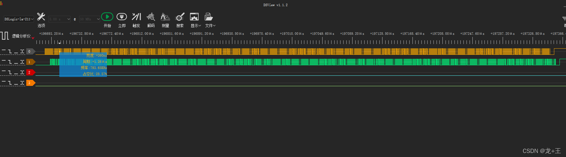
(2)查看细节-ws2812数据,周期1.25左右
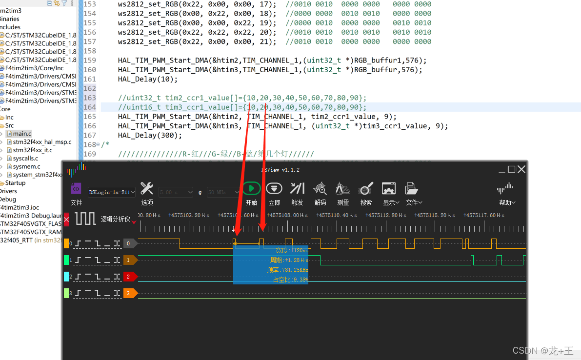
(3)查看细节-数组数据,因周期是105,那么10/105大约是9%左右
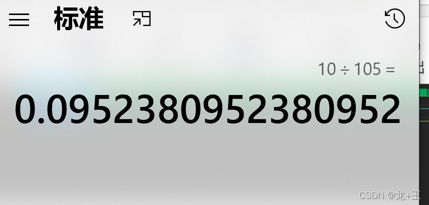
以下位数据情况
(8)后期补充-细节
对了忘记说了,所以后期补充下
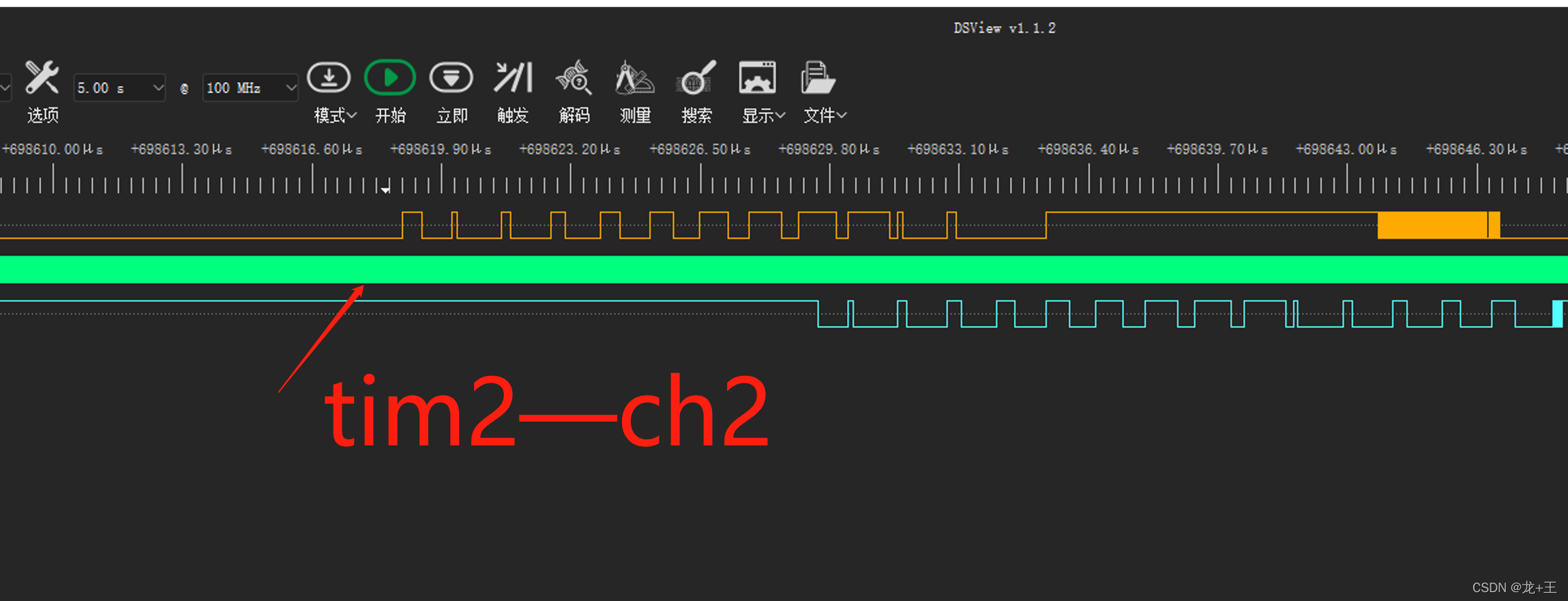
(1)在使用正点原子开发板子时 tim2ch2时发现数据波形不对,这是因为这款板子外挂模块所致,换了一块其他板子没有这个毛病。
抓到波形如下图
查找原理图。
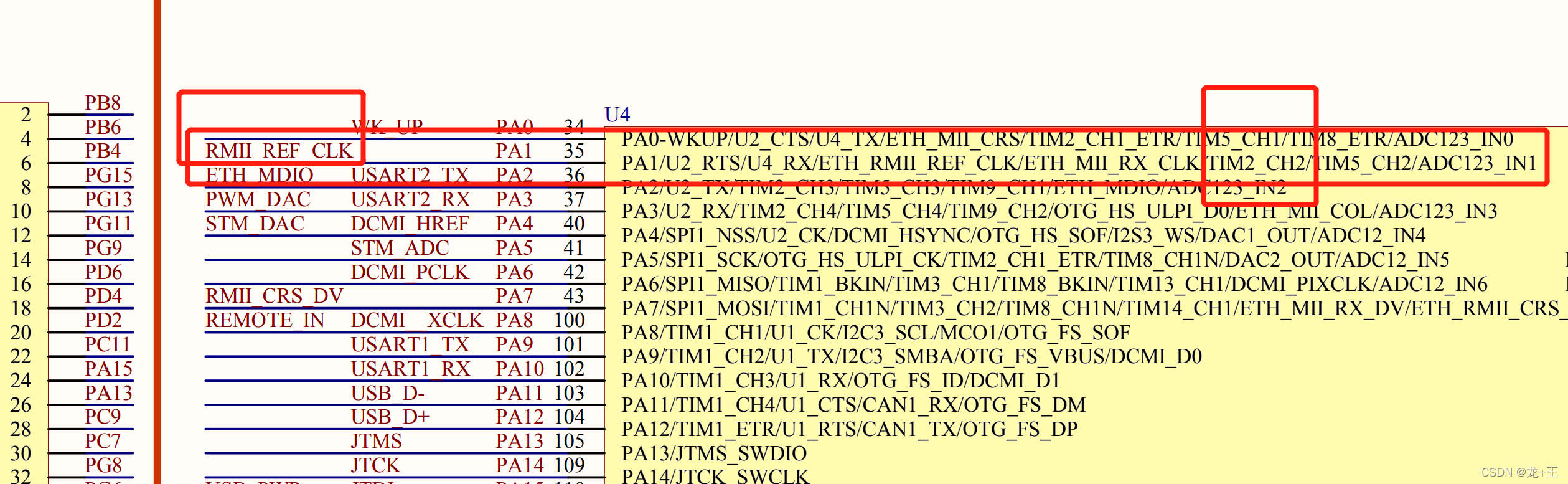
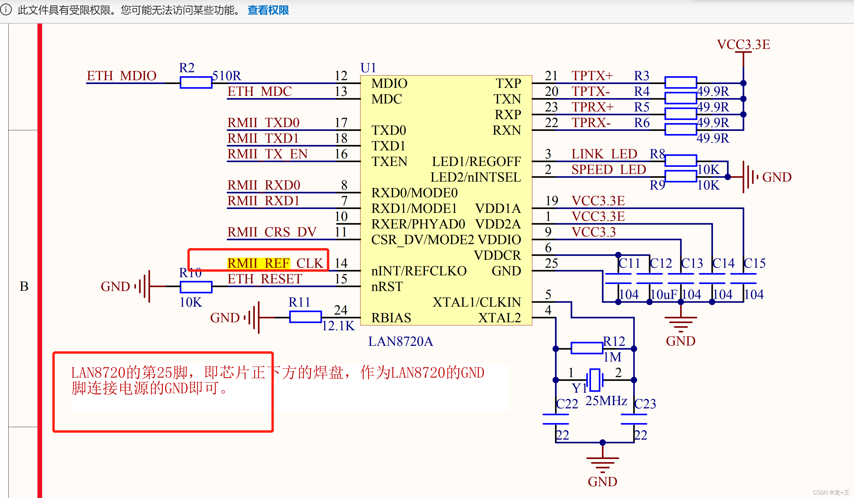
这个模块会影响。


 1272
1272

 被折叠的 条评论
为什么被折叠?
被折叠的 条评论
为什么被折叠?
 到【灌水乐园】发言


