


CPU加电后稳定后

此时CS的值为0xF000
EIP的值为0xFFF0
那么PC=(CS << 4) + EIP = 0xFFFF0
CPU要执行的第一条指令位于0xFFFF0处的指令
这条指令是个长跳转指令,跳转到0xF000:0xE05B处执行
可知BIOS实例就在这里
Bootloader
在BIOS完成系统硬件自检和把bootloader装载进内存之后,接下来就到bootloader干的活了。本文重点也旨在分析bootloader的代码。
bootloader的代码分为两大部分,一部分是bootasm.S,还有一部分是bootmain.c。下面分两个部分分析bootloader
bootasm.S
#include <asm.h>

# Start the CPU: switch to 32-bit protected mode, jump into C.
# The BIOS loads this code from the first sector of the hard disk into
# memory at physical address 0x7c00 and starts executing in real mode
# with %cs=0 %ip=7c00.

.set PROT_MODE_CSEG,        0x8                     # kernel code segment selector
.set PROT_MODE_DSEG,        0x10                    # kernel data segment selector
.set CR0_PE_ON,             0x1                     # protected mode enable flag

# start address should be 0:7c00, in real mode, the beginning address of the running bootloader
.globl start
start:
.code16                                             # Assemble for 16-bit mode
    cli                                             # Disable interrupts
    cld                                             # String operations increment

    # Set up the important data segment registers (DS, ES, SS).
    xorw %ax, %ax                                   # Segment number zero
    movw %ax, %ds                                   # -> Data Segment
    movw %ax, %es                                   # -> Extra Segment
    movw %ax, %ss                                   # -> Stack Segment

    # Enable A20:
    #  For backwards compatibility with the earliest PCs, physical
    #  address line 20 is tied low, so that addresses higher than
    #  1MB wrap around to zero by default. This code undoes this.
seta20.1:
    inb $0x64, %al                                  # Wait for not busy(8042 input buffer empty).
    testb $0x2, %al
    jnz seta20.1

    movb $0xd1, %al                                 # 0xd1 -> port 0x64
    outb %al, $0x64                                 # 0xd1 means: write data to 8042's P2 port

seta20.2:
    inb $0x64, %al                                  # Wait for not busy(8042 input buffer empty).
    testb $0x2, %al
    jnz seta20.2

    movb $0xdf, %al                                 # 0xdf -> port 0x60
    outb %al, $0x60                                 # 0xdf = 11011111, means set P2's A20 bit(the 1 bit) to 1

    # Switch from real to protected mode, using a bootstrap GDT
    # and segment translation that makes virtual addresses
    # identical to physical addresses, so that the
    # effective memory map does not change during the switch.
    lgdt gdtdesc
    movl %cr0, %eax
    orl $CR0_PE_ON, %eax
    movl %eax, %cr0

    # Jump to next instruction, but in 32-bit code segment.
    # Switches processor into 32-bit mode.
    ljmp $PROT_MODE_CSEG, $protcseg

.code32                                             # Assemble for 32-bit mode
protcseg:
    # Set up the protected-mode data segment registers
    movw $PROT_MODE_DSEG, %ax                       # Our data segment selector
    movw %ax, %ds                                   # -> DS: Data Segment
    movw %ax, %es                                   # -> ES: Extra Segment
    movw %ax, %fs                                   # -> FS
    movw %ax, %gs                                   # -> GS
    movw %ax, %ss                                   # -> SS: Stack Segment

    # Set up the stack pointer and call into C. The stack region is from 0--start(0x7c00)
    movl $0x0, %ebp
    movl $start, %esp
    call bootmain

    # If bootmain returns (it shouldn't), loop.
spin:
    jmp spin

# Bootstrap GDT
.p2align 2                                          # force 4 byte alignment
gdt:
    SEG_NULLASM                                     # null seg
    SEG_ASM(STA_X|STA_R, 0x0, 0xffffffff)           # code seg for bootloader and kernel
    SEG_ASM(STA_W, 0x0, 0xffffffff)                 # data seg for bootloader and kernel

gdtdesc:
    .word 0x17                                      # sizeof(gdt) - 1
    .long gdt                                       # address gdt
我们知道BIOS完成了它的任务之后,控制权就会交给位于0x7c00的bootloader来装入操作系统内核
代码第16行(cli)就是位于0x7c00处。
初始化段寄存器和不接受中断
cli                                             # Disable interrupts 禁用中断,在系统内核还未加载之前不理会硬件中断
cld                                             # String operations increment
cld指令将标志寄存器Flag的方向标志位DF清零。
在字串操作中使变址寄存器SI或DI的地址指针自动增加,字串处理由前往后。
xorw %ax, %ax                                   # Segment number zero 	ax与自身异或,结果是0
movw %ax, %ds                                   # -> Data Segment	    ds置0
movw %ax, %es                                   # -> Extra Segment
movw %ax, %ss                                   # -> Stack Segment
接下来四行将ax寄存器置0,然后把ds,es,ss三个段寄存器置0
  # Set up the important data segment registers (DS, ES, SS).
    xorw %ax, %ax                                   # Segment number zero
    movw %ax, %ds                                   # -> Data Segment
    movw %ax, %es                                   # -> Extra Segment
    movw %ax, %ss                                   # -> Stack Segment

    # Enable A20:
    #  For backwards compatibility with the earliest PCs, physical
    #  address line 20 is tied low, so that addresses higher than
    #  1MB wrap around to zero by default. This code undoes this.
seta20.1:
    inb $0x64, %al                                  # Wait for not busy(8042 input buffer empty).
    testb $0x2, %al
    jnz seta20.1

    movb $0xd1, %al                                 # 0xd1 -> port 0x64
    outb %al, $0x64                                 # 0xd1 means: write data to 8042's P2 port

seta20.2:
    inb $0x64, %al                                  # Wait for not busy(8042 input buffer empty).
    testb $0x2, %al
    jnz seta20.2

    movb $0xdf, %al                                 # 0xdf -> port 0x60
    outb %al, $0x60                                 # 0xdf = 11011111, means set P2's A20 bit(the 1 bit) to 1
开启A20
接下来这个部分开启A20地址线,这部分代码之所以存在还是一个兼容性的问题
https://www.zhihu.com/question/29375534关于为什么要开启A20地址线,可以参考这个链接
我也做一个简要的概括,就是Intel的i8086 CPU寄存器是16位的,但是地址线是20根,那么怎么用16位的数据表示20位的地址呢?
Intel用了分段的方法——segment:offset. 实际的地址是segment << 4 + offset.
举例说明,1000:FF03 表示的地址是 0x1000 << 4 + 0xFF03 即 0x1FF03
那这种方法,填满F表示的地址是多少呢?FFFF:FFFF = 0xFFFF << 4 + 0xFFFF = 0x10FFEF
0x10FFEF的二进制形式是多少呢0001 0000 1111 1111 1110 1111,有效位数是21位,第21位在以前的CPU上就被忽略了
但是现在的CPU地址线不止20根,主流64位CPU的地址线是48根,当老式的程序用FFFF:FFFF表示0xFFEF时,现在的CPU觉得它想说0x10FFEF,这就会出现兼容性问题,所以我们就要关掉21地址线即A20(A0是第一条)
但是当现代程序,包括现代操作系统想要访问1MB以上的内存空间时,就要打开这个A20,不然就会出现地址错误了。
那么如何开启A20呢?
https://www.cnblogs.com/mqmelon/p/4790820.html参考文章在这
总的来说一共有三种方法,但是其中有两种方法都不好,甚至可以说是危险的。安全的打开方法就是利用键盘控制器发送开启指令。代码在这里分为两个部分,都是先等待键盘空闲之后,发送数据到指定的端口,大概意思就是“把我下面的指令写到8042’s P2 port,这个指令是开启A20”
初始化gdt
开启了A20之后,接下来的任务就是建立gdt
lgdt gdtdesc
# Bootstrap GDT
.p2align 2                                          # force 4 byte alignment
gdt:
    SEG_NULLASM                                     # null seg
    SEG_ASM(STA_X|STA_R, 0x0, 0xffffffff)           # code seg for bootloader and kernel
    SEG_ASM(STA_W, 0x0, 0xffffffff)                 # data seg for bootloader and kernel

gdtdesc:
    .word 0x17                                      # sizeof(gdt) - 1
    .long gdt                                       # address gdt
gdt的参考文章可以看这个
https://zhuanlan.zhihu.com/p/25867829
gdt说得通俗一点就是一个结构体数组,什么样的结构体呢,用C语言描述就是这样的
struct gdt_entry {
    uint16_t limit_low;
    uint16_t base_low;
    uint8_t base_middle;
    uint8_t access;
    unsigned limit_high: 4;
    unsigned flags: 4;
    uint8_t base_high;
} __attribute__((packed));
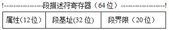
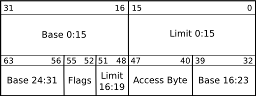
用图片来表示其中的内存排布是这样的,这个结构体就是一个段描述符,它占8个字节大,注意这里面limit_high和flag都是4bit的。
lgdt gdtdesc
这一行的意思是设置gdt的入口地址gdtdesc装入寄存器gdtr
那么gdtdesc里面写了什么呢,就是gdt这个结构体在内存中的基址和长度 - 1,这很好理解,C语言中的数组,第一个元素就在它的基址那里,最后一个元素的位置就在基址加长度减一的位置
那么gdt本身说了什么呢,代码中写了三行,一个是空的段描述符,还有一个是代码段描述符,还有一个是数据段描述符,设置段描述符这里它用了一个宏替换,写的非常晦涩。。。用C语言翻译过来的话差不多是这个意思
void gdt_install(uint8_t num, uint32_t base, uint32_t limit, uint8_t access, uint8_t flags) {

    /* Setup the descriptor base address */
    gdt[num].base_low = (base & 0xffff);
    gdt[num].base_middle = (base >> 16) & 0xff;
    gdt[num].base_high = (base >> 24) & 0xff;

    /* Setup the descriptor limits */
    gdt[num].limit_low = (limit & 0xffff);
    gdt[num].limit_high = ((limit >> 16) & 0x0f);

    /* Finally, set up the granularity and access flags */
    gdt[num].flags = flags;

    access |= AC_RE; // 设置保留位为1
    gdt[num].access = access;
}
在这里,把两个段都初始化成了基址为0,长度为0xFFFFFFFF的段,所以它们目前管理的是同一段内存空间。
使能和进入保护模式
初始化好了gdt,接下来就是让CPU进入保护模式,之后把控制权交给C编写的bootmain
    movl %cr0, %eax
    orl $CR0_PE_ON, %eax
    movl %eax, %cr0

    # Jump to next instruction, but in 32-bit code segment.
    # Switches processor into 32-bit mode.
    ljmp $PROT_MODE_CSEG, $protcseg

.code32                                             # Assemble for 32-bit mode
protcseg:
    # Set up the protected-mode data segment registers
    movw $PROT_MODE_DSEG, %ax                       # Our data segment selector
    movw %ax, %ds                                   # -> DS: Data Segment
    movw %ax, %es                                   # -> ES: Extra Segment
    movw %ax, %fs                                   # -> FS
    movw %ax, %gs                                   # -> GS
    movw %ax, %ss                                   # -> SS: Stack Segment

    # Set up the stack pointer and call into C. The stack region is from 0--start(0x7c00)
    movl $0x0, %ebp
    movl $start, %esp
    call bootmain
让CPU进入保护模式就是让cr0的第一个bit变成1,这个三行就实现了。
然后就是长跳转,进入32位的代码段,从这里开始,就是32位的保护模式下的代码了。
这里值得一说的就是 P R O T M O D E C S E G , 和 PROT_MODE_CSEG,和 PROTMODECSEG,和protcseg,前者是保护模式下的代码段选择子,通俗来说就是代码段的段描述符在gdt这个结构体中的下标,但是不一样的是C语言中结构体数组的下标是一个个的结构体为单位,这里0x8是字节,就是说代码段的段描述符相对于gdt的表头的偏移量是8字节,后者这个就是段机制下的寻址偏移量,我们知道段机制下的需要段描述符中的基址在加上外界的一个偏移量来寻址,前面代码段的基址是0.那么物理地址就是$protcseg了
接下来的几行将数据段的段选择子赋值给了其他几个段寄存器
最后三行建立栈帧,把帧指针赋值为0,栈指针赋值为start然后调用了bootmain函数
汇编部分先到这里,C部分接下来再干


 1653
1653


 被折叠的 条评论
为什么被折叠?
被折叠的 条评论
为什么被折叠?
 到【灌水乐园】发言


