


拓扑准备:
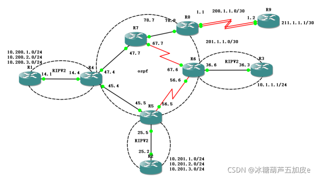
拓扑接口参考: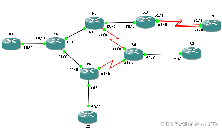
如图所示,是一个公司新型的网络拓扑图,其中R1为A部门,R2为B部门,R3为服务器。
R1和R4之间起RIPv2;
R2和R5之间起RIPv2;
R3和R6之间起RIPv2;
R4、R5、R6、R7、R8之间起OSPF;
实验需求:
- 公司通过双出口跟外网通信,要求全网互通,R1、R2、R3可以和外网(211.1.1.1)通信。
- 平时的时候A部门通过线路200.1.1.0/30,B部门通过线路201.1.1.0/30,当一个线路出现问题时,能切换到另一个线路跟外网通信。双向备份
- 现在要对网络环境进行优化,要求R1、R2、R3的路由表条目尽量少,并且各自用不同的方法。
- 因客户需求,B部门去往外网的数据需走R6,回来的数据走R4。
需求1:公司通过双出口跟外网通信,要求全网互通,R1、R2、R3可以和外网(211.1.1.1)通信。
IP地址配置:
R1(config)#int f0/0
R1(config-if)#ip add 14.14.14.1 255.255.255.0
R4(config-if)#no shutdown
R1(config-if)#exit
R1(config)#int lo0
R1(config-if)#ip add 10.200.1.1 255.255.255.0————回环口路由通常用于模拟部门内网路由条目
R1(config)#int lo1
R1(config-if)#ip add 10.200.2.1 255.255.255.0
R1(config)#int lo2
R1(config-if)#ip add 10.200.3.1 255.255.255.0
查看配置是否成功:
R1#show ip int b
Interface                  IP-Address      OK? Method Status                Protocol
FastEthernet0/0            14.14.14.1      YES manual up                    up
FastEthernet0/1            unassigned      YES unset  administratively down down
Loopback0                  10.200.1.1      YES manual up                    up
Loopback1                  10.200.2.1      YES manual up                    up
Loopback2                  10.200.3.1      YES manual up                    up
其他设备同理配置
R1和R4之间起RIPv2;
R2和R5之间起RIPv2;
R3和R6之间起RIPv2;
R1(config)#router rip ——————进入RIP进程
R1(config-router)#version 2————设置为RIPv2
R1(config-router)#no auto-summary
R1(config-router)#network 14.0.0.0————通告直连条目
R1(config-router)#network 10.0.0.0————通告回环口条目
R4(config)#router rip
R4(config-router)#version 2
R4(config-router)#no auto-summary
R4(config-router)#network 14.14.14.0
验证RIP是否通告成功
R4#show ip route rip
     10.0.0.0/24 is subnetted, 3 subnets
R       10.200.2.0 [120/1] via 14.14.14.1, 00:00:28, FastEthernet0/0
R       10.200.3.0 [120/1] via 14.14.14.1, 00:00:28, FastEthernet0/0
R       10.200.1.0 [120/1] via 14.14.14.1, 00:00:28, FastEthernet0/0
其他部门同理配置
R4、R5、R6、R7、R8之间起OSPF
R4(config)#router ospf 1——————————————————进入ospf进程
R4(config-router)#network 47.47.47.0 0.0.0.255 area 0————将直连条目通告进骨干区域,区域0
R4(config-router)#network 45.45.45.0 0.0.0.255 area 0
R5(config)#router ospf 1
R5(config-router)#network 45.45.45.0 0.0.0.255 a 0
R5(config-router)#network 56.56.56.0 0.0.0.255 area 0
R8(config)#router ospf 1
R8(config-router)#network 78.78.78.0 0.0.0.255 a 0
验证OSPF邻居是否建立成功
R7#show ip ospf neighbor

Neighbor ID     Pri   State           Dead Time   Address         Interface
67.67.67.6        0   FULL/  -        00:00:30    67.67.67.6      Serial1/0
47.47.47.4        1   FULL/DR         00:00:32    47.47.47.4      FastEthernet0/0
201.1.1.1         1   FULL/BDR        00:00:36    78.78.78.8      FastEthernet0/1
其他设备同理,通告要参与通信的路由条目(直连条目)
由于R4、R5、R6这几台路由器上有两种协议,所以要分别做双向重分发。并且协议各自通告不同的路由条目,将路由条目分别重分发进不同的协议里面
R4(config)#router rip
R4(config-router)#redistribute ospf 1 metric 3———由于rip的防环机制(最大rip路由metric为15,16则不可达),因此将ospf路由通告进RIP时候需要带上metric
R4(config)#router ospf 1
R4(config-router)#redistribute rip subnets ———通告进OSPF进程的路由条目要带上明细subnets
其他设备同理操作
此时R1、R2、R3回环口都可以ping通R8
R1#ping 78.78.78.8 source lo0
Type escape sequence to abort.
Sending 5, 100-byte ICMP Echos to 78.78.78.8, timeout is 2 seconds:
Packet sent with a source address of 10.200.1.1
!!!!!
Success rate is 100 percent (5/5), round-trip min/avg/max = 196/248/384 ms
由于R8作为与外网通信的边界路由器,而且R8于R9是双出口的链接,因此要在R8上配置双向NAT
R8(config)#access-list 1 permit 10.0.0.0 0.255.255.255————标准访问控制列表匹配R1、R2、R3的回环扣的路由条目
创建一个路由图nat1和路由图nat2,调用ACL
R8(config)#route-map nat1 permit 10
R8(config-route-map)#match ip address 1————调用标准访问控制列表
R8(config-route-map)#match interface serial 1/0———匹配接口S1/0
R8(config-route-map)#exit
R8(config)#route-map nat2 permit 10
R8(config-route-map)#match ip address 1————调用标准访问控制列表
R8(config-route-map)#match interface serial 1/1———匹配接口S1/1
双出口网关用策略路由PBR应用于NAT
R8(config)#int s1/1
R8(config-if)#ip nat outside
R8(config-if)#int s1/0
R8(config-if)#ip nat outside
R8(config-if)#int f0/0
R8(config-if)#ip nat inside
R8(config)#ip nat inside source route-map nat1 interface s1/0 overload————S1/0接口下调用路由图
R8(config)#ip nat inside source route-map nat2 interface s1/1 overload————S1/1接口下调用路由图
关键来了
show ip route 可以看到R7内网中路由器并不存在外网211.1.1.1的路由
R7#show ip route
Codes: C - connected, S - static, R - RIP, M - mobile, B - BGP
       D - EIGRP, EX - EIGRP external, O - OSPF, IA - OSPF inter area
       N1 - OSPF NSSA external type 1, N2 - OSPF NSSA external type 2
       E1 - OSPF external type 1, E2 - OSPF external type 2
       i - IS-IS, su - IS-IS summary, L1 - IS-IS level-1, L2 - IS-IS level-2
       ia - IS-IS inter area, * - candidate default, U - per-user static route
       o - ODR, P - periodic downloaded static route

Gateway of last resort is not set

     67.0.0.0/24 is subnetted, 1 subnets
C       67.67.67.0 is directly connected, Serial1/0
     25.0.0.0/24 is subnetted, 1 subnets
O E2    25.25.25.0 [110/20] via 47.47.47.4, 2d19h, FastEthernet0/0
     10.0.0.0/24 is subnetted, 6 subnets
O E2    10.201.3.0 [110/20] via 47.47.47.4, 2d19h, FastEthernet0/0
O E2    10.200.2.0 [110/20] via 47.47.47.4, 2d20h, FastEthernet0/0
O E2    10.201.2.0 [110/20] via 47.47.47.4, 2d19h, FastEthernet0/0
O E2    10.200.3.0 [110/20] via 47.47.47.4, 2d20h, FastEthernet0/0
O E2    10.201.1.0 [110/20] via 47.47.47.4, 2d19h, FastEthernet0/0
O E2    10.200.1.0 [110/20] via 47.47.47.4, 2d20h, FastEthernet0/0
     78.0.0.0/24 is subnetted, 1 subnets
C       78.78.78.0 is directly connected, FastEthernet0/1
     56.0.0.0/24 is subnetted, 1 subnets
O       56.56.56.0 [110/66] via 47.47.47.4, 2d20h, FastEthernet0/0
     47.0.0.0/24 is subnetted, 1 subnets
C       47.47.47.0 is directly connected, FastEthernet0/0
     14.0.0.0/24 is subnetted, 1 subnets
O E2    14.14.14.0 [110/20] via 47.47.47.4, 2d20h, FastEthernet0/0
     45.0.0.0/24 is subnetted, 1 subnets
O       45.45.45.0 [110/2] via 47.47.47.4, 2d20h, FastEthernet0/0
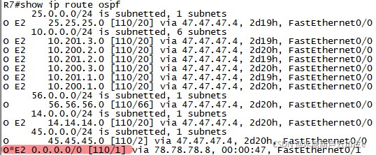
此时因为R8相当于是内网网关,因此可以在内网网关的OSPF进程下,下放一条默认路由指向自己
R8(config)#router ospf 1
R8(config-router)#default-information originate always
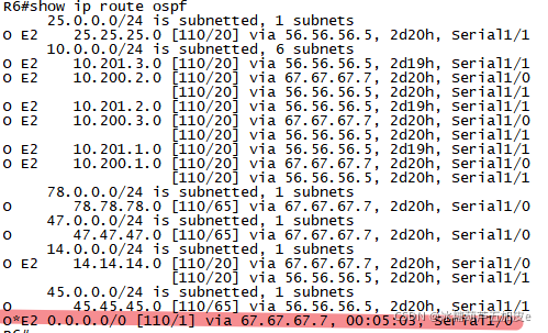
可以看到所有中间路由器的路由表都存在一条指向网关路由器的默认路由
这时候还是ping不通,因为R8也没有211.1.1.1的路由条目
R1#ping 211.1.1.1 source lo0
Type escape sequence to abort.
Sending 5, 100-byte ICMP Echos to 211.1.1.1, timeout is 2 seconds:
Packet sent with a source address of 10.200.1.1
UUUUU
Success rate is 0 percent (0/5)
R8(config)#ip route 0.0.0.0 0.0.0.0 200.1.1.2————手工在R8上指定一条默认路由指向R9
R8(config)#ip route 0.0.0.0 0.0.0.0 201.1.1.2
R1#ping 211.1.1.1 source lo0
Type escape sequence to abort.
Sending 5, 100-byte ICMP Echos to 211.1.1.1, timeout is 2 seconds:
Packet sent with a source address of 10.200.1.1
!!!!!
Success rate is 100 percent (5/5), round-trip min/avg/max = 276/340/440 ms
到这里第一个需求完成!
需求2:平时的时候A部门通过线路200.1.1.0/30,B部门通过线路201.1.1.0/30,当一个线路出现问题时,能切换到另一个线路跟外网通信。双向备份
配置策略路由,将R1的路由流量分配给S1/0接口,把R2的流量分配给S1/1接口。创建路由图,对它执行动作,将下一条原本为200.1.1.1的改为 201.1.1.2,将下一条原本为201.1.1.2的改为下一跳为200.1.1.2。以此来改变路径
R8(config)#access-list 10 permit 10.200.0.0 0.0.255.255————匹配A部门条目
R8(config)#access-list 20 permit 10.201.0.0 0.0.255.255————匹配B部门条目
R8(config)#route-map PBR permit 10
R8(config-route-map)#match ip address 10 ————————调用A部门路由条目
R8(config-route-map)#set ip next-hop 200.1.1.2 201.1.1.2————下一跳地址优选200,备选201
R8(config)#route-map PBR permit 20
R8(config-route-map)#match ip address 20 ————————调用B部门路由条目
R8(config-route-map)#set ip next-hop 201.1.1.2 200.1.1.2————下一跳地址优选201,备选200
R8(config)#int f0/0
R8(config-if)#ip policy route-map PBR————在接口下调用路由策略,路由图
验证:
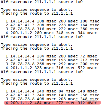
R1走200这条链路
R1#traceroute 211.1.1.1 source lo0
Type escape sequence to abort.
Tracing the route to 211.1.1.1
  1 14.14.14.4 68 msec 176 msec 80 msec
  2 47.47.47.7 236 msec 304 msec 252 msec
  3 78.78.78.8 380 msec 312 msec 348 msec
  4 200.1.1.2 376 msec 352 msec 336 msec
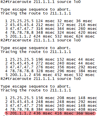
R2走201这条链路
R2#traceroute 211.1.1.1 source lo0
Type escape sequence to abort.
Tracing the route to 211.1.1.1
  1 25.25.25.5 144 msec 44 msec 148 msec
  2 45.45.45.4 240 msec 200 msec 292 msec
  3 47.47.47.7 496 msec 368 msec 384 msec
  4 78.78.78.8 332 msec 420 msec 352 msec
  5 201.1.1.2 444 msec 336 msec 420 msec
模拟链路故障:
R8(config)#int s1/1
R8(config-if)#shutdown
200链路down时候
R1#traceroute 211.1.1.1 source lo0
Type escape sequence to abort.
Tracing the route to 211.1.1.1
  1 14.14.14.4 184 msec 200 msec 72 msec
  2 47.47.47.7 168 msec 196 msec 212 msec
  3 78.78.78.8 268 msec 292 msec 200 msec
  4 201.1.1.2 328 msec 316 msec 532 msec
R8(config)#int s1/0
R8(config-if)#shutdown
201链路down时候
R2#traceroute 211.1.1.1 source lo0
Type escape sequence to abort.
Tracing the route to 211.1.1.1
  1 25.25.25.5 124 msec 136 msec 108 msec
  2 45.45.45.4 248 msec 320 msec 184 msec
  3 47.47.47.7 372 msec 316 msec 220 msec
  4 78.78.78.8 256 msec 220 msec 336 msec
  5 200.1.1.2 276 msec 372 msec 368 msec
故障恢复时候,链路按正常情况下转发
到这里第二个需求完成!
需求3:现在要对网络环境进行优化,要求R1、R2、R3的路由表条目尽量少,并且各自用不同的方法。
方法一:被动接口
由于被动接口只接收更新,不发送更新,为了使R1的条目尽量少,则在R4上,和R1相连的接口上配置被动接口
R4(config)#router rip
R4(config-router)#passive-interface f0/0
配置前路由表:
R1#show ip route
Codes: C - connected, S - static, R - RIP, M - mobile, B - BGP
       D - EIGRP, EX - EIGRP external, O - OSPF, IA - OSPF inter area
       N1 - OSPF NSSA external type 1, N2 - OSPF NSSA external type 2
       E1 - OSPF external type 1, E2 - OSPF external type 2
       i - IS-IS, su - IS-IS summary, L1 - IS-IS level-1, L2 - IS-IS level-2
       ia - IS-IS inter area, * - candidate default, U - per-user static route
       o - ODR, P - periodic downloaded static route

Gateway of last resort is 14.14.14.4 to network 0.0.0.0

     67.0.0.0/24 is subnetted, 1 subnets
R       67.67.67.0 [120/3] via 14.14.14.4, 00:00:22, FastEthernet0/0
     25.0.0.0/24 is subnetted, 1 subnets
R       25.25.25.0 [120/3] via 14.14.14.4, 00:00:22, FastEthernet0/0
     10.0.0.0/24 is subnetted, 6 subnets
R       10.201.3.0 [120/3] via 14.14.14.4, 00:00:22, FastEthernet0/0
C       10.200.2.0 is directly connected, Loopback1
R       10.201.2.0 [120/3] via 14.14.14.4, 00:00:22, FastEthernet0/0
C       10.200.3.0 is directly connected, Loopback2
R       10.201.1.0 [120/3] via 14.14.14.4, 00:00:03, FastEthernet0/0
C       10.200.1.0 is directly connected, Loopback0
     78.0.0.0/24 is subnetted, 1 subnets
R       78.78.78.0 [120/3] via 14.14.14.4, 00:00:03, FastEthernet0/0
     56.0.0.0/24 is subnetted, 1 subnets
R       56.56.56.0 [120/3] via 14.14.14.4, 00:00:03, FastEthernet0/0
     47.0.0.0/24 is subnetted, 1 subnets
R       47.47.47.0 [120/3] via 14.14.14.4, 00:00:03, FastEthernet0/0
     14.0.0.0/24 is subnetted, 1 subnets
C       14.14.14.0 is directly connected, FastEthernet0/0
     45.0.0.0/24 is subnetted, 1 subnets
R       45.45.45.0 [120/3] via 14.14.14.4, 00:00:03, FastEthernet0/0
R*   0.0.0.0/0 [120/1] via 14.14.14.4, 00:00:03, FastEthernet0/0
配置后路由表:
R1#clear ip route *——————————————路由表清除
R1#show ip route
Codes: C - connected, S - static, R - RIP, M - mobile, B - BGP
       D - EIGRP, EX - EIGRP external, O - OSPF, IA - OSPF inter area
       N1 - OSPF NSSA external type 1, N2 - OSPF NSSA external type 2
       E1 - OSPF external type 1, E2 - OSPF external type 2
       i - IS-IS, su - IS-IS summary, L1 - IS-IS level-1, L2 - IS-IS level-2
       ia - IS-IS inter area, * - candidate default, U - per-user static route
       o - ODR, P - periodic downloaded static route

Gateway of last resort is not set

     10.0.0.0/24 is subnetted, 3 subnets
C       10.200.2.0 is directly connected, Loopback1
C       10.200.3.0 is directly connected, Loopback2
C       10.200.1.0 is directly connected, Loopback0
     14.0.0.0/24 is subnetted, 1 subnets
C       14.14.14.0 is directly connected, FastEthernet0/0
但是此时会发现R1默认路由同时也被抑制了
所以要在R1上手工配置一条默认路由指向R4,保证R1可以访问外网
R1(config)#ip route 0.0.0.0 0.0.0.0 14.14.14.4
此时R1在不影响通信的同时减少了路由表条目
R1#ping 211.1.1.1 so lo0
Type escape sequence to abort.
Sending 5, 100-byte ICMP Echos to 211.1.1.1, timeout is 2 seconds:
Packet sent with a source address of 10.200.1.1
!!!!!
方法2:进程下放默认路由代替重分发
在R5上取消重分发进RIP,在rip进程下放一条默认路由
R5(config)#router rip
R5(config-router)#no redistribute ospf 1 metric 3
R5(config-router)#default-information originate
配置前
R2#show ip route
Codes: C - connected, S - static, R - RIP, M - mobile, B - BGP
       D - EIGRP, EX - EIGRP external, O - OSPF, IA - OSPF inter area
       N1 - OSPF NSSA external type 1, N2 - OSPF NSSA external type 2
       E1 - OSPF external type 1, E2 - OSPF external type 2
       i - IS-IS, su - IS-IS summary, L1 - IS-IS level-1, L2 - IS-IS level-2
       ia - IS-IS inter area, * - candidate default, U - per-user static route
       o - ODR, P - periodic downloaded static route

Gateway of last resort is 25.25.25.5 to network 0.0.0.0

     67.0.0.0/24 is subnetted, 1 subnets
R       67.67.67.0 [120/3] via 25.25.25.5, 00:00:12, FastEthernet0/0
     25.0.0.0/24 is subnetted, 1 subnets
C       25.25.25.0 is directly connected, FastEthernet0/0
     10.0.0.0/24 is subnetted, 6 subnets
C       10.201.3.0 is directly connected, Loopback2
R       10.200.2.0 [120/3] via 25.25.25.5, 00:00:12, FastEthernet0/0
C       10.201.2.0 is directly connected, Loopback1
R       10.200.3.0 [120/3] via 25.25.25.5, 00:00:12, FastEthernet0/0
C       10.201.1.0 is directly connected, Loopback0
R       10.200.1.0 [120/3] via 25.25.25.5, 00:00:20, FastEthernet0/0
     78.0.0.0/24 is subnetted, 1 subnets
R       78.78.78.0 [120/3] via 25.25.25.5, 00:00:20, FastEthernet0/0
     56.0.0.0/24 is subnetted, 1 subnets
R       56.56.56.0 [120/3] via 25.25.25.5, 00:00:23, FastEthernet0/0
     47.0.0.0/24 is subnetted, 1 subnets
R       47.47.47.0 [120/3] via 25.25.25.5, 00:00:23, FastEthernet0/0
     14.0.0.0/24 is subnetted, 1 subnets
R       14.14.14.0 [120/3] via 25.25.25.5, 00:00:23, FastEthernet0/0
     45.0.0.0/24 is subnetted, 1 subnets
R       45.45.45.0 [120/3] via 25.25.25.5, 00:00:23, FastEthernet0/0
R*   0.0.0.0/0 [120/1] via 25.25.25.5, 00:00:22, FastEthernet0/0
配置后
R2#show ip route
Codes: C - connected, S - static, R - RIP, M - mobile, B - BGP
       D - EIGRP, EX - EIGRP external, O - OSPF, IA - OSPF inter area
       N1 - OSPF NSSA external type 1, N2 - OSPF NSSA external type 2
       E1 - OSPF external type 1, E2 - OSPF external type 2
       i - IS-IS, su - IS-IS summary, L1 - IS-IS level-1, L2 - IS-IS level-2
       ia - IS-IS inter area, * - candidate default, U - per-user static route
       o - ODR, P - periodic downloaded static route

Gateway of last resort is 25.25.25.5 to network 0.0.0.0

     25.0.0.0/24 is subnetted, 1 subnets
C       25.25.25.0 is directly connected, FastEthernet0/0
     10.0.0.0/24 is subnetted, 3 subnets
C       10.201.3.0 is directly connected, Loopback2
C       10.201.2.0 is directly connected, Loopback1
C       10.201.1.0 is directly connected, Loopback0
R*   0.0.0.0/0 [120/1] via 25.25.25.5, 00:00:06, FastEthernet0/0
且不影响通信
R2#ping 211.1.1.1 so lo0
Type escape sequence to abort.
Sending 5, 100-byte ICMP Echos to 211.1.1.1, timeout is 2 seconds:
Packet sent with a source address of 10.201.1.1
!!!!!
Success rate is 100 percent (5/5), round-trip min/avg/max = 260/372/484 ms
方法3:调用前缀列表
配置前缀列表,只允许默认路由经过。并在RIP进程的出方向下调用
R6(config)#ip prefix-list mrly permit 0.0.0.0/0
R6(config)#router rip
R6(config-router)#no redistribute ospf 1 metric 3
R6(config-router)#distribute-list prefix mrly out
配置前
R3#show ip route
Codes: C - connected, S - static, R - RIP, M - mobile, B - BGP
       D - EIGRP, EX - EIGRP external, O - OSPF, IA - OSPF inter area
       N1 - OSPF NSSA external type 1, N2 - OSPF NSSA external type 2
       E1 - OSPF external type 1, E2 - OSPF external type 2
       i - IS-IS, su - IS-IS summary, L1 - IS-IS level-1, L2 - IS-IS level-2
       ia - IS-IS inter area, * - candidate default, U - per-user static route
       o - ODR, P - periodic downloaded static route

Gateway of last resort is 36.36.36.6 to network 0.0.0.0

     36.0.0.0/24 is subnetted, 1 subnets
C       36.36.36.0 is directly connected, FastEthernet0/0
     67.0.0.0/24 is subnetted, 1 subnets
R       67.67.67.0 [120/3] via 36.36.36.6, 00:00:22, FastEthernet0/0
     25.0.0.0/24 is subnetted, 1 subnets
R       25.25.25.0 [120/3] via 36.36.36.6, 00:00:22, FastEthernet0/0
     10.0.0.0/24 is subnetted, 7 subnets
C       10.1.1.0 is directly connected, Loopback0
R       10.201.3.0 [120/3] via 36.36.36.6, 00:00:22, FastEthernet0/0
R       10.200.2.0 [120/3] via 36.36.36.6, 00:00:31, FastEthernet0/0
R       10.201.2.0 [120/3] via 36.36.36.6, 00:00:31, FastEthernet0/0
R       10.200.3.0 [120/3] via 36.36.36.6, 00:00:31, FastEthernet0/0
R       10.201.1.0 [120/3] via 36.36.36.6, 00:00:31, FastEthernet0/0
R       10.200.1.0 [120/3] via 36.36.36.6, 00:00:31, FastEthernet0/0
     78.0.0.0/24 is subnetted, 1 subnets
R       78.78.78.0 [120/3] via 36.36.36.6, 00:00:31, FastEthernet0/0
     56.0.0.0/24 is subnetted, 1 subnets
R       56.56.56.0 [120/3] via 36.36.36.6, 00:00:31, FastEthernet0/0
     47.0.0.0/24 is subnetted, 1 subnets
R       47.47.47.0 [120/3] via 36.36.36.6, 00:00:31, FastEthernet0/0
     14.0.0.0/24 is subnetted, 1 subnets
R       14.14.14.0 [120/3] via 36.36.36.6, 00:00:31, FastEthernet0/0
     45.0.0.0/24 is subnetted, 1 subnets
R       45.45.45.0 [120/3] via 36.36.36.6, 00:00:31, FastEthernet0/0
R*   0.0.0.0/0 [120/1] via 36.36.36.6, 00:00:02, FastEthernet0/0
配置后
R3#show ip route
Codes: C - connected, S - static, R - RIP, M - mobile, B - BGP
       D - EIGRP, EX - EIGRP external, O - OSPF, IA - OSPF inter area
       N1 - OSPF NSSA external type 1, N2 - OSPF NSSA external type 2
       E1 - OSPF external type 1, E2 - OSPF external type 2
       i - IS-IS, su - IS-IS summary, L1 - IS-IS level-1, L2 - IS-IS level-2
       ia - IS-IS inter area, * - candidate default, U - per-user static route
       o - ODR, P - periodic downloaded static route

Gateway of last resort is 36.36.36.6 to network 0.0.0.0

     36.0.0.0/24 is subnetted, 1 subnets
C       36.36.36.0 is directly connected, FastEthernet0/0
     10.0.0.0/24 is subnetted, 1 subnets
C       10.1.1.0 is directly connected, Loopback0
R*   0.0.0.0/0 [120/1] via 36.36.36.6, 00:00:27, FastEthernet0/0
且不影响通信
R3#ping 211.1.1.1 source loopback 0
Type escape sequence to abort.
Sending 5, 100-byte ICMP Echos to 211.1.1.1, timeout is 2 seconds:
Packet sent with a source address of 10.1.1.1
!!!!!
Success rate is 100 percent (5/5), round-trip min/avg/max = 296/386/472 ms
到这里需求三完成
需求4:因客户需求,B部门去往外网的数据需走R6,回来的数据走R4。
原来路径R2访问外网走R5
R2#traceroute 211.1.1.1 source lo0
Type escape sequence to abort.
Tracing the route to 211.1.1.1

  1 25.25.25.5 52 msec 160 msec 84 msec
  2 45.45.45.4 156 msec 308 msec 208 msec
  3 47.47.47.7 304 msec 272 msec 348 msec
  4 78.78.78.8 388 msec 344 msec 332 msec
  5 201.1.1.2 472 msec 648 msec 428 msec
R5(config)#access-list 11 permit 10.201.0.0 0.0.255.255
R5(config)#route-map PBR1 permit 10
R5(config-route-map)#match ip address 11
R5(config-route-map)#set ip next-hop 56.56.56.6 45.45.45.4
R5(config)#int f0/1
R5(config-if)# ip policy route-map PBR1
改完后流量走R6访问外网
R2#traceroute 211.1.1.1 source lo0

Type escape sequence to abort.
Tracing the route to 211.1.1.1

  1 25.25.25.5 76 msec 256 msec 76 msec
  2 56.56.56.6 140 msec 148 msec 108 msec
  3 67.67.67.7 228 msec 420 msec 312 msec
  4 78.78.78.8 368 msec 332 msec 388 msec
  5 201.1.1.2 440 msec 500 msec 300 msec
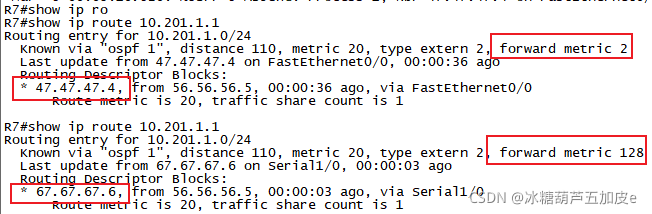
由于R7和R6之间是串型链路,在ospf中串型链路的metric更大,所以在R7设备上R4传来的10.201条目更优,因此条目会优先加表,所以访问R2内网时候会优先选择走R4
模拟故障,前后路由对比
R4(config)#int f0/1
R4(config-if)#shutdown
此时链路走R6
R8#traceroute 10.201.1.1 source f0/0
Type escape sequence to abort.
Tracing the route to 10.201.1.1
  1 78.78.78.7 36 msec 108 msec 72 msec
  2 67.67.67.6 168 msec 228 msec 124 msec
  3 56.56.56.5 148 msec 144 msec 208 msec
  4 25.25.25.2 428 msec 252 msec 288 msec
故障恢复
R4(config)#int f0/1
R4(config-if)#no shutdown
链路走R4
R8#traceroute 10.201.1.1 source f0/0
Type escape sequence to abort.
Tracing the route to 10.201.1.1
  1 78.78.78.7 76 msec 140 msec 172 msec
  2 47.47.47.4 284 msec 104 msec 208 msec
  3 45.45.45.5 176 msec 188 msec 268 msec
  4 25.25.25.2 388 msec 376 msec 440 msec


 1万+
1万+


 被折叠的 条评论
为什么被折叠?
被折叠的 条评论
为什么被折叠?
 到【灌水乐园】发言


