


一、数字频率计功能
(1)设计一个4位数字显示的十进制频率计,其测量范围为1MHz。
(2)测量值通过4个数码管显示以8421BCD码形式输出;
(3)采用记忆显示方式,即计数过程中不显示数据,待计数过程结束后,显示计数结果,并将此显示结果保持到下一次计数结束。显示时间应不小于1s。
(4)可通过开关实现量程控制,量程分10kHz、100kHz、1MHz三档(最大读数分别为9.999kHz、99.99kHz、999.9kHz);
当输入信号的频率大于相应量程时,有溢出显示。
二、所用设备
SE-5M型EDA实验系统资源( EPF10K10LC84-4)。SE-5M型实验箱通用编程模块,开关按键模块,LED显示模块,数码管显示模块。
三、基本设计原理

数字频率计的原理框图如图所示。他主要由4个模块组成,分别是:控制模块、计数模块电路、锁存器、译码显示模块。 当系统正常工作时,脉冲发生器提供的1 Hz的输入信号,经过控制模块进行信号的变换,产生计数信号,被测信号送入计数模块,计数模块对输入的矩形波进行计数,将计数结果送入锁存器中,保证系统可以稳定显示数据,显示译码驱动电路将二进制表示的计数结果转换成相应的能够在七段数码显示管上可以显示的十进制结果。在数码显示管上可以看到计数结果。
四、设计实现
**1、**系统方框图的划分和结构设计
根据数字频率计的系统原理框图(图1),设计系统的顶层电路图如图2所示。

Control模块将系统时钟转换为计数时钟。
suocun为锁存器。在信号lock的上升沿时,立即对模块的输入口的数据锁存到suocun块的内部,输出端输出送扫描显示译码模块可以译码输出。在这里使用了锁存器,好处是可以稳定显示数据,不会由于周期性的清零信号而不断闪烁。
counter计数模块,内部由3个计数器组成,分别为10进制、100进制和9999进制,有一时钟使能en输入,当高电平时允许计数,低电平时禁止计数。
show为扫描显示译码电路,可以将频率计数的结果译成能在数码管上显示相对应的阿拉伯数字,便于读取测量的结果。
为了实现系统功能,各个模块存在一个工作时序的问题,设计时需要综合考虑。
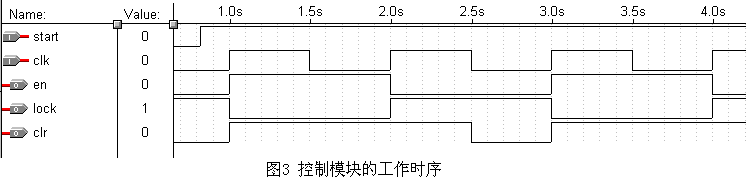
图3给出了系统的工作时序。图3中CLK是由图1中脉冲发生器产生的频率为1 Hz的标准时钟信号,当计数模块的en端为高电平时允许计数、低电平时停止计数,在停止计数期间,控制模块的lock端产生一个上升沿,将计数器在前1 s的计数值保存在锁存器中,并由5个7段译码器将计数结果译出稳定显示。锁存信号之后经过半个CLK周期,控制模块的clr端产生一个上升沿,对计数器进行清零。为下1 s的计数操作做准备。
为了产生这个时序图,首先有一个D触发器构成二分频器,在每次时钟CLK的上升沿到来使其值翻转。D触发器的输出高电平正好是1 s,因此可以作为计数模块的en端,用来控制计数。而lock信号正好是en端信号的翻转。在计数结束后半个CLK周期,CLK与en都为低电平,这时CLR产生一个上升沿作为清零信号。
2、各模块的VHDL源程序及仿真
A、control模块
library ieee;
use ieee.std_logic_1164.all;
entity control is
   port(clk:in std_logic; --系统时钟
        start:in std_logic;
        en,clr,lock : out std_logic);
end control;
architecture a of control is
begin
p1: process(clk)
variable clr1:std_logic;
variable en1,clk1:std_logic;
begin
  if clk'event and clk='1' then
     if start='1'then
        en1:=not en1;
     else
        en1:='0';
        clk1:='0';
     end if;
  end if;
en<=en1;
lock<=not en1;
clk1:=clk or en1;
clr<=clk1;
end process p1;
end a;
仿真图形如图3所示。
B、counter模块
library ieee;
use ieee.std_logic_1164.all;
use ieee.std_logic_unsigned.all;
entity counter is
  port(sig,en,clr,lch,start:in std_logic;--sig :待测信号  lch :量程控制 clr:清0信号
       overflow:out std_logic;--溢出信号
       counter1:out std_logic_vector(3 downto 0);
       counter2:out std_logic_vector(3 downto 0);
       counter3:out std_logic_vector(3 downto 0);
       counter4:out std_logic_vector(3 downto 0);
       dang: out std_logic_vector(1 downto 0));--档位输出
end counter;
architecture aa of counter is
signal dw :std_logic_vector(1 downto 0);  --档位
signal clk1:std_logic;--驱动计数器脉冲
begin
p1:process(lch)
variable count :std_logic_vector(1 downto 0);
begin
  if lch'event and lch='1'then
     if count="10" then
        count:="00";
     else
        count:=count+1;
     end if;
  end if;
case count is
   when "00"=>dang<="01";
   when "01"=>dang<="10";
   when "10"=>dang<="11";
   when others=>null;
end case;
dw<=count;
end process p1;
p2: process(sig)
variable clk2:std_logic;
variable counter:std_logic_vector(3 downto 0);--10 进制计数器
variable ccounter:std_logic_vector(6 downto 0);--100 进制计数器
begin
if dw="00"then
      clk2:=sig;--1档直接输出
elsif sig'event and sig='1' then
   if dw="01"then
      if counter="1001" then
         counter:=counter+"0111";
         clk2:='1';
      else
         counter:=counter+1;
         clk2:='0';
      end if;--2 档没10 个输出一个
   elsif dw="10" then
      if ccounter="1100011" then
         ccounter:="0000000";
         clk2:='1';
      else
         ccounter:=ccounter+1;
         clk2:='0';
      end if;--3 档100个待测输出一个计数脉冲
   end if;
end if;
clk1<=clk2;
end process p2;
p3:process(clk1,clr)
variable counter:std_logic_vector(15 downto 0);
variable over :std_logic;--溢出信号
begin
   if clr='0'then
      counter:=(others=>'0');
      over:='0';
   elsif clk1'event and clk1='1' then
      if (start='1'and over='0')then
         if en='1'then
            counter:=counter+1;
         end if;
         if counter(3 downto 0)="1010"then
            counter:=counter+"0110";
         end if;
         if counter(7 downto 4)="1010"then
            counter:=counter+"01100000";
         end if;
         if counter(11 downto 8)="1010"then
            counter:=counter+"011000000000";
         end if;
         if counter(15 downto 12)>"1001"then
            over:='1';
         else
            over:='0';
         end if;
      else
         counter:=(others=>'0');
      end if;
   end if;
if over='0'then
   counter4<=counter(3 downto 0);
   counter3<=counter(7 downto 4);
   counter2<=counter(11 downto 8);
   counter1<=counter(15 downto 12);
else
   counter4<="0000";
   counter3<="0000";
   counter2<="0000";
   counter1<="0000";
end if;
overflow<=over;
end process p3;
end aa;
仿真波形图4所示:

C、suocun模块
library ieee;
use ieee.std_logic_1164.all;
entity suocun is
    port(lock    :in std_logic;--所存信号
         overflow:in std_logic;--溢出信号
         counter1:in std_logic_vector(3 downto 0);
         counter2:in std_logic_vector(3 downto 0);
         counter3:in std_logic_vector(3 downto 0);
         counter4:in std_logic_vector(3 downto 0);
         dang    :in std_logic_vector(1 downto 0);
         overxian:out std_logic;--yi chu xian shi xin hao
         data1   :out std_logic_vector(3 downto 0);
         data2   :out std_logic_vector(3 downto 0);
         data3   :out std_logic_vector(3 downto 0);
         data4   :out std_logic_vector(3 downto 0);
         dangwei    :out std_logic_vector(1 downto 0));--档位显示
end suocun;
architecture aa of suocun is
begin
process(lock)
variable t4,t3,t2,t1,t0:std_logic_vector(3 downto 0);
variable over :std_logic;
variable dw   :std_logic_vector(1 downto 0);
begin
   if lock'event and lock='1'then
      t4:=counter4;
      t3:=counter3;
      t2:=counter2;
      t1:=counter1;
      over:=overflow;
      dw:=dang;
    end if;
      data4<=t4;
      data3<=t3;
      data2<=t2;
      data1<=t1;
      overxian<=over;
      dangwei<=dw;
    end process;
 end aa;
仿真波形图5所示

D、show模块
library ieee;
use ieee.std_logic_1164.all;
use ieee.std_logic_unsigned.all;
entity show is
	port(
		scp	    : in	std_logic;--sao miao shi zhong 32hz
	    data1	: in	std_logic_vector(3 downto 0);
		data2   : in	std_logic_vector(3 downto 0);
		data3	: in	std_logic_vector(3 downto 0);
		data4	: in	std_logic_vector(3 downto 0);
		dangwei : in	std_logic_vector(1 downto 0);
        overxian: in    std_logic;
        overflow: out   std_logic;
		choice	: out	std_logic_vector(4 downto 0);--显示数码管选择
		dataout	: out	std_logic_vector(7 downto 0));--当前数码管数值
end show;
architecture a of show is
	signal count : std_logic_vector(2 downto 0);--扫描周期计数
	signal temp : std_logic_vector(3 downto 0);
	signal datain	: std_logic_vector(7 downto 0);
    signal choicein : std_logic_vector(4 downto 0);
begin
clk1_label: process (scp)
begin
if scp'event and scp='1' then –计数周期5即扫描周期
   if count="100"then
      count<="000";
   else
      count<=count+1;
   end if;
end if;
end process clk1_label;
clk2_label: process (scp)
begin
if scp'event and scp='0' then
   choice<=choicein;
   overflow<=overxian;
   dataout(7 downto 1)<=datain(7 downto 1);
case dangwei is
  when "01"=>
     if count="011" then
        dataout(0)<= '1';
     else
        dataout(0)<='0';
     end if;
  when "10"=>
     if count="010" then
        dataout(0)<= '1';
     else
        dataout(0)<='0';
     end if;
  when "11"=>
     if count="001"then
        dataout(0)<= '1';
     else
        dataout(0)<='0';
     end if;
  when others=>null;
end case; --当前小数点的显示位置dataout(0)
end if;
end process clk2_label;
choicein<="00001" when count="000" else—显示位置的切换
		  "00010" when count="001" else
		  "00100" when count="010" else
		  "01000" when count="011" else
		  "10000" when count="100" ;

temp<=	data4 when count="000" else  --显示数值的 选择
		data3 when count="001" else
		data2 when count="010" else
		data1 when count="011" else
	    "00"& dangwei when count="100";
with temp select
	datain<= "00000000" when "0000",  --转换成相应的数码显示信号
			 "00000110" when "0001",
             "11011010" when "0010",
             "11001110" when "0011",
             "10100110" when "0100",
             "11101100" when "0101",
             "11111100" when "0110",
             "01000110" when "0111",
             "11111110" when "1000",
             "11101110" when "1001",
             "11111110" when others;
end a;
仿真波形如图6所示

从各个部分的仿真波形来看各模块是正确的,下面再对顶层设计进行仿真,图7所示:
各个仿真时序设置都相同,从仿真波形上看测量的结果是准确的。最后通过编程电缆,将所设计的内容下载到实验箱中,进行实物仿真。
附:管脚锁定对应表
信号名 管脚号 对应器件名称
Scp 43 扫描时钟CP1 128Hz
Clk 1 系统时钟CP2 1Hz
Start 28 起始开关K1
Signal 待测信号
Dang 29 量程档位调节
Overflow 51 LED溢出指示
Choice[4] 80 数码管位选信号M2A
Choice[3] 79 数码管位选信号M1D
Choice[2] 78 数码管位选信号M1C
Choice[1] 73 数码管位选信号M1B
Choice[0] 72 数码管位选信号M1A
Data[7] 6 数码管显示信号M3B
Data[6] 7 数码管显示信号M3C
Data[5] 8 数码管显示信号M3D
Data[4] 9 数码管显示信号M4A
Data[3] 10 数码管显示信号M4B
Data[2] 11 数码管显示信号M4C
Data[1] 16 数码管显示信号M4D
Data[0] 5 数码管显示信号M3A


 1011
1011


 被折叠的 条评论
为什么被折叠?
被折叠的 条评论
为什么被折叠?
 到【灌水乐园】发言


