


非标协议外设(lcd1602显示和dht11温湿度传感器)
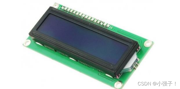
一. LCD1602显示
1.1 简介
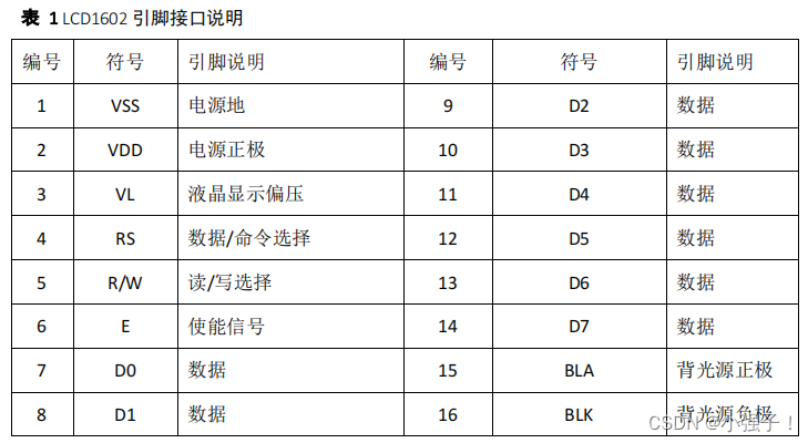
这块挑几个重点的讲解:
- 第 4 脚:RS 为寄存器选择,高电平时选择数据寄存器、低电平时选择==指令(选地址)==寄存器。
- 第 5 脚:R/W 为读写信号线,高电平时进行读操作,低电平时进行写操作。当 RS 和 R/W 共同为低电平时可以写入指令或者显示地址,当 RS 为低电平 R/W 为高电平时可以读忙信号,当== RS 为高电平 R/W 为低电平时可以写入数据==。
- 第 6 脚:E 端为使能端,当 E 端由高电平跳变成低电平时,液晶模块执行命令。
- 指令 9:读忙信号和光标地址。 BF:为忙标志位,高电平表示忙,此时模块不能接收命令或
者数据,如果为低电平表示不忙。
| RS | R/W | 操作 |
|---|---|---|
| 低电平 | 低电平 | 写入指令或显示地址 |
| 低电平 | 高电平 | 读忙信号 |
| 高电平 | 低电平 | 写入数据 |
1.2 开发过程
该模块我们需要弄清楚两件事情:1.在哪显示 2.显示什么
- 在哪显示
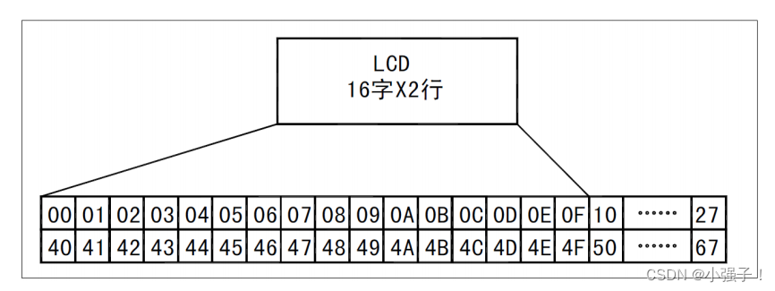
例如第二行第一个字符的地址是 40H,那么是否直接写入 40H 就可以将光标定位在第二行第一个字符的位置呢?
这样不行,因为==写入显示地址时要求最高位 D7 恒定为高电平 1 ==所以实际写入的数据应该是 01000000B(40H) +10000000B(80H)=11000000B(C0H)

- 显示什么
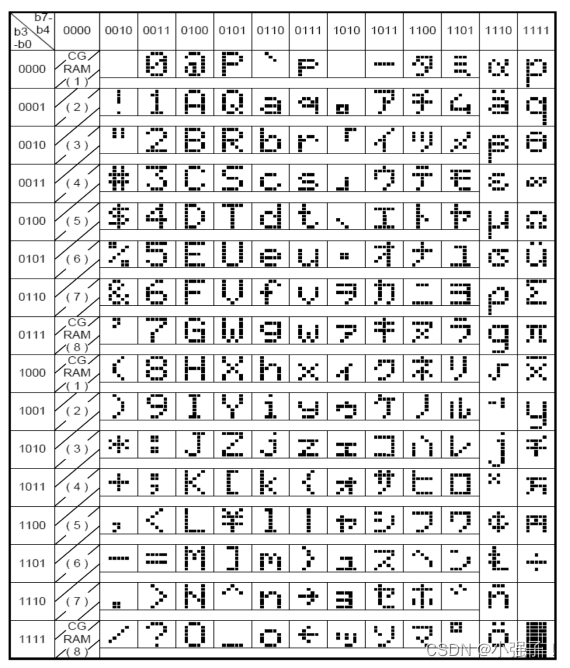
其实本质就是ASII码。
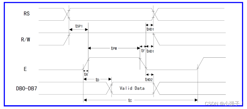
1.2 读写时序
RS=1–数据(内容) RS=0–指令(地址)
读操作时序
写操作
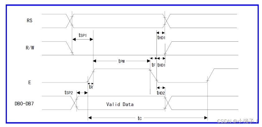
- 写指令代码
void Write_Cmd_Func(char cmd)
{
	RS = 0;
	RW = 0;

	EN = 0;
	_nop_();
	databuffer = cmd;
	EN = 1;
	_nop_();
	_nop_();
	EN = 0;
	_nop_();
}
- 写数据代码
void Write_Data_Func(char dataShow)
{
	RS = 1;
	RW = 0;

	EN = 0;
	_nop_();
	databuffer = dataShow;
	EN = 1;
	_nop_();
	_nop_();
	EN = 0;
	_nop_();
}
1.3 显示一个字符
#include <reg52.h>
#include <intrins.h>

#define databuffer P0
sbit RS = P1^0;
sbit RW = P1^1;
sbit EN = P1^4;

void Write_Cmd_Func(char cmd)
{
	RS = 0;
	RW = 0;

	EN = 0;
	_nop_();
	databuffer = cmd;
	EN = 1;
	_nop_();
	_nop_();
	EN = 0;
	_nop_();
}

void Write_Data_Func(char dataShow)
{
	RS = 1;
	RW = 0;

	EN = 0;
	_nop_();
	databuffer = dataShow;
	EN = 1;
	_nop_();
	_nop_();
	EN = 0;
	_nop_();
}

void Delay15ms() //@11.0592MHz
{
	unsigned char i, j;
	i = 27;
	j = 226;
	do
	{
			while (--j);
	} while (--i);
}
void Delay5ms() //@11.0592MHz
{
	unsigned char i, j;
	i = 9;
	j = 244;
	do
	{
			while (--j);
	} while (--i);
}

void LCD1602_INIT()
{
	//(1)延时 15ms
	Delay15ms();
	//(2)写指令 38H(不检测忙信号)
	Write_Cmd_Func(0x38);
	//(3)延时 5ms
	Delay5ms();
	//(4)以后每次写指令,读/写数据操作均需要检测忙信号
	//(5)写指令 38H:显示模式设置
	Write_Cmd_Func(0x38);
	//(6)写指令 08H:显示关闭
	Write_Cmd_Func(0x08);
	//(7)写指令 01H:显示清屏
	Write_Cmd_Func(0x01);
	//(8)写指令 06H:显示光标移动设置
	Write_Cmd_Func(0x06);
	//(9)写指令 0CH:显示开及光标设置}
	Write_Cmd_Func(0x0c);

}

void main()
{
	char pposition = 0x80 + 0x05;//0x80为硬件要求必加的
	char dataShow = 'C';

	Write_Cmd_Func(pposition);//选择要显示的地址
	Write_Data_Func(dataShow);//发送要显示的字符

}
1.4 检测忙信号(读数据)


void check_busy()
{
	char tmp = 0x80;
	databuffer = 0x80;
	while(tmp & 0x80){ //
		RS = 0;
		RW = 1;

		EN = 0;
		_nop_();
		EN = 1;
		_nop_();
		_nop_();
		tmp = databuffer;
		EN = 0;
		_nop_();
	}
}
完整代码:
#include <reg52.h>
#include <intrins.h>

#define databuffer P0
sbit RS = P1^0;
sbit RW = P1^1;
sbit EN = P1^4;

void check_busy()
{
	//这是硬件检测端口  硬件改变 ,就会变 只是刚开始是0x80
	char tmp = 0x80;
	databuffer = 0x80;
	while(tmp & 0x80){ //
		RS = 0;
		RW = 1;

		EN = 0;
		_nop_();
		EN = 1;
		_nop_();
		_nop_();
		tmp = databuffer;
		EN = 0;
		_nop_();
	}
}

void Write_Cmd_Func(char cmd)
{
	check_busy();
	RS = 0;
	RW = 0;

	EN = 0;
	_nop_();
	databuffer = cmd;
	EN = 1;
	_nop_();
	_nop_();
	EN = 0;
	_nop_();
}

void Write_Data_Func(char dataShow)
{
	check_busy();
	RS = 1;
	RW = 0;

	EN = 0;
	_nop_();
	databuffer = dataShow;
	EN = 1;
	_nop_();
	_nop_();
	EN = 0;
	_nop_();
}

void Delay15ms() //@11.0592MHz
{
	unsigned char i, j;
	i = 27;
	j = 226;
	do
	{
			while (--j);
	} while (--i);
}
void Delay5ms() //@11.0592MHz
{
	unsigned char i, j;
	i = 9;
	j = 244;
	do
	{
			while (--j);
	} while (--i);
}

void LCD1602_INIT()
{
	//(1)延时 15ms
	Delay15ms();
	//(2)写指令 38H(不检测忙信号)
	Write_Cmd_Func(0x38);
	//(3)延时 5ms
	Delay5ms();
	//(4)以后每次写指令,读/写数据操作均需要检测忙信号
	check_busy();
	//(5)写指令 38H:显示模式设置
	Write_Cmd_Func(0x38);
	//(6)写指令 08H:显示关闭
	Write_Cmd_Func(0x08);
	//(7)写指令 01H:显示清屏
	Write_Cmd_Func(0x01);
	//(8)写指令 06H:显示光标移动设置
	Write_Cmd_Func(0x06);
	//(9)写指令 0CH:显示开及光标设置}
	Write_Cmd_Func(0x0c);

}

void main()
{
	char pposition = 0x80 + 0x05;//0x80为硬件要求必加的
	char dataShow = 'C';

	LCD1602_INIT();
	Write_Cmd_Func(pposition);//选择要显示的地址
	Write_Data_Func(dataShow);//发送要显示的字符

}
1.5 显示一行
#include <reg52.h>
#include <intrins.h>

#define databuffer P0
sbit RS = P1^0;
sbit RW = P1^1;
sbit EN = P1^4;

void check_busy()
{
	char tmp = 0x80;
	databuffer = 0x80;

	while(tmp & 0x80){ //
		RS = 0;
		RW = 1;

		EN = 0;
		_nop_();
		EN = 1;
		_nop_();
		_nop_();
		tmp = databuffer;
		EN = 0;
		_nop_();
	}
}

void Write_Cmd_Func(char cmd)
{
	check_busy();
	RS = 0;
	RW = 0;

	EN = 0;
	_nop_();
	databuffer = cmd;
	EN = 1;
	_nop_();
	_nop_();
	EN = 0;
	_nop_();
}

void Write_Data_Func(char dataShow)
{
	check_busy();
	RS = 1;
	RW = 0;

	EN = 0;
	_nop_();
	databuffer = dataShow;
	EN = 1;
	_nop_();
	_nop_();
	EN = 0;
	_nop_();
}

void Delay15ms() //@11.0592MHz
{
	unsigned char i, j;
	i = 27;
	j = 226;
	do
	{
			while (--j);
	} while (--i);
}
void Delay5ms() //@11.0592MHz
{
	unsigned char i, j;
	i = 9;
	j = 244;
	do
	{
			while (--j);
	} while (--i);
}

void LCD1602_INIT()
{
	//(1)延时 15ms
	Delay15ms();
	//(2)写指令 38H(不检测忙信号)
	Write_Cmd_Func(0x38);
	//(3)延时 5ms
	Delay5ms();
	//(4)以后每次写指令,读/写数据操作均需要检测忙信号
	check_busy();
	//(5)写指令 38H:显示模式设置
	Write_Cmd_Func(0x38);
	//(6)写指令 08H:显示关闭
	Write_Cmd_Func(0x08);
	//(7)写指令 01H:显示清屏
	Write_Cmd_Func(0x01);
	//(8)写指令 06H:显示光标移动设置
	Write_Cmd_Func(0x06);
	//(9)写指令 0CH:显示开及光标设置}
	Write_Cmd_Func(0x0c);

}

void LCD1602_showLine(char row,char col,char *string)
{
	switch(row){
		case 1:
			Write_Cmd_Func(0x80 + col);
			while(*string){
				Write_Data_Func(*string);
				string++;
			}
			break;
		case 2:
			Write_Cmd_Func(0x80 + 0x40 + col);
			while(*string){
				Write_Data_Func(*string);
				string++;
			}
			break;
	}
}

void main()
{
	LCD1602_INIT();
	LCD1602_showLine(1,5,"NO.1");
	LCD1602_showLine(2,0,"jiayou");

}
二. DHT11温湿度传感器
2.1 简介
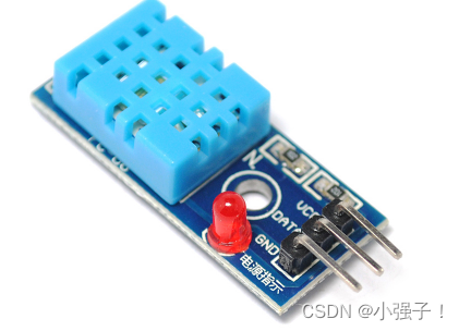
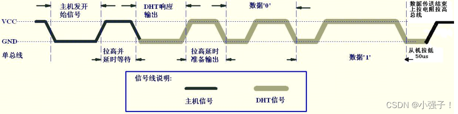
- 数据传送逻辑
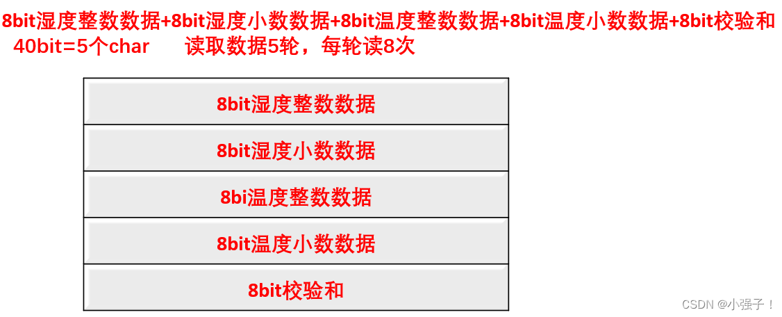
只有一根数据线DATA,上官一号发送序列指令给DHT11模块,模块一次完整的数据传输为40bit,高位先
出 - 数据格式
8bit湿度整数数据+8bit湿度小数数据+8bi温度整数数据+8bit温度小数数据+8bit校验和
2.2 检测模块是否存在
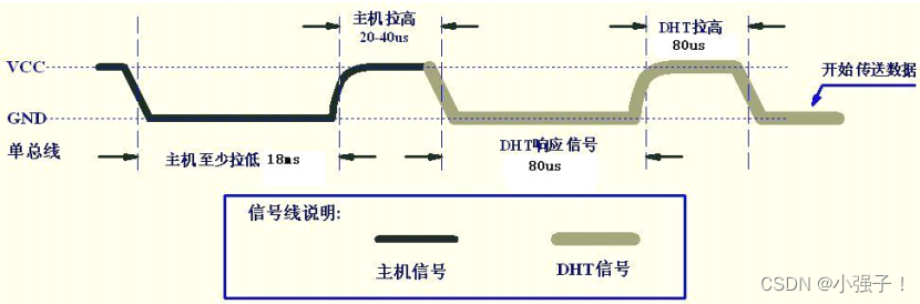
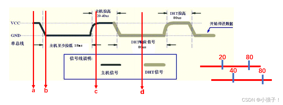
a : dht = 1
b :dht = 0
延时30ms
c: dht = 1
在60us后读d点,如果d点是低电平(被模块拉低),说明模块存在!
void check_DTH()
{
//	a : dht = 1
	dht = 1;
//	b :dht = 0
	dht = 0;
//	延时30ms
	Delay30ms();
//	c: dht = 1
	dht = 1;
//	在60us后读d点,如果d点是低电平(被模块拉低),说明模块存在!
	Delay60us();
	if(dht == 0){
		led1 = 0;//亮灯,说明模块存在
	}
}
使用led灯显示是否存在模块
#include <reg52.h>
#include <intrins.h>

sbit led1 = P3^7;
sbit dht = P3^3;//模块的data插在p3.3

void Delay30ms() //@11.0592MHz
{
	unsigned char i, j;
	i = 54;
	j = 199;
	do
	{
			while (--j);
	} while (--i);
}
void Delay60us() //@11.0592MHz
{
	unsigned char i;
	i = 25;
	while (--i);
}
void Delay1000ms() //@11.0592MHz
{
	unsigned char i, j, k;
	_nop_();
	i = 8;
	j = 1;
	k = 243;
	do
	{
		do
		{
				while (--k);
		} while (--j);
	} while (--i);
}
void check_DTH()
{
//	a : dht = 1
	dht = 1;
//	b :dht = 0
	dht = 0;
//	延时30ms
	Delay30ms();
//	c: dht = 1
	dht = 1;
//	在60us后读d点,如果d点是低电平(被模块拉低),说明模块存在!
	Delay60us();
	if(dht == 0){
		led1 = 0;//亮灯,说明模块存在
	}
}

void main()
{
	led1 = 1;
	Delay1000ms();
	Delay1000ms();
	check_DTH();
	while(1);
}
2.3 读取数据时序
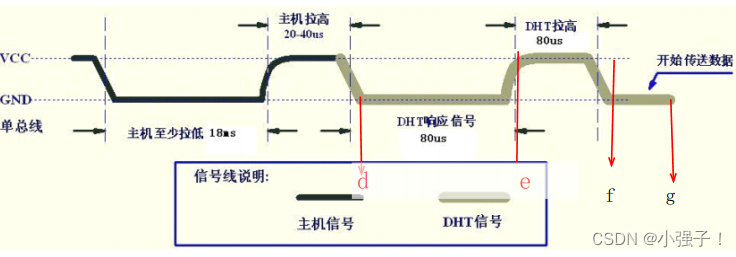
卡d点;while(dht1);
卡e点 while(!dht)
卡f点:while(dht)
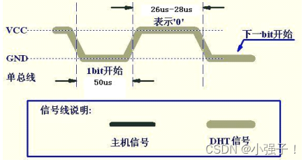
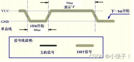
卡g点:while(!dht) 有效数据都是高电平,持续时间不一样,50us读,低电平0 高电平
DHT11传输0的时序分析
DHT11传输1的时序分析
2.4 时序代码
#include <reg52.h>
#include <intrins.h>

sbit led1 = P3^7;
sbit dht = P3^3;//模块的data插在p3.3

char datas[5];

void Delay30ms() //@11.0592MHz
{
	unsigned char i, j;
	i = 54;
	j = 199;
	do
	{
			while (--j);
	} while (--i);
}
void Delay60us() //@11.0592MHz
{
	unsigned char i;
	i = 25;
	while (--i);
}
void Delay1000ms() //@11.0592MHz
{
	unsigned char i, j, k;
	_nop_();
	i = 8;
	j = 1;
	k = 243;
	do
	{
		do
		{
				while (--k);
		} while (--j);
	} while (--i);
}
void DHT11_Start()
{
//	a : dht = 1
	dht = 1;
//	b :dht = 0
	dht = 0;
//	延时30ms
	Delay30ms();
//	c: dht = 1
	dht = 1;
//	卡d点;while(dht1);
	while(dht);
//	卡e点 while(!dht)
	while(!dht)
//	卡f点:while(dht)
	while(dht);
}

void Read_Data_From_DHT()
{
	int i;//轮
	int j;//每一轮多少次
	char tmp;
	char flag;

	DHT11_Start();
	for(i=0;i<5;i++){
		//卡g点:while(!dht) 有效数据都是高电平,持续时间不一样,50us读,低电平0 高电平
		for(j=0;j<8;j++){
			while(!dht);//等待卡g点
			Delay60us();
			if(dht == 1){
				flag = 1;
				while(dht);
			}else{
				flag = 0;
			}
			tmp = tmp << 1;
			tmp |= flag;
		}
		datas[i] = tmp;
	}
}

void main()
{
	led1 = 1;
	Delay1000ms();
	Delay1000ms();
	while(1){
		Delay1000ms();
		Read_Data_From_DHT();
	}
}
2.5 结合串口查看数据
#include "reg52.h"
#include "intrins.h"

sbit ledOne = P3^7;
sbit dht = P3^3;//模块的data插在p3.3

char datas[5];


sfr AUXR = 0x8E;

void UartInit(void)		//9600bps@11.0592MHz
{
	AUXR = 0x01;
	SCON = 0x40; //配置串口工作方式1,REN不使能接收
	TMOD &= 0xF0;
	TMOD |= 0x20;//定时器1工作方式位8位自动重装

	TH1 = 0xFD;
	TL1 = 0xFD;//9600波特率的初值
	TR1 = 1;//启动定时器
}
void sendByte(char data_msg)
{
	SBUF = data_msg;
	while(!TI);
	TI = 0;
}

void sendString(char* str)
{
	while( *str != '\0'){
		sendByte(*str);
		str++;
	}
}

void Delay30ms()		//@11.0592MHz
{
	unsigned char i, j;

	i = 54;
	j = 199;
	do
	{
		while (--j);
	} while (--i);
}

void Delay60us()		//@11.0592MHz
{
	unsigned char i;

	i = 25;
	while (--i);
}

void Delay1000ms()		//@11.0592MHz
{
	unsigned char i, j, k;

	_nop_();
	i = 8;
	j = 1;
	k = 243;
	do
	{
		do
		{
			while (--k);
		} while (--j);
	} while (--i);
}

void DHT11_Start()
{
	dht = 1;
	dht = 0;
	//延时30ms
	Delay30ms();
	dht = 1;
	//卡d点;while(dht1); 卡e点 while(!dht) 卡f点:while(dht)
	while(dht);
	while(!dht);
	while(dht);
}
void Delay40us()		//@11.0592MHz
{
	unsigned char i;

	_nop_();
	i = 15;
	while (--i);
}

void Read_Data_From_DHT()
{
	int i;//轮
	int j;//每一轮读多少次
	char tmp;
	char flag;

	DHT11_Start();
	for(i= 0;i < 5;i++){
		//卡g点:while(!dht)       有效数据都是高电平,持续时间不一样,50us读,低电平0 高电平
		for(j=0;j<8;j++){
			while(!dht);//等待卡g点
			Delay40us();
			if(dht == 1){
				flag = 1;
				while(dht);
			}else{
				flag = 0;
			}
			tmp = tmp << 1;
			tmp |= flag;
		}
		datas[i] = tmp;
	}

}

void main()
{
	ledOne = 1;
	UartInit();
	Delay1000ms();
	Delay1000ms();
	while(1){
		Delay1000ms();
		Read_Data_From_DHT();
		sendString("H:");
		sendByte(datas[0]/10 + 0x30);//43 a
		sendByte(datas[0]%10 + 0x30);
		sendByte('.');
		sendByte(datas[1]/10 + 0x30);//43 a
		sendByte(datas[1]%10 + 0x30);
		sendString("\r\n");
		sendString("T:");
		sendByte(datas[2]/10 + 0x30);//43 a
		sendByte(datas[2]%10 + 0x30);
		sendByte('.');
		sendByte(datas[3]/10 + 0x30);//43 a
		sendByte(datas[3]%10 + 0x30);
		sendString("\r\n");
	}
}
2.6 结合蓝牙模块和LCD1602模块显示温湿度
#include "reg52.h"
#include "intrins.h"

sbit ledOne = P3^7;
sbit dht = P3^3;//模块的data插在p3.3
sbit fengshan = P1^6;
char datas[5];


sfr AUXR = 0x8E;
#define databuffer  P0 //定义8位数据线,Po端口组
sbit RS = P1^0;
sbit RW = P1^1;
sbit EN = P1^4;
char temp[8];
char huma[8];

void check_busy()
{
	char tmp = 0x80;
	databuffer = 0x80;

	while(tmp & 0x80){//1000 0000
		RS = 0;
		RW = 1;
		EN = 0;
		_nop_();
		EN = 1;
		_nop_();
		_nop_();
		tmp = databuffer;
		EN = 0;
		_nop_();
	}
}

void Write_Cmd_Func(char cmd)
{
	check_busy();
	RS = 0;
	RW = 0;

	EN = 0;
	_nop_();
	databuffer = cmd;
	_nop_();
	EN = 1;
	_nop_();
	_nop_();
	EN = 0;
	_nop_();
}

void Write_Data_Func(char dataShow)
{
	check_busy();
	RS = 1;
	RW = 0;

	EN = 0;
	_nop_();
	databuffer = dataShow;
	_nop_();
	EN = 1;
	_nop_();
	_nop_();
	EN = 0;
	_nop_();
}

void Delay15ms()		//@11.0592MHz
{
	unsigned char i, j;

	i = 27;
	j = 226;
	do
	{
		while (--j);
	} while (--i);
}
void Delay5ms()		//@11.0592MHz
{
	unsigned char i, j;

	i = 9;
	j = 244;
	do
	{
		while (--j);
	} while (--i);
}

void UartInit(void)		//9600bps@11.0592MHz
{
	AUXR = 0x01;
	SCON = 0x40; //配置串口工作方式1,REN不使能接收
	TMOD &= 0xF0;
	TMOD |= 0x20;//定时器1工作方式位8位自动重装

	TH1 = 0xFD;
	TL1 = 0xFD;//9600波特率的初值
	TR1 = 1;//启动定时器
}
void sendByte(char data_msg)
{
	SBUF = data_msg;
	while(!TI);
	TI = 0;
}

void sendString(char* str)
{
	while( *str != '\0'){
		sendByte(*str);
		str++;
	}
}

void Delay30ms()		//@11.0592MHz
{
	unsigned char i, j;

	i = 54;
	j = 199;
	do
	{
		while (--j);
	} while (--i);
}

void Delay60us()		//@11.0592MHz
{
	unsigned char i;

	i = 25;
	while (--i);
}

void Delay1000ms()		//@11.0592MHz
{
	unsigned char i, j, k;

	_nop_();
	i = 8;
	j = 1;
	k = 243;
	do
	{
		do
		{
			while (--k);
		} while (--j);
	} while (--i);
}

void DHT11_Start()
{
	dht = 1;
	dht = 0;
	//延时30ms
	Delay30ms();
	dht = 1;
	//卡d点;while(dht1); 卡e点 while(!dht) 卡f点:while(dht)
	while(dht);
	while(!dht);
	while(dht);
}
void Delay40us()		//@11.0592MHz
{
	unsigned char i;

	_nop_();
	i = 15;
	while (--i);
}

void Read_Data_From_DHT()
{
	int i;//轮
	int j;//每一轮读多少次
	char tmp;
	char flag;

	DHT11_Start();
	for(i= 0;i < 5;i++){
		//卡g点:while(!dht)       有效数据都是高电平,持续时间不一样,50us读,低电平0 高电平
		for(j=0;j<8;j++){
			while(!dht);//等待卡g点
			Delay40us();
			if(dht == 1){
				flag = 1;
				while(dht);
			}else{
				flag = 0;
			}
			tmp = tmp << 1;
			tmp |= flag;
		}
		datas[i] = tmp;
	}

}

void LCD1602_INIT()
{
	//(1)延时 15ms
	Delay15ms();
//(2)写指令 38H(不检测忙信号)
	Write_Cmd_Func(0x38);
//(3)延时 5ms
	Delay5ms();
//(4)以后每次写指令,读/写数据操作均需要检测忙信号
//(5)写指令 38H:显示模式设置
	Write_Cmd_Func(0x38);
//(6)写指令 08H:显示关闭
	Write_Cmd_Func(0x08);
//(7)写指令 01H:显示清屏
	Write_Cmd_Func(0x01);
//(8)写指令 06H:显示光标移动设置
	Write_Cmd_Func(0x06);
//(9)写指令 0CH:显示开及光标设置}
	Write_Cmd_Func(0x0c);
}


void LCD1602_showLine(char row, char col, char *string)
{

	switch(row){

		case 1:
				Write_Cmd_Func(0x80+col);
				while(*string){
					Write_Data_Func(*string);
					string++;
				}
				break;

		case 2:
				Write_Cmd_Func(0x80+0x40+col);
				while(*string){
					Write_Data_Func(*string);
					string++;
				}
				break;

	}
}

void Build_Datas()
{
	huma[0] = 'H';
	huma[1] = datas[0]/10 + 0x30;
	huma[2] = datas[0]%10 + 0x30;
	huma[3] = '.';
	huma[4] = datas[1]/10 + 0x30;
	huma[5] = datas[1]%10 + 0x30;
	huma[6] = '%';
	huma[7] = '\0';

	temp[0] = 'T';
	temp[1] = datas[2]/10 + 0x30;
	temp[2] = datas[2]%10 + 0x30;
	temp[3] = '.';
	temp[4] = datas[3]/10 + 0x30;
	temp[5] = datas[3]%10 + 0x30;
	temp[6] = 'C';
	temp[7] = '\0';

}

void main()
{

	Delay1000ms();
	UartInit(); //串口初始化
	LCD1602_INIT();//LCD1602初始化
	Delay1000ms();
	Delay1000ms();
	ledOne = 0;
	while(1){
		Delay1000ms();
		Read_Data_From_DHT();//读取温湿度数据
		if(datas[2] > 24){//datas[2]温度的整数部分
			fengshan = 0;//开风扇
		}
		Build_Datas();//对获取的温湿度数据转化
		sendString(huma);
		sendString("\r\n");
		sendString(temp);
		sendString("\r\n");
		LCD1602_showLine(1,2,huma);//在LCD1602上显示
		LCD1602_showLine(2,2,temp);
	}
}


 643
643


 被折叠的 条评论
为什么被折叠?
被折叠的 条评论
为什么被折叠?
 到【灌水乐园】发言


