


参考文献:Cortex-M3权威指南(中文)第5.5章
STM32中文参考手册_V10第2.3.2章
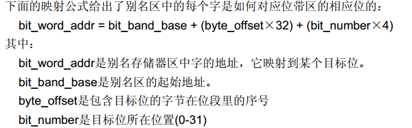
位线操作是把寄存器中的某个位单独拿出来,放在位带区,并且在位带别名区重新膨胀为1个字,但只能对这个位进行操作。通过访问位带别名区来访问某个单独的位。
位带区的每一个位都是通过对位带别名区的地址来访问。位带区一个位,对应位带别名区一个字(即4个字节)
在 CM3中,有两个区中实现了位带。其中一个是 SRAM 区的最低 1MB 范围,第二个则是片内外设区的最低 1MB 范围。但ST公司设计的芯片只使用了64KB。
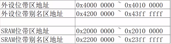
通过查看存储器印象表,我们发现外设地址是0x00000000到0x4002 9FFF,其余是保留的。所以,可以认为,我们以前操作的都是位带区,现在,我们把每一个位都变成1个字,膨胀了32倍之后,放到位带别名区,这样,访问一个别名区的地址,就是在访问一个位的地址。

代码是在上一个的基础上改的,所以不写注释了,见前一个文章的注释
main.c
#include "stm32f10x.h"
#include "led.h"
#include "key.h"
int main()
{
	LED_GPIO_Config();
	KEY_GPIO_Config();

#if 0
	while(1)
	{
		LED1=1;
		delay(0x100000);
		LED1=0;
		delay(0x100000);
	}


#elif 1
	while(1)
	{
		if(KEY1_2_GPIO_in(0)==KEY_ON)
		{
		   while(KEY1_2_GPIO_in(0)==KEY_ON)
		   ;
		   	LED_GH1;
		}
		if(KEY1_2_GPIO_in(8)==KEY_ON)
		{
		   while(KEY1_2_GPIO_in(8)==KEY_ON)
		   ;
		   	LED_GH2;
		}
		if(KEY3_4_GPIO_in(1)==KEY_ON)
		{
		   while(KEY3_4_GPIO_in(1)==KEY_ON)
		   ;
		   	LED_GH3;
		}
		if(KEY3_4_GPIO_in(2)==KEY_ON)
		{
		   while(KEY3_4_GPIO_in(2)==KEY_ON)
		   ;
		   	LED_GH4;
		}
	}
#endif
}
led.h
#ifndef	 _LED_H
#define  _LED_H
#include "stm32f10x.h"
#define ON  0
#define OFF 1

#define LED_G(a)   if(a) \
                          GPIO_SetBits(LED0_GPIO_PORT,LED0_GPIO_Pin);\
                   else   GPIO_ResetBits(LED0_GPIO_PORT,LED0_GPIO_Pin);
#define LED0_GPIO_Pin    GPIO_Pin_8
#define LED1_GPIO_Pin    GPIO_Pin_9
#define LED2_GPIO_Pin    GPIO_Pin_10
#define LED3_GPIO_Pin    GPIO_Pin_11
#define LED0_GPIO_PORT   GPIOC
#define LED1_GPIO_PORT   GPIOC
#define LED2_GPIO_PORT   GPIOC
#define LED3_GPIO_PORT   GPIOC
#define LED_GH1   (LED0_GPIO_PORT->ODR^=LED0_GPIO_Pin)
#define LED_GH2   (LED1_GPIO_PORT->ODR^=LED1_GPIO_Pin)
#define LED_GH3   (LED2_GPIO_PORT->ODR^=LED2_GPIO_Pin)
#define LED_GH4   (LED3_GPIO_PORT->ODR^=LED3_GPIO_Pin)
#define LED0_GPIO_CLK    RCC_APB2Periph_GPIOC
#define LED_GPIO_Out(n)       *(unsigned int*)(0x42000000+0x1100C*32+n*4)//基址+(外设偏移+寄存器偏移)*32+位偏移*4
#define LED1 	 LED_GPIO_Out(8)
#define LED2 	 LED_GPIO_Out(9)
#define LED3 	 LED_GPIO_Out(10)
#define LED4 	 LED_GPIO_Out(11)
void LED_GPIO_Config(void);
void delay(uint32_t time);
#endif
led.c
#include "led.h"

void LED_GPIO_Config(void)
{
	GPIO_InitTypeDef GPIO_InitStruct1;
	GPIO_InitTypeDef GPIO_InitStruct2;
	GPIO_InitTypeDef GPIO_InitStruct3;
	GPIO_InitTypeDef GPIO_InitStruct4;
	RCC_APB2PeriphClockCmd(RCC_APB2Periph_GPIOC, ENABLE);

	GPIO_InitStruct1.GPIO_Pin=  LED0_GPIO_Pin;
	GPIO_InitStruct1.GPIO_Mode= GPIO_Mode_Out_PP;
	GPIO_InitStruct1.GPIO_Speed=GPIO_Speed_50MHz;
	GPIO_Init(LED0_GPIO_PORT,&GPIO_InitStruct1);

	GPIO_InitStruct2.GPIO_Pin=  LED1_GPIO_Pin;
	GPIO_InitStruct2.GPIO_Mode= GPIO_Mode_Out_PP;
	GPIO_InitStruct2.GPIO_Speed=GPIO_Speed_50MHz;
	GPIO_Init(LED1_GPIO_PORT,&GPIO_InitStruct2);

	GPIO_InitStruct3.GPIO_Pin=  LED2_GPIO_Pin;
	GPIO_InitStruct3.GPIO_Mode= GPIO_Mode_Out_PP;
	GPIO_InitStruct3.GPIO_Speed=GPIO_Speed_50MHz;
	GPIO_Init(LED2_GPIO_PORT,&GPIO_InitStruct3);

	GPIO_InitStruct4.GPIO_Pin=  LED3_GPIO_Pin;
	GPIO_InitStruct4.GPIO_Mode= GPIO_Mode_Out_PP;
	GPIO_InitStruct4.GPIO_Speed=GPIO_Speed_50MHz;
	GPIO_Init(LED3_GPIO_PORT,&GPIO_InitStruct4);

}
void delay(uint32_t time)
{
	while(time--)
	;
}
key.h
#ifndef	 _KEY_H
#define  _KEY_H
#include "stm32f10x.h"
#include "led.h"

#define KEY_ON  0
#define KEY_OFF 1
#define KEY1_GPIO_Pin    GPIO_Pin_0
#define KEY2_GPIO_Pin    GPIO_Pin_8
#define KEY3_GPIO_Pin    GPIO_Pin_1
#define KEY4_GPIO_Pin    GPIO_Pin_2
#define KEY1_GPIO_PORT   GPIOA
#define KEY2_GPIO_PORT   GPIOA
#define KEY3_GPIO_PORT   GPIOB
#define KEY4_GPIO_PORT   GPIOB

#define KEY1_2_GPIO_CLK    RCC_APB2Periph_GPIOA
#define KEY3_4_GPIO_CLK    RCC_APB2Periph_GPIOB

#define KEY1_2_GPIO_in(n)       *(unsigned int*)(0x42000000+0x10808*32+n*4)
#define KEY3_4_GPIO_in(n)       *(unsigned int*)(0x42000000+0x10C08*32+n*4)
//基址+(外设偏移+寄存器偏移)*32+位偏移*4


void KEY_GPIO_Config(void);
#endif
key.c
#include"key.h"

void KEY_GPIO_Config(void)
{
	GPIO_InitTypeDef GPIO_InitStruct1;
	GPIO_InitTypeDef GPIO_InitStruct2;
	GPIO_InitTypeDef GPIO_InitStruct3;
	GPIO_InitTypeDef GPIO_InitStruct4;
	RCC_APB2PeriphClockCmd(KEY1_2_GPIO_CLK, ENABLE);
	RCC_APB2PeriphClockCmd(KEY3_4_GPIO_CLK, ENABLE);

	GPIO_InitStruct1.GPIO_Pin=  KEY1_GPIO_Pin;
	GPIO_InitStruct1.GPIO_Mode= GPIO_Mode_IPU;
	GPIO_Init(KEY1_GPIO_PORT,&GPIO_InitStruct1);

	GPIO_InitStruct2.GPIO_Pin=  KEY2_GPIO_Pin;
	GPIO_InitStruct2.GPIO_Mode= GPIO_Mode_IPU;
	GPIO_Init(KEY2_GPIO_PORT,&GPIO_InitStruct2);

	GPIO_InitStruct3.GPIO_Pin=  KEY3_GPIO_Pin;
	GPIO_InitStruct3.GPIO_Mode= GPIO_Mode_IPU;
	GPIO_Init(KEY3_GPIO_PORT,&GPIO_InitStruct3);

	GPIO_InitStruct4.GPIO_Pin=  KEY4_GPIO_Pin;
	GPIO_InitStruct4.GPIO_Mode= GPIO_Mode_IPU;
	GPIO_Init(KEY4_GPIO_PORT,&GPIO_InitStruct4);
}


 148
148


 被折叠的 条评论
为什么被折叠?
被折叠的 条评论
为什么被折叠?
 到【灌水乐园】发言


