


 本文详细介绍了无线通信中UE(用户设备)的最大发射功率及其在不同功率类别下的最大功率减少(MPR)计算。内容涵盖了数学运算、资源块分类、边沿和内部资源块定义,并针对不同信道带宽给出了具体的MPR值。此外,还讨论了额外最大输出功率减少(AMPR)的情况,以及与网络信号相关的参数。内容基于3GPPTS38.101-1V17.4.0标准。
Transmitter Characteristics
1. Transmitter power
1.1 UE maximum output power
1.2 UE maximum output power reduction (MPR)
1. General
Before talking about specifc MPR values in different PCs, let us classify RB types based on RB location.
(1) Firstly, some mathematics operations,
- max() is the largest value of all arguments
- floor(x) is the greatest integer less than or equal to x.
- ceil(x) is the smallest integer greater than or equal to x.
(2) Secondly, some RB locations,
- NRB is the maximum number of RBs for a given Channel bandwidth and sub-carrier spacing.
- LCRB is transmission bandwidth which represents the length of a contiguous resource block allocation expressed in units of resources blocks
- RBStart,Low = max(1, floor(LCRB/2))
- RBStart,High = NRB – RBStart,Low – LCRB
(3) Lastly, Inner/Edge/Outer RB definition,
-
Inner RB allocation
RBStart,Low ≤ RBStart ≤ RBStart,High, and
LCRB ≤ ceil(NRB/2) -
Edge RB allocation
An Edge RB allocation is the one for which the RB(s) is (are) allocated at the lowermost or uppermost edge of the channel with
LCRB ≤ 4 RBs for power class 1.5 and
LCRB ≤ 2 RBs for other power classes. -
Outer RB allocation
The RB allocation is an Outer RB allocation for all other allocations which are not an Inner RB allocation or Edge RB allocation.
2. MPR values in different PCs
For channel bandwidths ≤ 100 MHz,
-
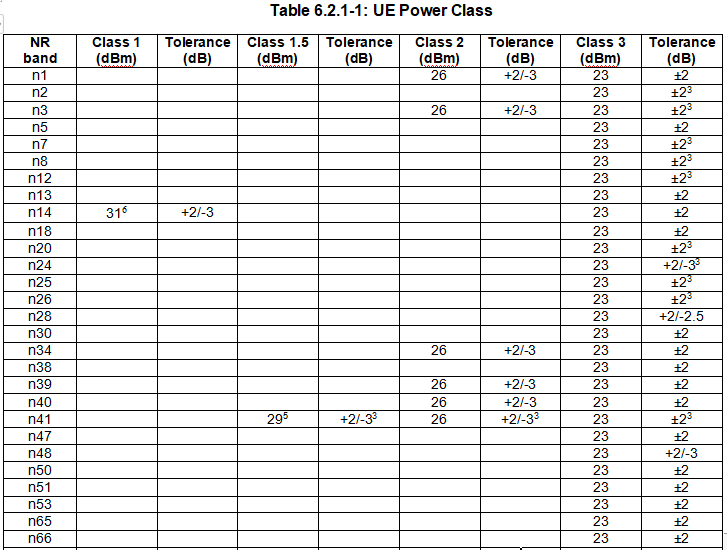
MPR of power class 3 — Table 6.2.2-1
-
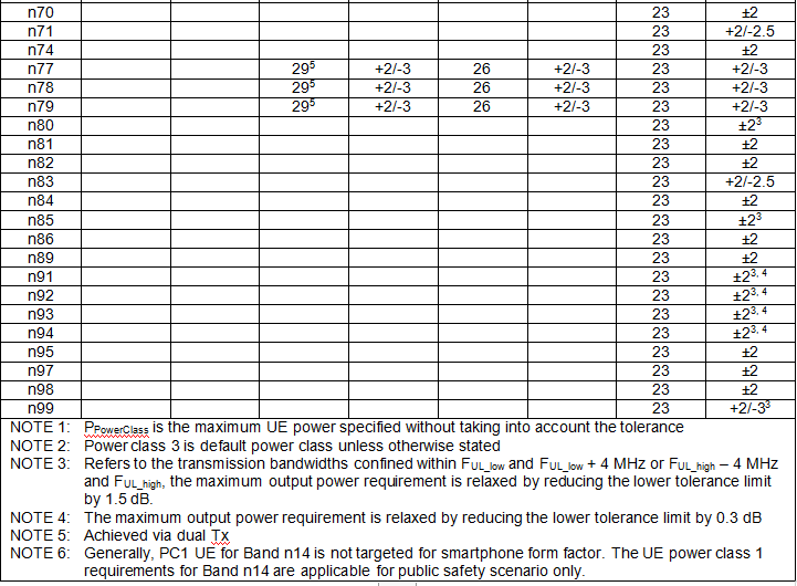
MPR of power class 2 — Table 6.2.2-2
-
∆MPR
-
∆MPR — Table 6.2.2-3
if the relative channel bandwidth > 4% for TDD bands or > 3% for FDD bands -
∆MPR = 0
if the relative channel bandwidth ≤ 4% for TDD bands or ≤ 3% for FDD band, the ∆MPR is set to zeroWhere relative channel bandwidth = 2*BWChannel / (FUL_low + FUL_high)
-
-
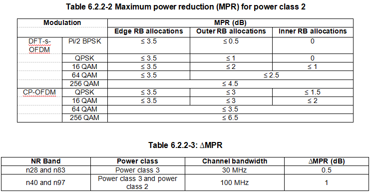
MPR of power class 1.5— Table 6.2.2-4 and Table 6.2.2-4a
-
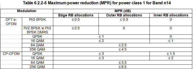
MPR of power class 1 in n14 — Table 6.2.2-5


1.3 UE additional maximum output power reduction (AMPR)
Each additional emission requirement is associated with a unique network signalling (NS) value indicated in RRC signalling by an NR frequency band number of the applicable operating band and an associated value in the field additionalSpectrumEmission.
the total reduction to UE maximum output power is max(MPR, A-MPR)
1. A-MPR for NS_04
For NS_04, A-MPR is not added to MPR. Also, when NS_04 is signalled, MPR shall be set to zero in the PCMAX equations to avoid double counting MPR. Allowed maximum power reduction is defined as A-MPR = max(MPR, A-MPR’), Note that A-MPR’ = 0 dB means only MPR is applied, where A-MPR’ is defined as
- if
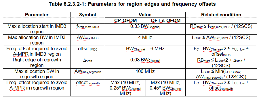
RBstart ≤ fstart,max,IMD3 / (12SCS) and
LCRB ≤ AWmax,IMD3 / (12SCS) and
FC - BWChannel/2 < FUL_low + offsetIMD3,
then
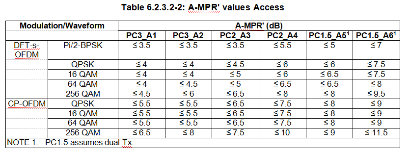
the A-MPR’ is defined according to Table 6.2.3.2-2
PC3_A2 relative to 23 dBm for power class 3,
PC2_A4 relative to 26 dBm for power class 2,
and PC1.5_A6 relative to 29 dBm for power class 1.5, - else,if
RBstart ≤ LCRB/2 + deltastart / (12SCS) and
LCRB ≤ AWmax,regrowth / (12SCS) and
FC - BWChannel/2 < FUL_low + offsetregrowth,
then
the A-MPR’ is defined according to Table 6.2.3.2-2
PC3_A1 relative to 23 dBm for power class 3,
PC2_A3 relative to 26 dBm for power class 2,
and PC1.5_A5 relative to 29 dBm for power class 1.5, - else
A-MPR’ = 0 dB and apply MPR.
With the parameters defined in Table 6.2.3.2-1.
1.4 Configured transmitted power
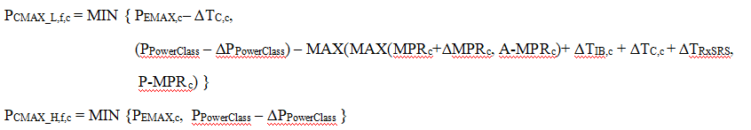
The UE is allowed to set its configured maximum output power PCMAX,f,c for carrier f of serving cell c in each slot. The configured maximum output power PCMAX,f,c is set within the following bounds:
PCMAX_L,f,c ≤ PCMAX,f,c ≤ PCMAX_H,f,c with
Reference
[1] 3GPP TS 38.101-1 V17.4.0 (2021-12)


 3957
3957

 被折叠的 条评论
为什么被折叠?
被折叠的 条评论
为什么被折叠?
 到【灌水乐园】发言


