


覆盖栅格建图算法的实现
文章参考了机器人学习–栅格地图(occupancy grid map)构建(部分代码解析)
前言
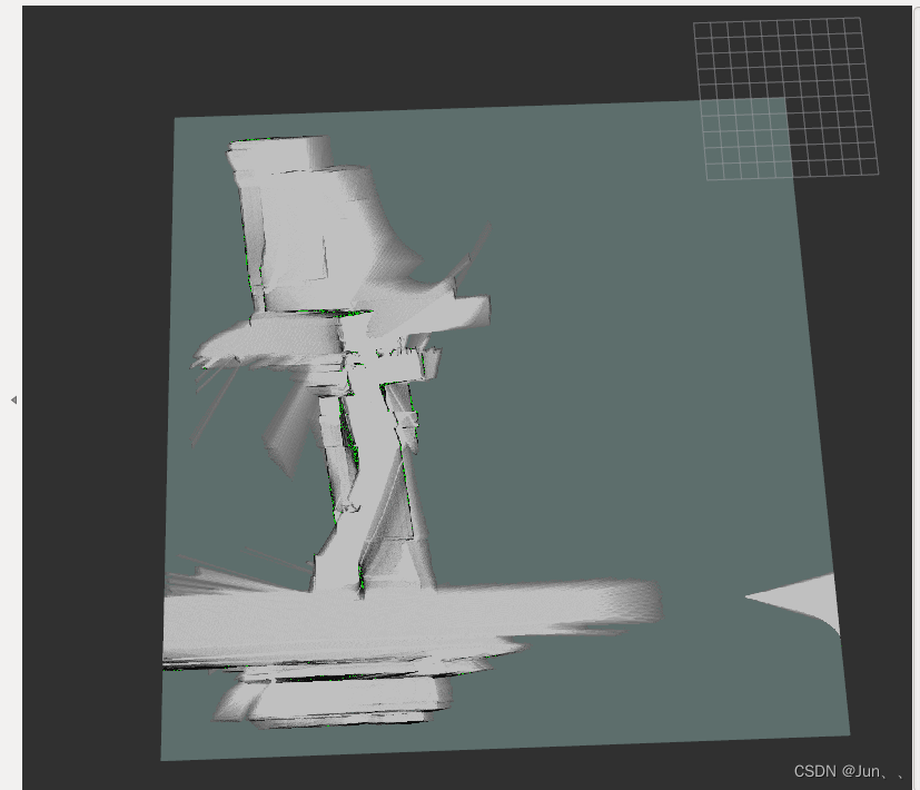
在完成深蓝学院激光SLAM课程第七章——基于已知建图的算法过程中,根据栅格建图算法实现建图。但是建图效果不理想,出现以下问题:建图效果不理想,边缘特征不明显。
一、基于已知建图的算法
改进前的算法:
//占据栅格地图
void OccupanyMapping(std::vector<GeneralLaserScan>& scans,std::vector<Eigen::Vector3d>& robot_poses)
{
    //枚举所有的激光雷达数据
    for(int i = 0; i < scans.size();i++)
    {
        GeneralLaserScan scan = scans[i];
        Eigen::Vector3d robotPose = robot_poses[i];

        //机器人的下标robotIndex
        //从世界坐标系到栅格坐标系
        //robotPose的[x,y,z]中的[x,y](也就是下面的robotPose(0),robotPose(1))
        GridIndex robotIndex = ConvertWorld2GridIndex(robotPose(0),robotPose(1));

        for(int id = 0; id < scan.range_readings.size();id++)
        {
            double dist = scan.range_readings[id];  //得到该帧激光雷达的距离
            double angle = scan.angle_readings[id]; //得到该帧激光雷达的角度

            //剔除异常数据,跳过该次循环,不作处理
            if(std::isinf(dist) || std::isnan(dist)) continue;

            //计算得到该激光点的世界坐标系的坐标
            double theta = robotPose(2);    //机器人的航向角
            double laser_x = dist * cos(angle);
            double laser_y = dist * sin(angle);

            double world_x = cos(theta) * laser_x - sin(theta) * laser_y + robotPose(0);
            double world_y = sin(theta) * laser_x + cos(theta) * laser_y + robotPose(1);

            //start of TODO 对对应的map的cell进行更新.
            /*目前已知:1、激光点在世界坐标系的坐标world_x   world_y
                      2、每帧机器人位姿对应栅格地图robotIndex
             */

            //1、将转化后的激光数据再映射到栅格坐标系下去 得到每个激光点的栅格序号Index
            GridIndex laserIndex = ConvertWorld2GridIndex(world_x,world_y);
            //2、判断该激光数据的栅格index是否在设定的900*900的区域內
            if(isValidGridIndex(laserIndex) == false)
                continue;//跳过当前这次循环
            //3、寻找激光点和机器人对应的栅格之间的空闲栅格 将空闲(free)栅格序号存入到freeIndex中
            std::vector<GridIndex> freeIndex = TraceLine(robotIndex.x,robotIndex.y,laserIndex.x,laserIndex.y);

            //4、处理空闲栅格
            for(int i = 0;i < freeIndex.size(); i++)
            {
                GridIndex tmpIndex = freeIndex[i];
                //将空闲栅格的栅格序号,转化到数组序号,该数组用于存储每一个栅格的数据
                int linearIndex = GridIndexToLinearIndex(tmpIndex);
                //得到该空闲栅格的数据(初始默认50)
                int data = pMap[linearIndex];
                if(data>0)
                    data += mapParams.log_free;
                else
                    data = 0;
                pMap[linearIndex] = data;
            }
            //5、处理占据栅格
            if(pMap[GridIndexToLinearIndex(laserIndex)]<100)
                pMap[GridIndexToLinearIndex(laserIndex)] += mapParams.log_occ;
            else
                pMap[GridIndexToLinearIndex(laserIndex)] = 100;
            //end of TODO
        }
    }
}
改进前的建图效果:
二、原因
1、出问题的代码:
double world_y = sin(theta) * laser_x + cos(theta) * laser_y + robotPose(1);
此处world_y中少了一个符号,应改为下面的代码:
double world_y = -(sin(theta) * laser_x + cos(theta) * laser_y) + robotPose(1);
2、原因分析:
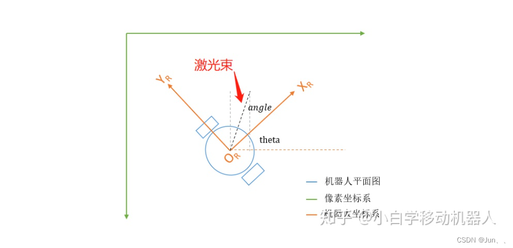
如上图:激光点的坐标是基于当前机器人坐标系的,因此需要将其转化到世界坐标系下。因此才有了代码:
	//计算得到该激光点在世界坐标系的坐标
	double theta = robotPose(2);    //机器人的航向角
	double laser_x = dist * cos(angle);
	double laser_y = dist * sin(angle);

	double world_x = cos(theta) * laser_x - sin(theta) * laser_y + robotPose(0);
	double world_y = sin(theta) * laser_x + cos(theta) * laser_y + robotPose(1);
注:这里的robotPose对应机器人模型(x,y,θ),robotPose(0)是x,robotPose(1)是y
theta是机器人(x,y,θ)中的θ
为什么需要加符号“-”?
原因: 这里的世界坐标系world_x,不是真实的世界坐标系,而是像素坐标系,y轴与真实的世界坐标系相反,这样是laser_y加负号的原因
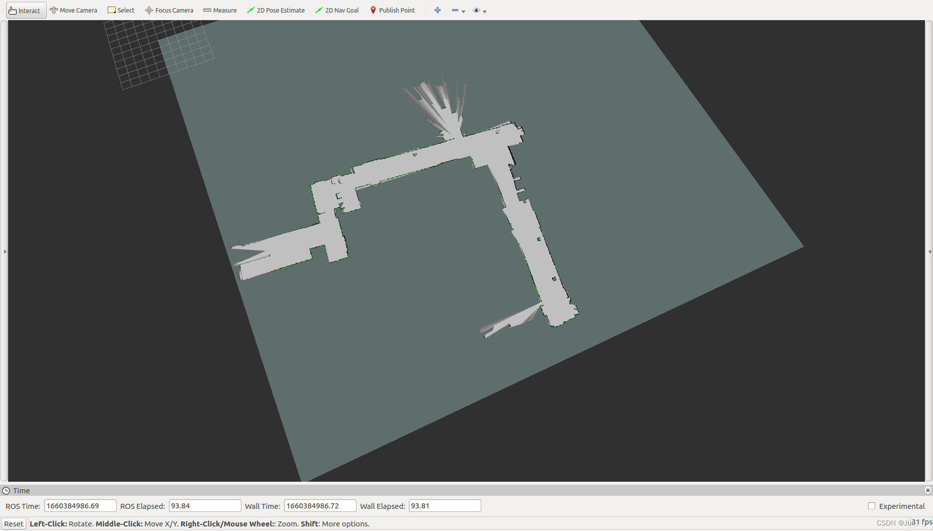
三、改进后的建图效果
修改代码后的效果如下图:


 2278
2278

 被折叠的 条评论
为什么被折叠?
被折叠的 条评论
为什么被折叠?
 到【灌水乐园】发言


