


基于modelsim的verilog仿真提示:文章写完后,目录可以自动生成,如何生成可参考右边的帮助文档
前言
前言:零基础小白探索modelsim-判决电路
一、modelsim创建工程
1.打开modelsim,File-Change directory,选择文件路径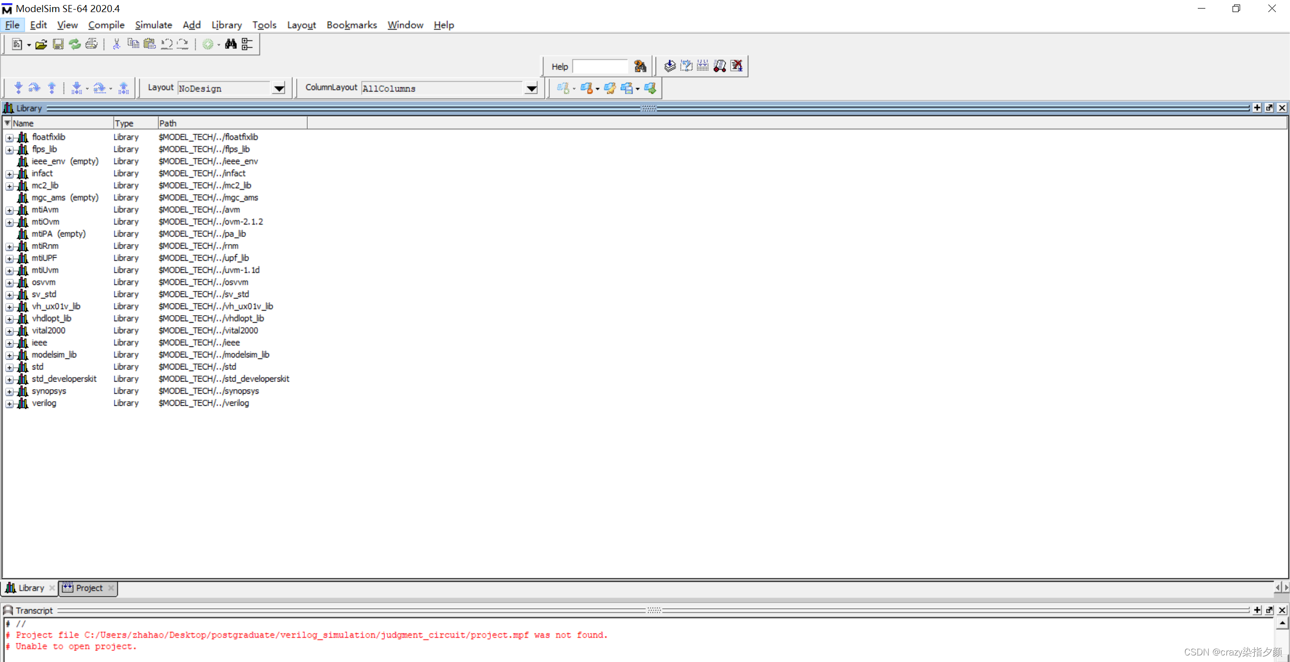
2.点击File-new project将其命名为project,再点击OK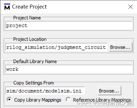
3.点击Create New File,将其命名为judgment_circuit,类型选择verilog,点击ok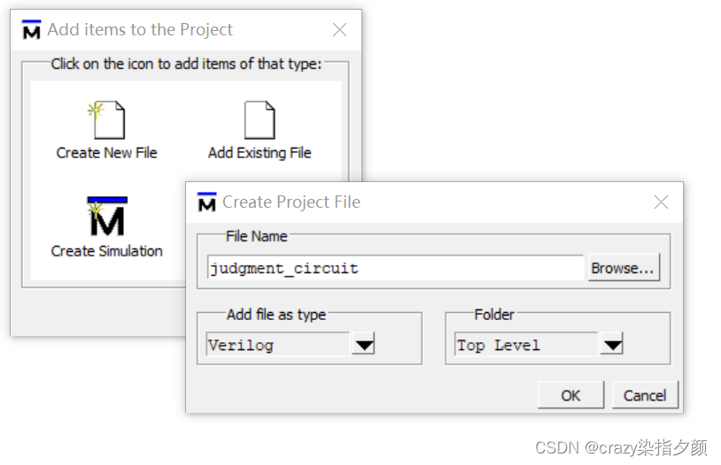
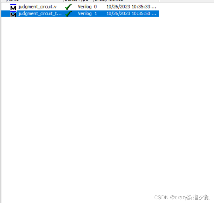
4.同样的操作,创建另一个文件,将其命名为judgment_circuit_tb,用来作为testbench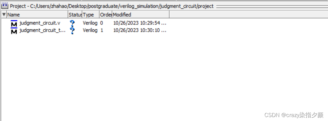
二、使用步骤
1.双击judgment_circuit
代码如下(示例):
module judgment_circuit(
	input wire a,
	input wire b,
	input wire c,
	output reg out
);
	always@(a,b,c)
		case({a,b,c})
			3'b000:out <= 0;
			3'b001:out <= 0;
			3'b010:out <= 0;
			3'b011:out <= 0;
			3'b100:out <= 1;
			3'b101:out <= 1;
			3'b110:out <= 1;
			3'b111:out <= 1;
		endcase
endmodule
2.点击judgment_circuit_tb
代码如下(示例):
`timescale 1ns/1ns
module judgment_tb();
	reg a_tb;
	reg b_tb;
	reg c_tb;
	wire out_tb;
	judgment_circuit u1 (.a(a_tb),.b(b_tb),.c(c_tb),.out(out_tb));
	initial
	begin
		a_tb = 0;
		b_tb = 0;
		c_tb = 0;
		#1000;

		a_tb = 0;
		b_tb = 0;
		c_tb = 1;
		#1000;

		a_tb = 0;
		b_tb = 1;
		c_tb = 0;
		#1000;

		a_tb = 0;
		b_tb = 1;
		c_tb = 1;
		#1000;

		a_tb = 1;
		b_tb = 0;
		c_tb = 0;
		#1000;

		a_tb = 1;
		b_tb = 0;
		c_tb = 1;
		#1000;

		a_tb = 1;
		b_tb = 1;
		c_tb = 0;
		#1000;

		a_tb = 1;
		b_tb = 1;
		c_tb = 1;
		#1000;
	end
endmodule
3.ctrl+s保存,在该页面空白处,鼠标右击选择Compile-Compile All,编译俩个文件
4.界面底部会显示遇到的错误和警告,successful代表编译成功。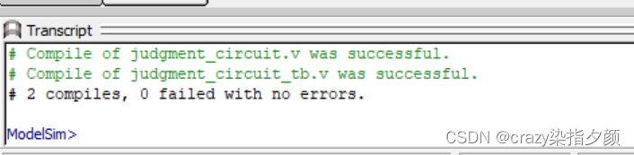
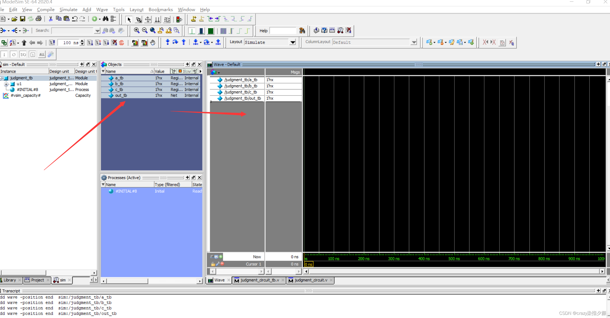
5.点击左下角library,点开work,选择judgment_circuit_tb,右击选择simulate,会出现以下界面。

6.接下来查看波形仿真:点击下面的wave窗口,在objects中选中四个变量,拖拽到wave_default中
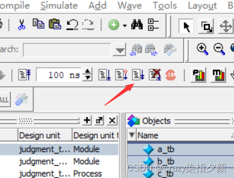
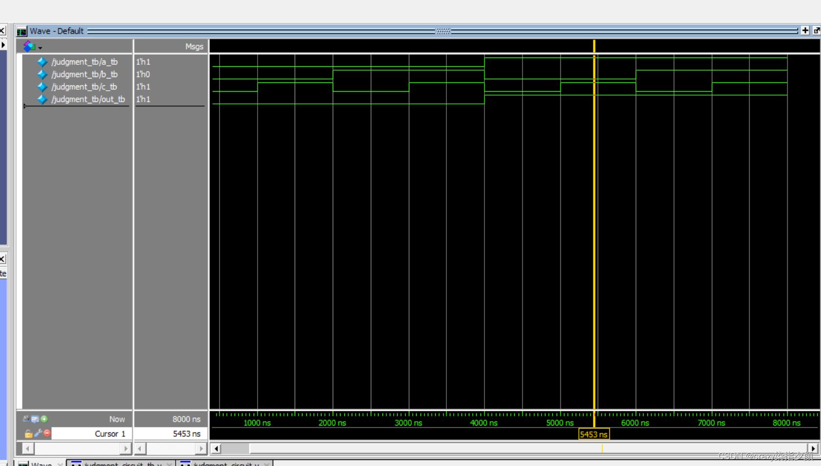
7.点击rull-all
8.波形如图所示
总结
提示:这里对文章进行总结:
例如:以上就是今天要讲的内容,本文仅仅简单介绍了modelsim的使用。


 6567
6567


 被折叠的 条评论
为什么被折叠?
被折叠的 条评论
为什么被折叠?
 到【灌水乐园】发言


