


本文基于aduino IDE以最简化的代码实现合宙ESP32-C3将图片传至1.3寸LCD屏幕,文末有简化前的代码及资料参考
1.需要软件有(如有需要留言,正常我每天都会看CSDN)
1.1开发环境,配置ESP32-C3见,该环境下载因不可描述的原因,你大概率会下载失败,所以最好使用离线方式下载添加0.1.3 合宙CORE-ESP32-C3用arduino点亮ST7735TFT屏_̌萌新历险记的博客-CSDN博客合宙ESP32-C3 CORE开发板 arduino ST7735TFT屏 点亮https://blog.csdn.net/qq_63523190/article/details/125138743?spm=1001.2014.3001.5501
需要用到 TFT_eSPI库,
新手添加改库参考(把下文的u8g2替换为TFT_eSPI)
*1.3非必须但建议 文本编辑器notepad++
2.硬件需要:
合宙CORE-ESP32-C3开发板一块,现在又出了新版,这里是旧版
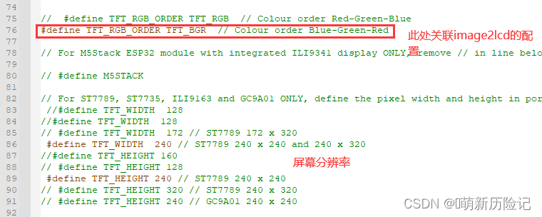
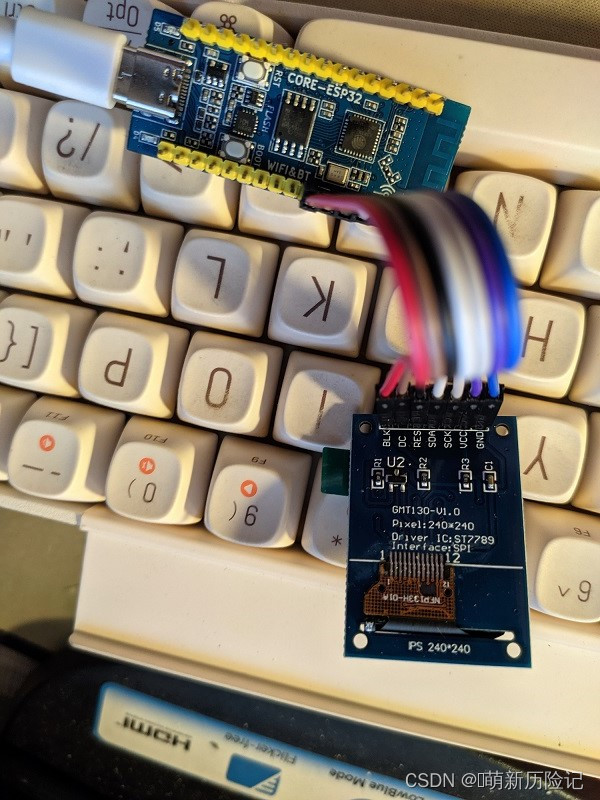
1.3寸LCD ST7789 240*240 屏幕一块(芯澜科技、金逸晨我都买了一块一模一样,屏幕贴膜角颜色是蓝色(这对于配置TFT_eSPI库的配置文件有用),但是可能区别于其他1.3寸,各位注意看清)
其他连接线
2.1连接,物理连接按我另一篇博文0.1.3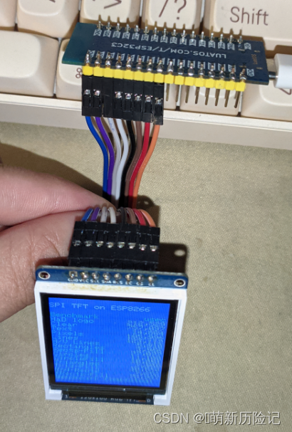
,但那块是ST7735不是ST7789
ST7789配置类似ST7735,这里还是补上7789要改的地方的图吧
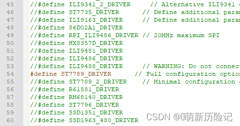
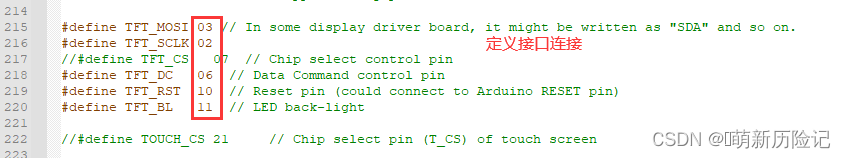
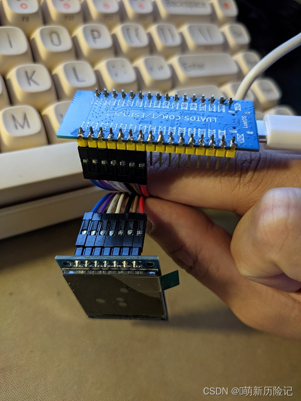
按上面配置,杜邦线不用错位直接直连
3.实现过程
3.1制作图片数组
用image2lcd工具导出*.C/*.H文件
按以下配置设置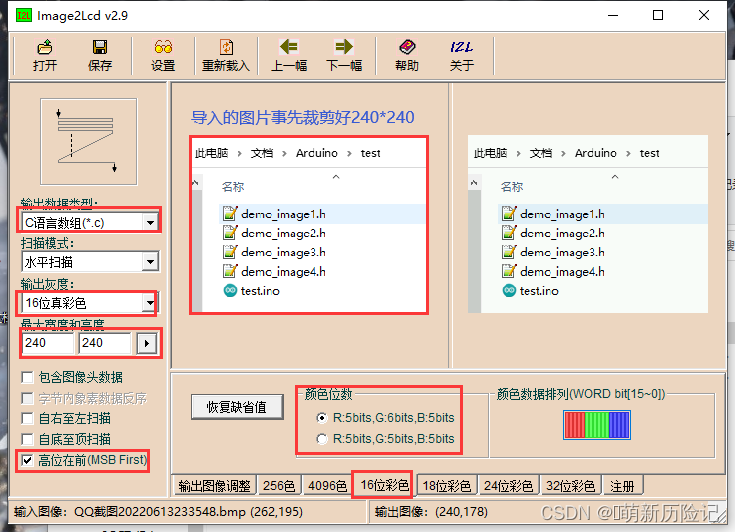
点保存后在 arduino开发文件夹下添加导出的图片数组文件,改名
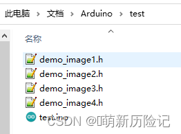
文本编辑器 打开*.h文件,编辑第一行把不带符号的字符串改成不带符号的8位整型
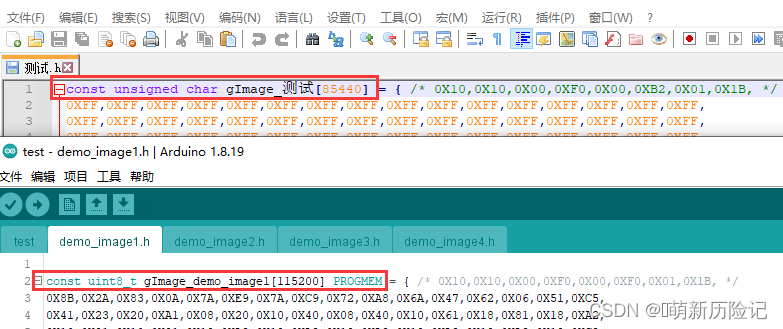
注意改image1的1后续是2、3、4
下面是代码便于复制粘贴
const uint8_t gImage_demo_image1[115200] PROGMEM = 按上面的命名改完,直接复制下面的到主程序同目录下,重新打开arduino编译上传
#include <SPI.h>//声明头文件
#include <TFT_eSPI.h>
#include "demo_image1.h"
#include "demo_image2.h"
#include "demo_image3.h"
#include "demo_image4.h"

TFT_eSPI tft = TFT_eSPI(); //初始化TFT_eSPI对象
#include <JPEGDecoder.h>

// Return the minimum of two values a and b
#define minimum(a,b)     (((a) < (b)) ? (a) : (b))

//####################################################################################################
// Draw a JPEG on the TFT pulled from a program memory array
//####################################################################################################
//void drawArrayJpeg(const uint8_t arrayname[], uint32_t array_size, int xpos, int ypos)
/*{

  int x = xpos;
  int y = ypos;

  JpegDec.decodeArray(arrayname, array_size);

  renderJPEG(x, y);

  Serial.println("#########################");
}
*/
//####################################################################################################
// Draw a JPEG on the TFT, images will be cropped on the right/bottom sides if they do not fit
//####################################################################################################
// This function assumes xpos,ypos is a valid screen coordinate. For convenience images that do not
// fit totally on the screen are cropped to the nearest MCU size and may leave right/bottom borders.
void renderJPEG(int xpos, int ypos)
{

  // retrieve infomration about the image
  uint16_t *pImg;
  uint16_t mcu_w = JpegDec.MCUWidth;
  uint16_t mcu_h = JpegDec.MCUHeight;
  uint32_t max_x = JpegDec.width;
  uint32_t max_y = JpegDec.height;

  // Jpeg images are draw as a set of image block (tiles) called Minimum Coding Units (MCUs)
  // Typically these MCUs are 16x16 pixel blocks
  // Determine the width and height of the right and bottom edge image blocks
  uint32_t min_w = minimum(mcu_w, max_x % mcu_w);
  uint32_t min_h = minimum(mcu_h, max_y % mcu_h);

  // save the current image block size
  uint32_t win_w = mcu_w;
  uint32_t win_h = mcu_h;

  // record the current time so we can measure how long it takes to draw an image
 // uint32_t drawTime = millis();

  // save the coordinate of the right and bottom edges to assist image cropping
  // to the screen size
  max_x += xpos;
  max_y += ypos;

  // read each MCU block until there are no more
  while (JpegDec.readSwappedBytes())
  {
    // save a pointer to the image block
    pImg = JpegDec.pImage ;

    // calculate where the image block should be drawn on the screen
    int mcu_x = JpegDec.MCUx * mcu_w + xpos;  // Calculate coordinates of top left corner of current MCU
    int mcu_y = JpegDec.MCUy * mcu_h + ypos;

    // check if the image block size needs to be changed for the right edge
    if (mcu_x + mcu_w <= max_x) win_w = mcu_w;
    else win_w = min_w;

    // check if the image block size needs to be changed for the bottom edge
    if (mcu_y + mcu_h <= max_y) win_h = mcu_h;
    else win_h = min_h;

    // copy pixels into a contiguous block
    if (win_w != mcu_w)
    {
      uint16_t *cImg;
      int p = 0;
      cImg = pImg + win_w;
      for (int h = 1; h < win_h; h++)
      {
        p += mcu_w;
        for (int w = 0; w < win_w; w++)
        {
          *cImg = *(pImg + w + p);
          cImg++;
        }
      }
    }

    // draw image MCU block only if it will fit on the screen
    if (( mcu_x + win_w ) <= tft.width() && ( mcu_y + win_h ) <= tft.height())
    {
      tft.pushRect(mcu_x, mcu_y, win_w, win_h, pImg);
    }
    else if ( (mcu_y + win_h) >= tft.height()) JpegDec.abort(); // Image has run off bottom of screen so abort decoding
  }
}


void setup() //屏幕初始化
{
  Serial.begin(115200);
  tft.begin();
  tft.setRotation(0);
  tft.fillScreen(TFT_GREEN);//初始化屏幕颜色大写
}

void loop()//展示图片和时间间隔
{

  tft.pushImage(0, 0, 240, 240, (uint16_t*)gImage_demo_image1);
  delay(1000);
  tft.pushImage(0, 0, 240, 240, (uint16_t*)gImage_demo_image2);
  delay(1000);
  tft.pushImage(0, 0, 240, 240, (uint16_t*)gImage_demo_image3);
  delay(1000);
  tft.pushImage(0, 0, 240, 240, (uint16_t*)gImage_demo_image4);
  delay(1000);

}
效果图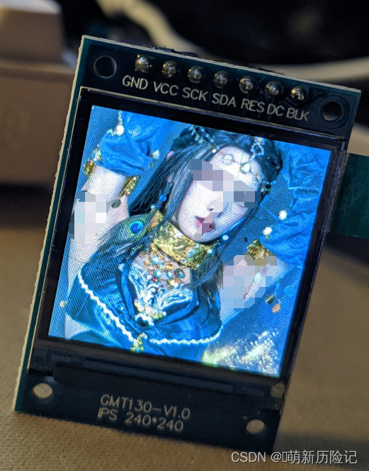
图片来源 永劫无间 官网,此处仅做效果图,没有版权所有,所以我给他打码了
以上代码是简化过的,所有//后的都可以删掉,代码共四部分 第一部分声明库和文件头,第二部分处理图像数组进行绘制图像,第三部分初始化屏幕,第四部分输出循环,简化的原因,原参考的博文源代码有一丢丢小问题,编译不通过,还有就是那个是通配几种开发板,新手不友好
老规矩 上源原文,详细但不太新手友好,想深入研究的可以好好钻研下完整的Arduino应用开发——LCD显示图片_柒壹漆的博客-CSDN博客_arduino显示屏显示图片LCD是项目中比较常用的外设,基于Arduino开发有个好处就是它很多相关的库可用,这对于项目的开发或者前期的方案验证来说是非常方便的,缺点是灵活性较差。Arduino支持很多硬件,我们这一讲主要基于ESP8266和ESP32来讲解图片的显示。https://blog.csdn.net/ShenZhen_zixian/article/details/122682500
最后感谢这位老哥的例程,虽然有小错误但是帮我知道怎么让LCD显示图了
自学需要持之以恒,加油 各位爱好者


 7746
7746


 被折叠的 条评论
为什么被折叠?
被折叠的 条评论
为什么被折叠?
 到【灌水乐园】发言


