


实验拓扑:
实验背景:
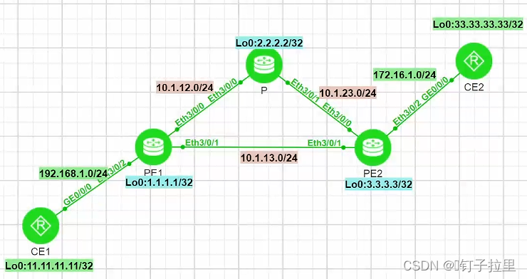
本次实验为SR-MPLS的TE实验流量工程;基于Adjacecy Segment路由转发,灵活控制转发路径。在此拓扑中由于没有做TE,默认会基于IGP转发,CE1与CE2通信时,数据走到PE1,PE1有这两条去往CE2的路径,根据传统的IGP转发,会选择开销最小的一条路径(PE1 -- PE2),而我们通过调整PE1-PE2链路的COST,来使PE1-P-PE2的路由在IGP层面最优;再通过流量工程,控制流量基于Adjacecy Segment转发,手工指定CE1 -- CE2沿途的路径为PE1 -- P -- PE2;
实验思路:
- PE和CE之间建立VPN实例,隔离业务流量;
- 广域网中的设备运行底层IGP协议,确保环回地址可达,使其作为后续BGP的更新源;
- SR域中配置MP-BGP,为业务流量分配内部标签,并且与CE端双向重分发,建立路由表作为控制层面;
- 全局开启MPLS-TE功能,并且在IGP下配置SRGB,为每个SR域中的节点定义Prefix Segment;
- 手工指定Adjacecy Segment,并基于Adjacecy 创建一条显示路径隧道(实现TE的关键);
实验步骤:
一、PE与CE建立邻居;
两个站点的PE和CE之间建立动态路由协议,使其PE能够收取到来自客户端设备的业务路由,并使用VPN实例对其进行隔离;
PE1:
ip vpn-instance SR
 ipv4-family
  route-distinguisher 10:10
  apply-label per-instance
  vpn-target 10:10 export-extcommunity
  vpn-target 10:10 import-extcommunity

ospf 1 router-id 1.1.1.1 vpn-instance SR
 area 0.0.0.0

interface Ethernet3/0/2
 undo shutdown
 ip binding vpn-instance SR
 ip address 192.168.1.254 255.255.255.0
 ospf enable 1 area 0.0.0.0

//创建VPN 实例名称为SR 并将对接CE接口划分到VPN实例下且宣告OSPF进程;
CE1:
ospf 1 router-id 11.11.11.11
 area 0.0.0.0

interface GE0/0/0
 ip address 192.168.1.1 255.255.255.0
 ospf enable 1 area 0.0.0.0

interface LoopBack0
 ip address 11.11.11.11 255.255.255.255
 ospf enable 1 area 0.0.0.0
PE2:
ip vpn-instance SR
 ipv4-family
  route-distinguisher 10:10
  apply-label per-instance
  vpn-target 10:10 export-extcommunity
  vpn-target 10:10 import-extcommunity

ospf 1 router-id 3.3.3.3 vpn-instance SR
 area 0.0.0.0

interface Ethernet3/0/2
 undo shutdown
 ip binding vpn-instance SR
 ip address 172.16.1.254 255.255.255.0
 ospf enable 1 area 0.0.0.0

//创建VPN 实例名称为SR 并将对接CE接口划分到VPN实例下且宣告OSPF进程;
CE1:
ospf 1 router-id 33.33.33.33
 area 0.0.0.0

interface GE0/0/0
 ip address 172.16.1.1 255.255.255.0
 ospf enable 1 area 0.0.0.0

interface LoopBack0
 ip address 33.33.33.33 255.255.255.255
 ospf enable 1 area 0.0.0.0
验证:
在PE上验证下与客户端设备业务流量的连通性
[PE1]ping -vpn-instance SR 11.11.11.11
  PING 11.11.11.11: 56  data bytes, press CTRL_C to break
    Reply from 11.11.11.11: bytes=56 Sequence=1 ttl=255 time=12 ms
    Reply from 11.11.11.11: bytes=56 Sequence=2 ttl=255 time=13 ms
    Reply from 11.11.11.11: bytes=56 Sequence=3 ttl=255 time=18 ms
    Reply from 11.11.11.11: bytes=56 Sequence=4 ttl=255 time=17 ms
    Reply from 11.11.11.11: bytes=56 Sequence=5 ttl=255 time=17 ms

  --- 11.11.11.11 ping statistics ---
    5 packet(s) transmitted
    5 packet(s) received
    0.00% packet loss
    round-trip min/avg/max = 12/15/18 ms


[PE2]ping -vpn-instance SR 33.33.33.33
  PING 33.33.33.33: 56  data bytes, press CTRL_C to break
    Reply from 33.33.33.33: bytes=56 Sequence=1 ttl=255 time=19 ms
    Reply from 33.33.33.33: bytes=56 Sequence=2 ttl=255 time=31 ms
    Reply from 33.33.33.33: bytes=56 Sequence=3 ttl=255 time=20 ms
    Reply from 33.33.33.33: bytes=56 Sequence=4 ttl=255 time=30 ms
    Reply from 33.33.33.33: bytes=56 Sequence=5 ttl=255 time=15 ms

  --- 33.33.33.33 ping statistics ---
    5 packet(s) transmitted
    5 packet(s) received
    0.00% packet loss
    round-trip min/avg/max = 15/23/31 ms
二、SR域中建立IGP协议;
PE1、P、PE2三台设备建立IGP,并将Loopback接口宣告进IGP进程中,使其SR域中的三台设备环回口可达,用于后续作为BGP的更新源地址,以及显示路径隧道的原地址;
PE1:
isis 1
 is-level level-2
 cost-style wide
 network-entity 49.0001.0010.0000.0001.00
 is-name PE1

interface Ethernet3/0/0
 undo shutdown
 ip address 10.1.12.1 255.255.255.0
 isis enable 1

interface Ethernet3/0/1
 undo shutdown
 ip address 10.1.13.1 255.255.255.0
 isis enable 1

interface LoopBack0
 ip address 1.1.1.1 255.255.255.255
 isis enable 1
P:
isis 1
 is-level level-2
 cost-style wide
 network-entity 49.0001.0020.0000.0002.00
 is-name P

interface Ethernet3/0/0
 undo shutdown
 ip address 10.1.12.2 255.255.255.0
 isis enable 1

interface Ethernet3/0/1
 undo shutdown
 ip address 10.1.23.2 255.255.255.0
 isis enable 1

interface LoopBack0
 ip address 2.2.2.2 255.255.255.255
 isis enable 1
PE2:
isis 1
 is-level level-2
 cost-style wide
 network-entity 49.0001.0030.0000.0003.00
 is-name PE2

interface Ethernet3/0/0
 undo shutdown
 ip address 10.1.23.3 255.255.255.0
 isis enable 1

interface Ethernet3/0/1
 undo shutdown
 ip address 10.1.13.3 255.255.255.0
 isis enable 1


interface LoopBack0
 ip address 3.3.3.3 255.255.255.255
 isis enable 1
验证:
PE1与PE2测试环回口可达性:
[PE1]ping -a 1.1.1.1 3.3.3.3
  PING 3.3.3.3: 56  data bytes, press CTRL_C to break
    Reply from 3.3.3.3: bytes=56 Sequence=1 ttl=255 time=54 ms
    Reply from 3.3.3.3: bytes=56 Sequence=2 ttl=255 time=11 ms
    Reply from 3.3.3.3: bytes=56 Sequence=3 ttl=255 time=16 ms
    Reply from 3.3.3.3: bytes=56 Sequence=4 ttl=255 time=31 ms

  --- 3.3.3.3 ping statistics ---
    4 packet(s) transmitted
    4 packet(s) received
    0.00% packet loss
    round-trip min/avg/max = 11/28/54 ms
三、SR域中配置MP-BGP,并且与CE双向重分发;
PE1、P、PE2三台设备配置MP-BGP,为业务流量分配内部标签,并且与CE端双向重分发,建立路由表作为控制层面;
PE1:
bgp 65000
 undo default ipv4-unicast
 private-4-byte-as enable
 peer 2.2.2.2 as-number 65000
 peer 2.2.2.2 connect-interface LoopBack0
 #
 ipv4-family unicast
  undo synchronization
  peer 2.2.2.2 enable
 #
 ipv4-family vpnv4
  policy vpn-target
  peer 2.2.2.2 enable
 #
 ipv4-family vpn-instance SR
  import-route ospf 1                //引入ospf的路由

ospf 1 router-id 1.1.1.1 vpn-instance SR
 import-route bgp                    //引入bgp的路由
 area 0.0.0.0
P:
bgp 65000
 undo default ipv4-unicast
 private-4-byte-as enable
 peer 1.1.1.1 as-number 65000
 peer 1.1.1.1 connect-interface LoopBack0
 peer 3.3.3.3 as-number 65000
 peer 3.3.3.3 connect-interface LoopBack0
 #
 ipv4-family unicast
  undo synchronization
  peer 1.1.1.1 enable
  peer 3.3.3.3 enable
 #
 ipv4-family vpnv4
  undo policy vpn-target
  peer 1.1.1.1 enable
  peer 1.1.1.1 reflect-client
  peer 3.3.3.3 enable
  peer 3.3.3.3 reflect-client
PE2:
bgp 65000
 undo default ipv4-unicast
 private-4-byte-as enable
 peer 2.2.2.2 as-number 65000
 peer 2.2.2.2 connect-interface LoopBack0
 #
 ipv4-family unicast
  undo synchronization
  peer 2.2.2.2 enable
 #
 ipv4-family vpnv4
  policy vpn-target
  peer 2.2.2.2 enable
 #
 ipv4-family vpn-instance SR
  import-route ospf 1           //引入ospf路由
#

ospf 1 router-id 3.3.3.3 vpn-instance SR
 import-route bgp               //引入BGP路由
 area 0.0.0.0
验证:
在PE上Ping测试CE的业务路由;
[PE1]ping -vpn-instance SR 11.11.11.11
  PING 11.11.11.11: 56  data bytes, press CTRL_C to break
    Reply from 11.11.11.11: bytes=56 Sequence=1 ttl=255 time=19 ms
    Reply from 11.11.11.11: bytes=56 Sequence=2 ttl=255 time=18 ms
    Reply from 11.11.11.11: bytes=56 Sequence=3 ttl=255 time=18 ms
    Reply from 11.11.11.11: bytes=56 Sequence=4 ttl=255 time=19 ms
    Reply from 11.11.11.11: bytes=56 Sequence=5 ttl=255 time=16 ms

  --- 11.11.11.11 ping statistics ---
    5 packet(s) transmitted
    5 packet(s) received
    0.00% packet loss
    round-trip min/avg/max = 16/18/19 ms


[PE2]ping -vpn-instance SR 33.33.33.33
  PING 33.33.33.33: 56  data bytes, press CTRL_C to break
    Reply from 33.33.33.33: bytes=56 Sequence=1 ttl=255 time=63 ms
    Reply from 33.33.33.33: bytes=56 Sequence=2 ttl=255 time=34 ms
    Reply from 33.33.33.33: bytes=56 Sequence=3 ttl=255 time=33 ms
    Reply from 33.33.33.33: bytes=56 Sequence=4 ttl=255 time=38 ms
    Reply from 33.33.33.33: bytes=56 Sequence=5 ttl=255 time=73 ms

  --- 33.33.33.33 ping statistics ---
    5 packet(s) transmitted
    5 packet(s) received
    0.00% packet loss
    round-trip min/avg/max = 33/48/73 ms
四、配置SR部分:
(1)广域网设备使能全局SR并在全局下开启流量工程,并指定MPLS的更新源
PE1:
mpls lsr-id 1.1.1.1
#
mpls
 mpls te
P:
mpls lsr-id 2.2.2.2
#
mpls
 mpls te
PE2:
mpls lsr-id 3.3.3.3
#
mpls
 mpls te
(2)在ISIS进程使能SR并且规划SRGB
为SR域内的所有设备定义Prefix范围:
isis 1
 segment-routing mpls
 segment-routing global-block 16000 17000
(3)为SR域中每个节点定义Prefix Segment ID
PE1:
interface LoopBack0
 isis prefix-sid index 1
P:
interface LoopBack0
 isis prefix-sid index 2
PE2:
interface LoopBack0
 isis prefix-sid index 3
简单验证:
[PE2]dis segment-routing prefix mpls forwarding

                   Segment Routing Prefix MPLS Forwarding Information
             --------------------------------------------------------------
             Role : I-Ingress, T-Transit, E-Egress, I&T-Ingress And Transit

Prefix             Label      OutLabel   Interface         NextHop          Role  MPLSMtu   Mtu     State
-----------------------------------------------------------------------------------------------------------------
1.1.1.1/32         16001      16001      Eth3/0/0          10.1.23.2        I&T   ---       1500    Active
2.2.2.2/32         16002      3          Eth3/0/0          10.1.23.2        I&T   ---       1500    Active
3.3.3.3/32         16003      NULL       Loop0             127.0.0.1        E     ---       1500    Active
至此现在CE之间是可达的,通过IGP指导转发的,由于路径PE1-PE2开销优于PE1-P-PE2,所以路径应该是走下面的;
[CE1]tracert -a  11.11.11.11 33.33.33.33
 traceroute to 33.33.33.33(33.33.33.33), max hops: 64, packet length: 40, press CTRL_C to break
 1 192.168.1.254 29 ms  13 ms  14 ms
 2 172.16.1.254 86 ms  52 ms  34 ms
 3 33.33.33.33 85 ms  75 ms  62 ms

//路由跟踪发现PE1直接将流量转发至PE2;
我们修改PE1和PE2之间的开销值;
PE1&PE2
interface Ethernet3/0/1
 isis cost 100
再次进行路由跟踪:
[CE1]tracert -a  11.11.11.11 33.33.33.33
 traceroute to 33.33.33.33(33.33.33.33), max hops: 64, packet length: 40, press CTRL_C to break
 1 192.168.1.254 30 ms  26 ms  32 ms
 2 10.1.12.2 101 ms  63 ms  105 ms
 3 172.16.1.254 85 ms  59 ms  62 ms
 4 33.33.33.33 191 ms  117 ms  102 ms

//由于修改了路径开销,使得路径走了 PE1-P-PE2
接下来我们通过TE 流量工程将路径恢复过来,让路径听我们的,不听IGP的,我们说的做的算(*^▽^*)
(4)定义SR域中的Adjacency Segment,并且基于ADjacency Segment创建显示路径
为PE1与PE2的邻接端定义Adjacency Segment,并创建显示路经(LSP)
PE1:
segment-routing
 ipv4 adjacency local-ip-addr 10.1.13.1 remote-ip-addr 10.1.13.3 sid 323113

//声明本端IP、对端IP、以及Adjacency Segment

explicit-path PE1-PE2            //创建一条显示路径名称为PE1-PE2
 next sid label 323113 type adjacency index 1       //为这条显示路径声明标签(本端的)
PE2:
segment-routing
 ipv4 adjacency local-ip-addr 10.1.13.3 remote-ip-addr 10.1.13.1 sid 323131

//声明本端IP、对端IP、以及Adjacency Segment

explicit-path PE2-PE1            //创建一条显示路径名称为PE1-PE2
 next sid label 323131 type adjacency index 1       //为这条显示路径声明标签(本端的)
验证一哈:
[PE1]dis explicit-path
--------------------------------------------------------------------------------
Path Name :    PE1-PE2     Path Status :  Enabled
 1           323113            Adjacency  Sid-Label
--------------------------------------------------------------------------------
Path Name :    SR     Path Status :  Enabled


[PE2]dis explicit-path
--------------------------------------------------------------------------------
Path Name :    PE2-PE1     Path Status :  Enabled
 1           323131            Adjacency  Sid-Label
(5)创建显示路径的隧道
创建一条隧道,在隧道调用显示标签路径,通过隧道转发;
PE1:
interface Tunnel13
 ip address unnumbered interface LoopBack0      //地址复用 隧道口地址借用环回口地址,节省IP,环回口正好作为Tunnel Source
 tunnel-protocol mpls te                        //隧道协议为SR
 destination 3.3.3.3
 mpls te signal-protocol segment-routing        //信令协议选择为SR
 mpls te tunnel-id 13
 mpls te path explicit-path PE1-PE2             //调用显示路由
PE2:
interface Tunnel13
 ip address unnumbered interface LoopBack0      //地址复用 隧道口地址借用环回口地址,节省IP,环回口正好作为Tunnel Source
 tunnel-protocol mpls te                        //隧道协议为SR
 destination 1.1.1.1
 mpls te signal-protocol segment-routing        //信令协议选择为SR
 mpls te tunnel-id 13
 mpls te path explicit-path PE2-PE1             //调用显示路由
验证一哈
我们可以发现有一条Type为Static-V4的Adjacency,而且他的Label就是我们刚才静态指定的;
[PE1]dis segment-routing adjacency mpls forwarding

            Segment Routing Adjacency MPLS Forwarding Information

Label     Interface          NextHop         Type        MPLSMtu   Mtu       VPN-Name
-------------------------------------------------------------------------------------------------------------
48001     Eth3/0/0           10.1.12.2       ISIS-V4     ---       1500      _public_
48002     Eth3/0/1           10.1.13.3       ISIS-V4     ---       1500      _public_
323113    Eth3/0/1           10.1.13.3       STATIC-V4   ---       1500      _public_

Total information(s): 3
五、配置隧道策略并调用在VPN实例下,使其SR TE由于SR BE;
配置隧道策略后,调用在vpn实例下,当客户流量到达PE之后进行数据转发,会优先选择SR TE隧道;
Tunnul-Policy保证了TE(手工指定)隧道的优先级高于BE(IGP算路);
两台PE的配置:
tunnel-policy SR
 tunnel select-seq sr-te load-balance-number 1

ip vpn-instance SR
 tnl-policy SR
验证一哈:
在路由表中去往CE2路由的下一跳为Tunnel 13
[PE1]dis ip routing-table vpn-instance SR protocol bgp
Route Flags: R - relay, D - download to fib, T - to vpn-instance, B - black hole route
------------------------------------------------------------------------------
SR Routing Table : BGP
         Destinations : 2        Routes : 2

BGP routing table status : <Active>
         Destinations : 2        Routes : 2

Destination/Mask    Proto   Pre  Cost        Flags NextHop                                  Interface

    33.33.33.33/32  IBGP    255  2             RD  3.3.3.3                                  Tunnel13
     172.16.1.0/24  IBGP    255  2             RD  3.3.3.3                                  Tunnel13

BGP routing table status : <Inactive>
         Destinations : 0        Routes : 0
流量工程的现象验证:
此时的环境为:
CE1访问CE2,由于我们修改了PE1-PE2的Cost值,根据IGP算路,路径,为 PE1-P-PE2;
但我们做了流量工程TE在PE1和PE2之间指定了一条显示路径;现在流量的走向应该是PE1-PE2
[CE1]tracert -a 11.11.11.11 33.33.33.33
 traceroute to 33.33.33.33(33.33.33.33), max hops: 64, packet length: 40, press CTRL_C to break
 1 192.168.1.254 43 ms  46 ms  25 ms
 2 172.16.1.254 104 ms  24 ms  48 ms
 3 33.33.33.33 166 ms  132 ms  123 ms
!终于,这次流量的转发没有被IGP所干预,业务流量的数据转发层面没有被限制在IGP固有的SPF算法中,而是选择了我们为其规划、描绘的路径,我们成功使用Traffic Engine为业务流量完成了救赎,摆脱其遭受残酷的最短路径优先算法,而看到这里的你,你也是共同拯救业务流量的天使⁽⁽ଘ( ˊᵕˋ )ଓ⁾⁾*


 2216
2216

 被折叠的 条评论
为什么被折叠?
被折叠的 条评论
为什么被折叠?
 到【灌水乐园】发言


