


MFC 实现图像增强–分段式变换
本文使用visual Studio MFC 平台实现图像增强中的第三大类分段式变换中的三种方法,包括Gray-level slicing,Bit-plane slicing,对比度拉伸.
关于其他MFC单文档工程可参考
01-Visual Studio 使用MFC 单文档工程绘制单一颜色直线和绘制渐变颜色的直线02-visual Studio MFC 绘制单一颜色三角形、渐变颜色边框三角形、渐变填充三角形、边框渐变的正方形与填充渐变的正方形实例
03-visual Studio MFC 平台实现对灰度图添加椒盐噪声,并进行均值滤波与中值滤波
文章目录
一、 Gray-level slicing 灰度级别切片
1.1 灰度级别切片的原理
灰度级别切片(Gray-level Slicing)是一种图像处理技术,其目标是增强或突出显示特定灰度范围内的像素值。这通常用于突出感兴趣的目标或特定区域,并抑制其他区域的细节。
以下是灰度级别切片的基本原理:
-
选择灰度范围: 定义一个或多个灰度范围,这些范围内的像素将被保留或增强,而其他像素将被抑制。
-
设置增强值: 对于选择的灰度范围内的像素,可以将它们的灰度值增强为更高的亮度值,以使其在最终图像中更为突出。
-
抑制其他灰度范围: 对于未选择的灰度范围,可以将它们的灰度值设置为较低的亮度值,从而降低它们在最终图像中的显著性。
-
生成增强后的图像: 根据上述操作生成最终的图像,其中特定灰度范围内的像素得到了增强,而其他像素则被抑制。
这种方法的应用场景包括:
-
目标突出显示: 当你想突出显示图像中的某个特定区域或目标时,可以使用灰度级别切片来使该区域更为显著。
-
降低背景噪声: 如果图像中存在噪声或其他不相关的信息,可以通过灰度级别切片来降低这些不相关信息的影响。
1.2 灰度级别切片的代码实现
void CMFCApplication1View::OnGrayLevelSlicing()
{
    if (gray_data != nullptr) {
        unsigned char* enhanced_data = new unsigned char[bmpWidth * bmpHeight];
        int lower_threshold = 100;  // 定义下限阈值
        int upper_threshold = 200;  // 定义上限阈值

        for (int i = 0; i < bmpWidth * bmpHeight; ++i) {
            if (gray_data[i] >= lower_threshold && gray_data[i] <= upper_threshold) {
                // 在选择的灰度范围内增强像素值
                enhanced_data[i] = 255;
            } else {
                // 在其他范围内抑制像素值
                enhanced_data[i] = 0;
            }
        }

        // 获取绘图设备
        CClientDC dc(this);
        CDC* pDC = &dc;

        // 绘制增强后的灰度图
        m_pBmp->drawGrayBmp(pDC, enhanced_data, bmpWidth, bmpHeight, offset_left + 1100, offset_top);

        // 在图片下方添加文字
        GdiplusStartupInput gdiplusStartupInput;
        ULONG_PTR gdiplusToken;
        GdiplusStartup(&gdiplusToken, &gdiplusStartupInput, nullptr);
        {
            Graphics graphics(pDC->m_hDC);
            Gdiplus::Font font(L"Arial", 12);
            SolidBrush brush(Color(255, 128, 0, 128));  // 文字颜色为紫色

            // 文字的位置
            PointF point(offset_left + 1100, offset_top + bmpHeight + 10);

            // 绘制文字
            graphics.DrawString(L"灰度级别切片", -1, &font, point, &brush);
        }
        GdiplusShutdown(gdiplusToken);

        // 释放内存
        delete[] enhanced_data;
    } else {
        // 处理图像未加载的情况
        AfxMessageBox(_T("未加载图片"));
    }
}
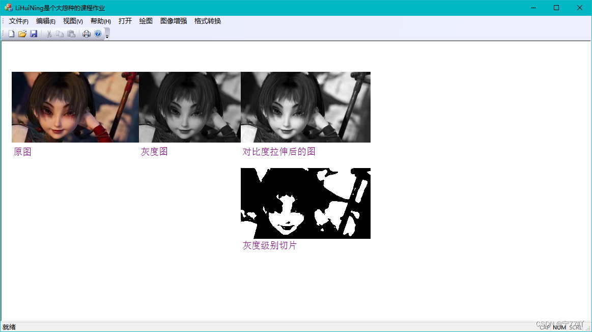
上述代码将在图像中选择一个灰度范围进行增强,并在最终图像中突出显示该范围。
1.3 实现效果
二、 Bit-plane slicing
2.1 Bit-plane slicing 原理
Bit-plane slicing 是一种图像处理技术,它将图像的每个像素的二进制表示按位切割,然后将每个位平面(bit plane)单独显示。这种技术可以用于分析和可视化图像的信息,从而更好地理解图像的结构和特征。
以下是 Bit-plane slicing 的基本原理:
-
二进制表示: 对于每个像素,将其灰度值转换为二进制表示。例如,8 位灰度图像的像素值在二进制中有 8 位。
-
按位切割: 对每个像素的二进制表示,将其按位进行切割。例如,一个像素的 8 位二进制表示可以分为 8 个位平面,每个平面代表一个二进制位。
-
单独显示: 将切割得到的每个位平面单独显示。这意味着显示第一位平面、第二位平面,以此类推。
-
可视化: 通过观察每个位平面的图像,可以更好地理解图像的结构和像素之间的关系。低位平面通常包含图像的全局信息,而高位平面包含更多的细节信息。
-
合成: 可以选择将其中一些位平面重新合成为新的图像,以突出显示某些特定特征或信息。
Bit-plane slicing 主要用于图像分析、图像压缩和图像增强。在分析中,它可以帮助识别图像中的模式和结构。在压缩中,某些位平面可以舍弃以减小图像的大小。在增强中,选择特定位平面可以突出显示某些特征。
2.2 Bit-plane slicing代码实现
void CMFCApplication1View::OnBitplaneSlicing()
{
    if (gray_data != nullptr) {
        // 获取绘图设备
        CClientDC dc(this);
        CDC* pDC = &dc;

        // 选择要显示的位平面,这里选择第 3 位平面(从右往左数)
        int bit_plane = 3;

        // 创建临时数组用于存储位平面数据
        unsigned char* bit_plane_data = new unsigned char[bmpWidth * bmpHeight];

        // 提取位平面数据
        for (int i = 0; i < bmpWidth * bmpHeight; ++i) {
            bit_plane_data[i] = (gray_data[i] >> bit_plane) & 1;
        }

        // 缩放位平面数据以便显示
        int scale_factor = 255;
        for (int i = 0; i < bmpWidth * bmpHeight; ++i) {
            bit_plane_data[i] *= scale_factor;
        }

        // 绘制位平面图像
        m_pBmp->drawGrayBmp(pDC, bit_plane_data, bmpWidth, bmpHeight, offset_left + 1300, offset_top);

        // 在图片下方添加文字
        GdiplusStartupInput gdiplusStartupInput;
        ULONG_PTR gdiplusToken;
        GdiplusStartup(&gdiplusToken, &gdiplusStartupInput, nullptr);
        {
            Graphics graphics(pDC->m_hDC);
            Gdiplus::Font font(L"Arial", 12);
            SolidBrush brush(Color(255, 128, 0, 128));  // 文字颜色为紫色

            // 文字的位置
            PointF point(offset_left + 1300, offset_top + bmpHeight + 10);

            // 绘制文字
            CString text;
            text.Format(L"Bit-plane Slicing (Bit %d)", bit_plane);
            graphics.DrawString(text, -1, &font, point, &brush);
        }
        GdiplusShutdown(gdiplusToken);

        // 释放内存
        delete[] bit_plane_data;
    } else {
        // 处理图像未加载的情况
        AfxMessageBox(_T("未加载图片"));
    }
}
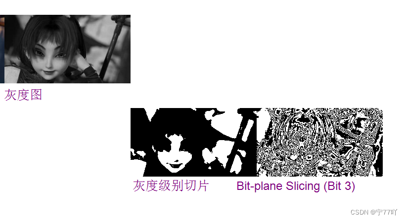
上述代码演示了如何选择特定位平面进行切割并显示。在示例中,选择了第 3 位平面,并在图像下方显示了相应的文字。请注意,位平面的选择从右向左进行,从 0 开始。
2.3 实现效果
三、 对比度拉伸
3.1 对比度拉伸的原理
图像的对比度拉伸是一种调整图像对比度的方法,其原理涉及到像素值的映射。对比度表示图像中不同亮度级别之间的差异程度。拉伸对比度的目的是增强图像中的亮度差异,使图像中的细节更加明显。
对比度拉伸的一般原理如下:
-
找到图像的最小和最大像素值: 遍历整个图像,找到最小和最大的像素值。
-
定义拉伸函数: 根据找到的最小和最大像素值,定义一个拉伸函数,将原始像素值映射到一个新的范围内。这个映射通常使用线性函数完成,将原始像素值拉伸到一个更广泛的范围。
公式示例: 新像素值 = ( 原始像素值 − 最小值 最大值 − 最小值 ) × 新范围大小 \text{新像素值} = \left( \frac{\text{原始像素值} - \text{最小值}}{\text{最大值} - \text{最小值}} \right) \times \text{新范围大小} 新像素值=(最大值−最小值原始像素值−最小值)×新范围大小
-
应用拉伸函数: 将拉伸函数应用于整个图像,调整每个像素的值。这样,原始图像中的亮度差异将在新的范围内更为明显。
对比度拉伸常用于增强图像中的细节,特别是在图像中存在大量像素集中在低对比度范围内的情况。拉伸过程不改变图像的相对亮度顺序,只是将亮度范围映射到更广泛的范围,以便更好地显示图像的细节。
3.2 对比度拉伸代码实现
//对比度拉伸代码
void CMFCApplication1View::OnContraststretching()
{

 CClientDC dc(this);
 CDC* pDC = &dc;
 if (gray_data != nullptr) {
  // 寻找图像的最小和最大像素值
  unsigned int minPixelValue = gray_data[0];
  unsigned int maxPixelValue = gray_data[0];
  // 创建临时数组用于对比度拉伸处理
  unsigned char* temp_data = new unsigned char[bmpWidth * bmpHeight];
  for (int i = 0; i < bmpWidth * bmpHeight; ++i) {
   if (gray_data[i] < minPixelValue) {
    minPixelValue = gray_data[i];
   }

   if (gray_data[i] > maxPixelValue) {
    maxPixelValue = gray_data[i];
   }
  }

  // 对比度拉伸的参数
  const int newMinPixelValue = 0;
  const int newMaxPixelValue = 255;

  // 应用对比度拉伸公式到每个像素
  for (int i = 0; i < bmpWidth * bmpHeight; ++i) {
   temp_data[i] = static_cast<unsigned char>(
    (gray_data[i] - minPixelValue) * (newMaxPixelValue - newMinPixelValue) /
    (maxPixelValue - minPixelValue) + newMinPixelValue);
  }

  // 绘制拉伸后的灰度图
  m_pBmp->drawGrayBmp(pDC, temp_data, bmpWidth, bmpHeight, offset_left + 450, offset_top);
  // 释放临时数组内存
  delete[] temp_data;
  // 更新视图,显示修改后的图像
  //Invalidate();
  // 在图片下方添加文字---只为方便查看
  GdiplusStartupInput gdiplusStartupInput;
  ULONG_PTR gdiplusToken;
  GdiplusStartup(&gdiplusToken, &gdiplusStartupInput, nullptr);
  {
  Graphics graphics(pDC->m_hDC);
  Gdiplus::Font font(L"Arial", 12);
  SolidBrush brush(Color(255,128, 0, 128));  // 文字颜色为紫色

  // 文字的位置
  PointF point(offset_left + 450, offset_top + bmpHeight + 10);

  // 绘制文字
  graphics.DrawString(L"对比度拉伸后的图", -1, &font, point, &brush);
  }
  GdiplusShutdown(gdiplusToken);

 }
 else {
  // 处理图像未加载的情况
  AfxMessageBox(_T("未加载图片"));
  return;
 }
}
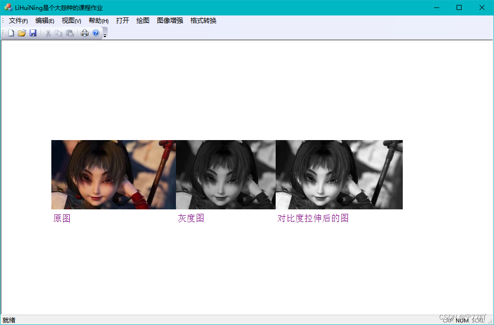
3.3 对比度拉伸的实现图


 7180
7180


 被折叠的 条评论
为什么被折叠?
被折叠的 条评论
为什么被折叠?
 到【灌水乐园】发言


