


要求:
1.IP地址基于192.168.1.0/24划分
2.使用ospf
3全网可达
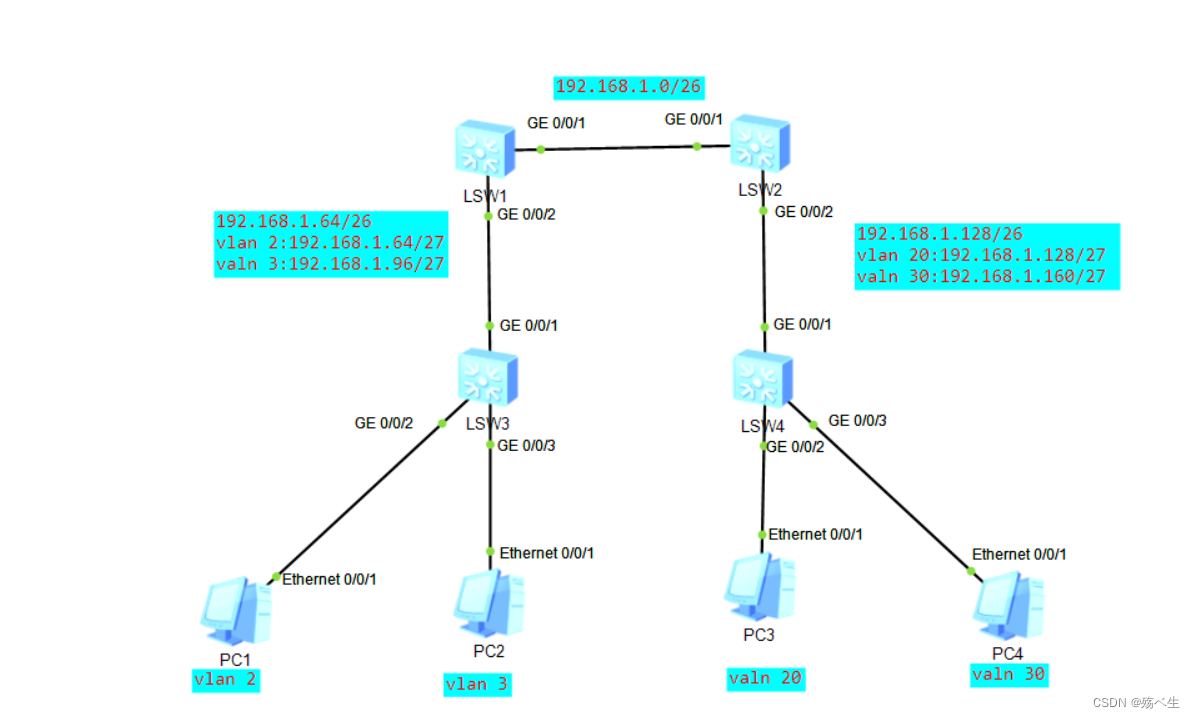
拓扑图
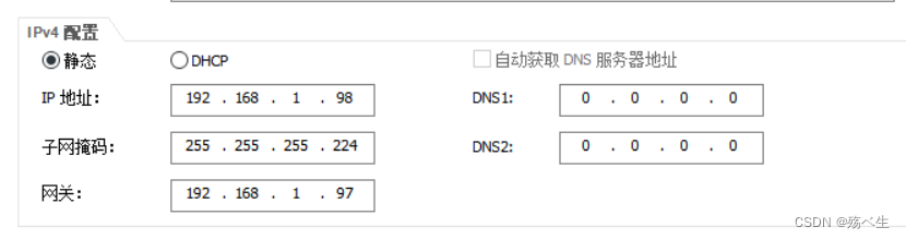
pc1的配置:

pc2的配置:
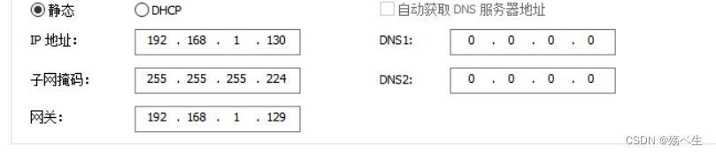
pc3的配置:
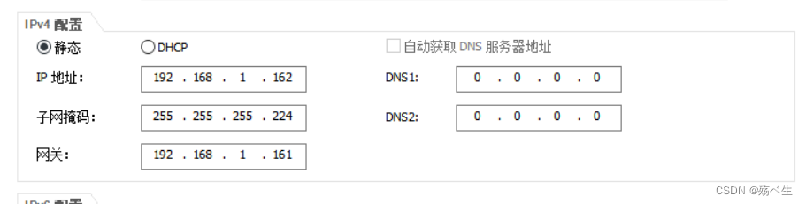
pc4的配置:
指令:
SW1
sysname sw1
vlan batch 2 to 3
interface Vlanif1
ip address 192.168.1.1 255.255.255.192
interface Vlanif2
ip address 192.168.1.65 255.255.255.224
dhcp select global
interface Vlanif3
ip address 192.168.1.97 255.255.255.224
interface GigabitEthernet0/0/2
port link-type trunk
port trunk allow-pass vlan 2 to 3
ospf 1 router-id 1.1.1.1
area 0.0.0.0
network 192.168.1.64 0.0.0.63
network 192.168.1.1 0.0.0.0
SW2
sysname sw2
vlan batch 20 30
interface Vlanif1
ip address 192.168.1.2 255.255.255.192
interface Vlanif20
ip address 192.168.1.129 255.255.255.224
interface Vlanif30
ip address 192.168.1.161 255.255.255.224
interface GigabitEthernet0/0/2
port link-type trunk
port trunk allow-pass vlan 20 30
ospf 1 router-id 2.2.2.2
area 0.0.0.0
network 192.168.1.2 0.0.0.0
area 0.0.0.1
network 192.168.1.128 0.0.0.63
SW3
sysname sw3
vlan batch 2 to 3
interface GigabitEthernet0/0/1
port link-type trunk
port trunk allow-pass vlan 2 to 3
interface GigabitEthernet0/0/2
port link-type access
port default vlan 2
interface GigabitEthernet0/0/3
port link-type access
port default vlan 3
SW4
sysname sw4
vlan batch 20 30
interface GigabitEthernet0/0/1
port link-type trunk
port trunk allow-pass vlan 20 30
interface GigabitEthernet0/0/2
port link-type access
port default vlan 20
interface GigabitEthernet0/0/3
port link-type access
port default vlan 30
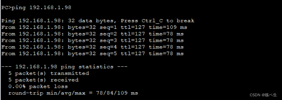
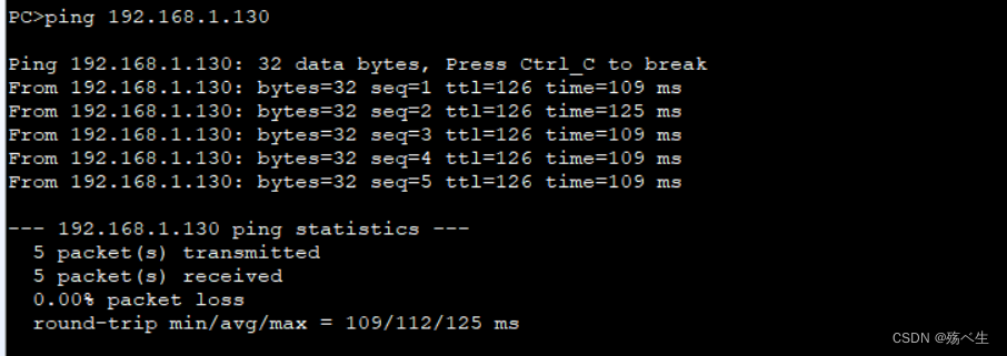
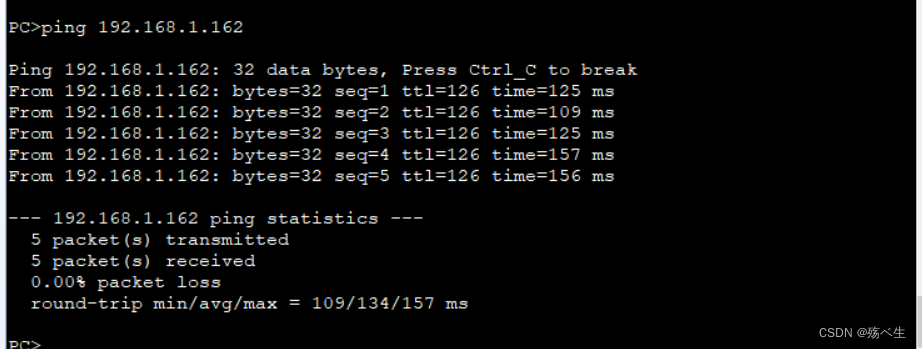
用pc1去ping pc2,pc3,pc4的结果:


 2万+
2万+


 被折叠的 条评论
为什么被折叠?
被折叠的 条评论
为什么被折叠?
 到【灌水乐园】发言


