一、例程简介
本例程51单片机与蓝牙模块连接,可通过蓝牙模块接收和发送字符串,从而控制测试灯的亮灭。其中使用51单片机的串行口2的工作方式1,即8位UART,波特率可变。波特率设为9600。缺省UART2在P1口。
测试程序实现的功能:
1、蓝牙模块接收到“0”~“6”字符串时,分别实现LED0~4的不同亮灭效果;
2、执行字符串“6”对应效果后,通过蓝牙模块发送字符串“\rHello!”到模块连接的蓝牙设备。
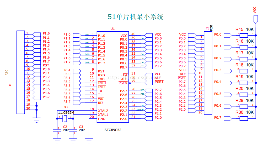
二、硬件部分
C51芯片:STC12C5A60S2 PDIP-40
蓝牙模块:HC-05
晶振:11.0592MHz
-- 连接电路 --
最小系统
(测试用BST-V51 51单片机学习板)
蓝牙模块
+5V 接 单片机VCTC
GND 接 单片机GND
TX 接 P1.2/RxD2
RX 接 P1.3/TxD2
其它引脚悬空
三、软件部分
-- C语言代码 --
#include "reg51.h"
#include "intrins.h"
#include "string.h"
typedef unsigned char uchar;
typedef unsigned int uint;
#define FOSC 11059200L //System frequency
#define BAUD 9600 //UART baudrate
#define PARITYBIT NONE_PARITY //Testing none parity
/*Define UART parity mode*/
/* Copy from STC12C5A60S2 Data Sheet*/
#define NONE_PARITY 0 //None parity
#define ODD_PARITY 1 //Odd parity
#define EVEN_PARITY 2 //Even parity
#define MARK_PARITY 3 //Mark parity
#define SPACE_PARITY 4 //Space parity
/*Declare SFR associated with the UART2 */
/* Copy from STC12C5A60S2 Data Sheet*/
sfr AUXR = 0x8e; //Auxiliary register
sfr AUXR1 = 0xa2;
sfr S2CON = 0x9a; //UART2 control register
sfr S2BUF = 0x9b; //UART2 data buffer
sfr BRT = 0x9c; //Baudrate generator
sfr IE2 = 0xaf; //Interrupt control 2
#define S2RI 0x01 //S2CON.0
#define S2TI 0x02 //S2CON.1
#define S2RB8 0x04 //S2CON.2
#define S2TB8 0x08 //S2CON.3
/* Define variables associated with the UART2*/
char UART_buff;
char Str[16];
uchar j = 0;
/*Define pin of LED for testing*/
sbit LED0 = P1^0;
sbit LED1 = P1^4;
sbit LED2 = P1^5;
sbit LED3 = P1^6;
sbit LED4 = P1^7;
// delay for x ms
void delayxms(uint x)
{
uint i;
uchar a,b;
for(i=0;i<x;i++)
for(b=18;b>0;b--)
for(a=152;a>0;a--) ;
}
/* Copy from STC12C5A60S2 Data Sheet*/
void Uart2_Init()
{
#if (PARITYBIT == NONE_PARITY)
S2CON = 0x50; //8-bit variable UART
#elif (PARITYBIT == ODD_PARITY) || (PARITYBIT == EVEN_PARITY) || (PARITYBIT == MARK_PARITY)
S2CON = 0xda; //9-bit variable UART, parity bit initial to 1
#elif (PARITYBIT == SPACE_PARITY)
S2CON = 0xd5; //9-bit variable UART, parity bit initial to 0
#endif
BRT = -(FOSC/32/BAUD); //Set auto-reload vaule of baudrate generator
AUXR = 0x14; //Baudrate generator work in 1T mode
// AUXR1 |= 0x10; // If needed, switch UART2 Pin from P1 to P4
IE2 = 0x01; //Enable UART2 interrupt
EA = 1; //Open master interrupt switch
}
/*----------------------------
Send a string to UART
Input: s (address of string)
Output:None
----------------------------*/
void SendString(char *s)
{
int i = 0;
int l = strlen(s);
for(i; i<l; i++)
{
S2BUF = s[i];
while(!(S2CON&S2TI)) ;
S2CON &= ~S2TI;;
}
}
void main()
{
Uart2_Init();
LED0 = 1;
LED1 = 1;
LED2 = 1;
LED3 = 1;
LED4 = 1;
while(1) ;
}
/*----------------------------
UART2 interrupt service routine
----------------------------*/
void Uart2() interrupt 8 using 1
{
if (S2CON & S2RI)
{
S2CON &= ~S2RI; //Clear receive interrupt flag
UART_buff = S2BUF; //UART_buff to save UART data
if(UART_buff != '\0') // When it's not the end of message,
{
Str[j++] = UART_buff; // Continue to record character.
}
else // When message ends, do the specific job
{
Str[j] = UART_buff;
if(strcmp(Str, "0") == 0)
{
LED0 = ~LED0;
delayxms(100);
}
else if(strcmp(Str, "1") == 0)
{
LED1 = ~LED1;
delayxms(100);
}
else if(strcmp(Str, "2") == 0)
{
LED2 = ~LED2;
delayxms(100);
}
else if(strcmp(Str, "3") == 0)
{
LED3 = ~LED3;
delayxms(100);
}
else if(strcmp(Str, "4") == 0)
{
LED4 = ~LED4;
delayxms(100);
}
else if(strcmp(Str, "5") == 0)
{
LED1 = 0;
LED2 = 0;
LED3 = 0;
LED4 = 0;
delayxms(100);
}
else if(strcmp(Str, "6") == 0)
{
LED1 = 1;
LED2 = 1;
LED3 = 1;
LED4 = 1;
delayxms(100);
SendString("\rHello!");
}
strcpy(Str, "");
j = 0;
}
}
if (S2CON & S2TI)
{
S2CON &= ~S2TI; //Clear transmit interrupt flag
}
}