


stm32f103使用内部时钟HSI
原代码使用的HSE外部时钟,新版电路去掉了晶振。增加内部HSI时钟初始化。
注意:内部时钟主频只有64M,注意定时器其他器件的时钟变化。
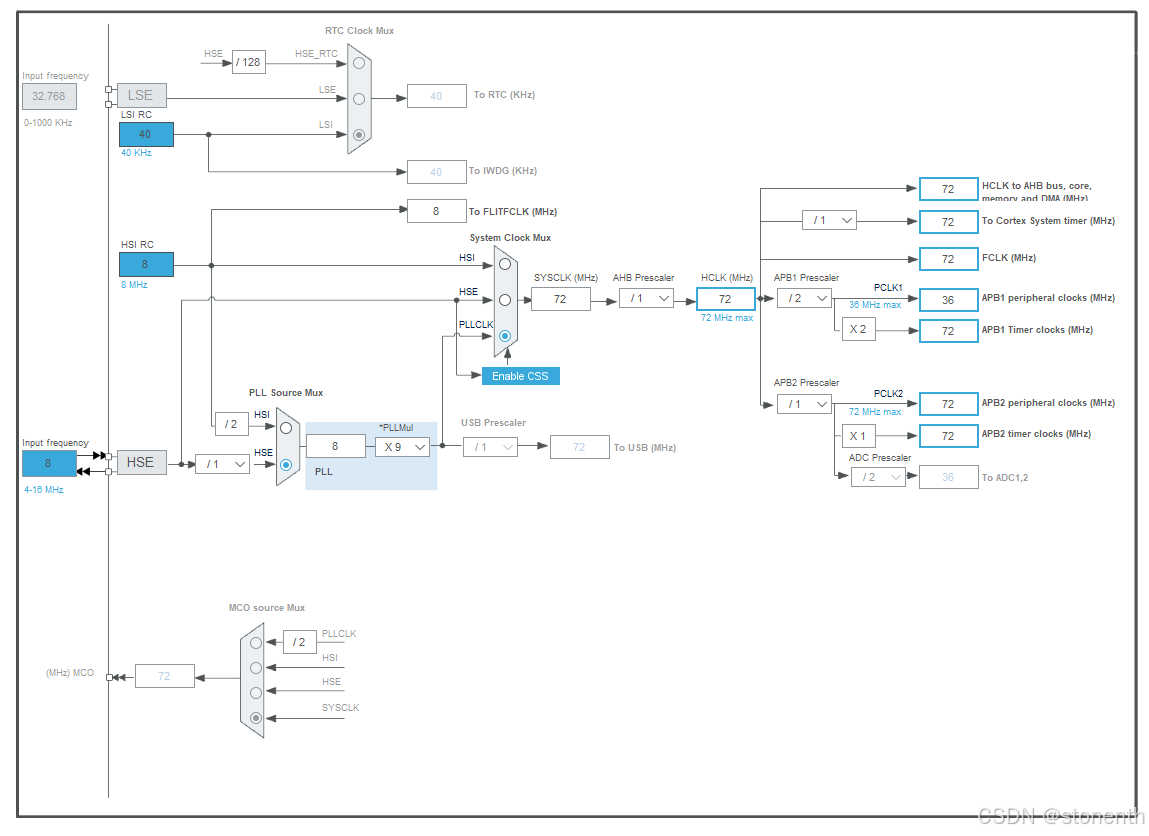
HS时钟设置框图:
首先打开HSE
 HSI时钟设置框图:
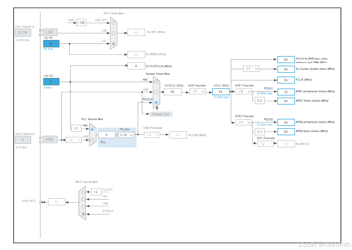
原时钟初HSE始化:
startup_stm32f10x_hd.s文件中:调用SystemInit初始化函数
SystemInit中调用SetSysClock;
SetSysClock调用SetSysClockTo72设置HES初始化。
; Reset handler
Reset_Handler   PROC
                EXPORT  Reset_Handler             [WEAK]
                IMPORT  __main
                IMPORT  SystemInit
                LDR     R0, =SystemInit
                BLX     R0
                LDR     R0, =__main
                BX      R0
                ENDP
/**
  * @brief  Setup the microcontroller system
  *         Initialize the Embedded Flash Interface, the PLL and update the
  *         SystemCoreClock variable.
  * @note   This function should be used only after reset.
  * @param  None
  * @retval None
  */
void SystemInit (void)
{
  /* Reset the RCC clock configuration to the default reset state(for debug purpose) */
  /* Set HSION bit */
  RCC->CR |= (uint32_t)0x00000001;

  /* Reset SW, HPRE, PPRE1, PPRE2, ADCPRE and MCO bits */
#ifndef STM32F10X_CL
  RCC->CFGR &= (uint32_t)0xF8FF0000;
#else
  RCC->CFGR &= (uint32_t)0xF0FF0000;
#endif /* STM32F10X_CL */

  /* Reset HSEON, CSSON and PLLON bits */
  RCC->CR &= (uint32_t)0xFEF6FFFF;

  /* Reset HSEBYP bit */
  RCC->CR &= (uint32_t)0xFFFBFFFF;

  /* Reset PLLSRC, PLLXTPRE, PLLMUL and USBPRE/OTGFSPRE bits */
  RCC->CFGR &= (uint32_t)0xFF80FFFF;

#ifdef STM32F10X_CL
  /* Reset PLL2ON and PLL3ON bits */
  RCC->CR &= (uint32_t)0xEBFFFFFF;

  /* Disable all interrupts and clear pending bits  */
  RCC->CIR = 0x00FF0000;

  /* Reset CFGR2 register */
  RCC->CFGR2 = 0x00000000;
#elif defined (STM32F10X_LD_VL) || defined (STM32F10X_MD_VL) || (defined STM32F10X_HD_VL)
  /* Disable all interrupts and clear pending bits  */
  RCC->CIR = 0x009F0000;

  /* Reset CFGR2 register */
  RCC->CFGR2 = 0x00000000;
#else
  /* Disable all interrupts and clear pending bits  */
  RCC->CIR = 0x009F0000;
#endif /* STM32F10X_CL */

#if defined (STM32F10X_HD) || (defined STM32F10X_XL) || (defined STM32F10X_HD_VL)
  #ifdef DATA_IN_ExtSRAM
    SystemInit_ExtMemCtl();
  #endif /* DATA_IN_ExtSRAM */
#endif

  /* Configure the System clock frequency, HCLK, PCLK2 and PCLK1 prescalers */
  /* Configure the Flash Latency cycles and enable prefetch buffer */
  SetSysClock();

#ifdef VECT_TAB_SRAM
  SCB->VTOR = SRAM_BASE | VECT_TAB_OFFSET; /* Vector Table Relocation in Internal SRAM. */
#else
  SCB->VTOR = FLASH_BASE | VECT_TAB_OFFSET; /* Vector Table Relocation in Internal FLASH. */
#endif
}
/**
  * @brief  Configures the System clock frequency, HCLK, PCLK2 and PCLK1 prescalers.
  * @param  None
  * @retval None
  */
static void SetSysClock(void)
{
#ifdef SYSCLK_FREQ_HSE
  SetSysClockToHSE();
#elif defined SYSCLK_FREQ_24MHz
  SetSysClockTo24();
#elif defined SYSCLK_FREQ_36MHz
  SetSysClockTo36();
#elif defined SYSCLK_FREQ_48MHz
  SetSysClockTo48();
#elif defined SYSCLK_FREQ_56MHz
  SetSysClockTo56();
#elif defined SYSCLK_FREQ_72MHz
  SetSysClockTo72();
#endif

 /* If none of the define above is enabled, the HSI is used as System clock
    source (default after reset) */
}
#elif defined SYSCLK_FREQ_72MHz
/**
  * @brief  Sets System clock frequency to 72MHz and configure HCLK, PCLK2
  *          and PCLK1 prescalers.
  * @note   This function should be used only after reset.
  * @param  None
  * @retval None
  */
static void SetSysClockTo72(void)
{
  __IO uint32_t StartUpCounter = 0, HSEStatus = 0;

  /* SYSCLK, HCLK, PCLK2 and PCLK1 configuration ---------------------------*/
  /* Enable HSE */
  RCC->CR |= ((uint32_t)RCC_CR_HSEON);

  /* Wait till HSE is ready and if Time out is reached exit */
  do
  {
    HSEStatus = RCC->CR & RCC_CR_HSERDY;
    StartUpCounter++;
  } while((HSEStatus == 0) && (StartUpCounter != HSE_STARTUP_TIMEOUT));

  if ((RCC->CR & RCC_CR_HSERDY) != RESET)
  {
    HSEStatus = (uint32_t)0x01;
  }
  else
  {
    HSEStatus = (uint32_t)0x00;
  }

  if (HSEStatus == (uint32_t)0x01)
  {
    /* Enable Prefetch Buffer */
    FLASH->ACR |= FLASH_ACR_PRFTBE;

    /* Flash 2 wait state */
    FLASH->ACR &= (uint32_t)((uint32_t)~FLASH_ACR_LATENCY);
    FLASH->ACR |= (uint32_t)FLASH_ACR_LATENCY_2;


    /* HCLK = SYSCLK */
    RCC->CFGR |= (uint32_t)RCC_CFGR_HPRE_DIV1;

    /* PCLK2 = HCLK */
    RCC->CFGR |= (uint32_t)RCC_CFGR_PPRE2_DIV1;

    /* PCLK1 = HCLK */
    RCC->CFGR |= (uint32_t)RCC_CFGR_PPRE1_DIV2;

#ifdef STM32F10X_CL
    /* Configure PLLs ------------------------------------------------------*/
    /* PLL2 configuration: PLL2CLK = (HSE / 5) * 8 = 40 MHz */
    /* PREDIV1 configuration: PREDIV1CLK = PLL2 / 5 = 8 MHz */

    RCC->CFGR2 &= (uint32_t)~(RCC_CFGR2_PREDIV2 | RCC_CFGR2_PLL2MUL |
                              RCC_CFGR2_PREDIV1 | RCC_CFGR2_PREDIV1SRC);
    RCC->CFGR2 |= (uint32_t)(RCC_CFGR2_PREDIV2_DIV5 | RCC_CFGR2_PLL2MUL8 |
                             RCC_CFGR2_PREDIV1SRC_PLL2 | RCC_CFGR2_PREDIV1_DIV5);

    /* Enable PLL2 */
    RCC->CR |= RCC_CR_PLL2ON;
    /* Wait till PLL2 is ready */
    while((RCC->CR & RCC_CR_PLL2RDY) == 0)
    {
    }


    /* PLL configuration: PLLCLK = PREDIV1 * 9 = 72 MHz */
    RCC->CFGR &= (uint32_t)~(RCC_CFGR_PLLXTPRE | RCC_CFGR_PLLSRC | RCC_CFGR_PLLMULL);
    RCC->CFGR |= (uint32_t)(RCC_CFGR_PLLXTPRE_PREDIV1 | RCC_CFGR_PLLSRC_PREDIV1 |
                            RCC_CFGR_PLLMULL9);
#else
    /*  PLL configuration: PLLCLK = HSE * 9 = 72 MHz */
    RCC->CFGR &= (uint32_t)((uint32_t)~(RCC_CFGR_PLLSRC | RCC_CFGR_PLLXTPRE |
                                        RCC_CFGR_PLLMULL));
    RCC->CFGR |= (uint32_t)(RCC_CFGR_PLLSRC_HSE | RCC_CFGR_PLLMULL9);
#endif /* STM32F10X_CL */

    /* Enable PLL */
    RCC->CR |= RCC_CR_PLLON;

    /* Wait till PLL is ready */
    while((RCC->CR & RCC_CR_PLLRDY) == 0)
    {
    }

    /* Select PLL as system clock source */
    RCC->CFGR &= (uint32_t)((uint32_t)~(RCC_CFGR_SW));
    RCC->CFGR |= (uint32_t)RCC_CFGR_SW_PLL;

    /* Wait till PLL is used as system clock source */
    while ((RCC->CFGR & (uint32_t)RCC_CFGR_SWS) != (uint32_t)0x08)
    {
    }
  }
  else
  { /* If HSE fails to start-up, the application will have wrong clock
         configuration. User can add here some code to deal with this error */
         //可在此处添加HSI时钟初始化,在HSE失败后,使用内部时钟HSI
         //SetSysClockHSI64();


  }
}
#endif
可在上面函数中增加HSE初始化失败的处理,使用内部时钟HSI。
内部时钟初始化函数如下:
void SetSysClockHSI64(void)
{
    RCC_DeInit();//将外设 RCC寄存器重设为缺省值,复位
    RCC_HSICmd(ENABLE);//使能HSI
    while(RCC_GetFlagStatus(RCC_FLAG_HSIRDY) == RESET);      //等待HSI使能成功

    //使能Flash与存储缓冲区,flash设置相关,查看闪存编程手册
    FLASH->ACR |= FLASH_ACR_PRFTBE;
    FLASH->ACR &= (uint32_t)((uint32_t)~FLASH_ACR_LATENCY);  //清除LATENCY位
    FLASH->ACR |= (uint32_t)FLASH_ACR_LATENCY_2;

    RCC_HCLKConfig(RCC_SYSCLK_Div1); //设置AHB的分频系数
    RCC_PCLK1Config(RCC_HCLK_Div2);  //设置APB1的分频系数
    RCC_PCLK2Config(RCC_HCLK_Div1);  //设置APB2的分频系数

    //设置 PLL 时钟源及倍频系数
    RCC_PLLConfig(RCC_PLLSource_HSI_Div2, RCC_PLLMul_16);
    RCC_PLLCmd(ENABLE);//如果PLL被用于系统时钟,那么它不能被失能

    //等待指定的 RCC 标志位设置成功 等待PLL初始化成功
    while(RCC_GetFlagStatus(RCC_FLAG_PLLRDY) == RESET);

    //设置系统时钟(SYSCLK) 设置PLL为系统时钟源
    RCC_SYSCLKConfig(RCC_SYSCLKSource_PLLCLK);//选择想要的系统时钟
    //等待PLL成功用作于系统时钟的时钟源

    //  0x00:HSI 作为系统时钟
    //  0x04:HSE作为系统时钟
    //  0x08:PLL作为系统时钟
    while(RCC_GetSYSCLKSource() != 0x08);//需与被选择的系统时钟对应起来
}


 2305
2305

 被折叠的 条评论
为什么被折叠?
被折叠的 条评论
为什么被折叠?
 到【灌水乐园】发言


