


1.前言
根据bl1\bl1.ld.S可以看出来,入口点是bl1_entrypoint。其主要执行BL1初始化,平台初始化,加载下一阶段镜像,以及跳转到下一阶段执行。
OUTPUT_FORMAT(PLATFORM_LINKER_FORMAT)
OUTPUT_ARCH(PLATFORM_LINKER_ARCH)
ENTRY(bl1_entrypoint)
2.主要代码流程
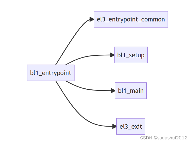
2.1 el3_entrypoint_common
	/* ---------------------------------------------------------------------
	 * If the reset address is programmable then bl1_entrypoint() is
	 * executed only on the cold boot path. Therefore, we can skip the warm
	 * boot mailbox mechanism.
	 * ---------------------------------------------------------------------
	 */
	el3_entrypoint_common					\
		_init_sctlr=1					\
		_warm_boot_mailbox=!PROGRAMMABLE_RESET_ADDRESS	\
		_secondary_cold_boot=!COLD_BOOT_SINGLE_CPU	\
		_init_memory=1					\
		_init_c_runtime=1				\
		_exception_vectors=bl1_exceptions		\
_pie_fixup_size=0el3_entrypoint_common是定义的一个宏,它是EL3等级下执行的入口通用函数,其实现位于el3_common_macros.S,主要完成C语言运行环境的搭建,异常向量表的注册,bl1镜像文件的复制,CPU安全运行环境的设定 。
2.1.1 _init_sctlr
初始化EL3异常等级下的系统控制器,包括设置系统小端,禁止可写内存的执行权限,启用栈对齐检查,对齐错误检查等
.if \_init_sctlr
		/* -------------------------------------------------------------
		 * This is the initialisation of SCTLR_EL3 and so must ensure
		 * that all fields are explicitly set rather than relying on hw.
		 * Some fields reset to an IMPLEMENTATION DEFINED value and
		 * others are architecturally UNKNOWN on reset.
		 *
		 * SCTLR.EE: Set the CPU endianness before doing anything that
		 *  might involve memory reads or writes. Set to zero to select
		 *  Little Endian.
		 *
		 * SCTLR_EL3.WXN: For the EL3 translation regime, this field can
		 *  force all memory regions that are writeable to be treated as
		 *  XN (Execute-never). Set to zero so that this control has no
		 *  effect on memory access permissions.
		 *
		 * SCTLR_EL3.SA: Set to zero to disable Stack Alignment check.
		 *
		 * SCTLR_EL3.A: Set to zero to disable Alignment fault checking.
		 *
		 * SCTLR.DSSBS: Set to zero to disable speculation store bypass
		 *  safe behaviour upon exception entry to EL3.
		 * -------------------------------------------------------------
		 */
		mov_imm	x0, (SCTLR_RESET_VAL & ~(SCTLR_EE_BIT | SCTLR_WXN_BIT \
				| SCTLR_SA_BIT | SCTLR_A_BIT | SCTLR_DSSBS_BIT))
		msr	sctlr_el3, x0
		isb //指令同步屏障
	.endif /* _init_sctlr */
#define SCTLR_EL3_RES1 ((U(1) << 29) | (U(1) << 28) | (U(1) << 23) | \
(U(1) << 22) | (U(1) << 18) | (U(1) << 16) | \
(U(1) << 11) | (U(1) << 5) | (U(1) << 4))2.1.2 _warm_boot_mailbox
.if \_warm_boot_mailbox
		/* -------------------------------------------------------------
		 * This code will be executed for both warm and cold resets.
		 * Now is the time to distinguish between the two.
		 * Query the platform entrypoint address and if it is not zero
		 * then it means it is a warm boot so jump to this address.
		 * -------------------------------------------------------------
		 */
		bl	plat_get_my_entrypoint
		cbz	x0, do_cold_boot
		br	x0

	do_cold_boot:
	.endif /* _warm_boot_mailbox */
冷启动和热启动的最大区别就是冷启动需要执行完整的系统初始化流程,而热启动因为在启动前保存了相关状态,因此可以跳过这些阶段,从而加快启动速度。因此,这段代码就很好理解了,它先通过plat_get_my_entrypoint从特定平台获取热启动地址,若地址获取成功,则直接跳转到该地址执行热启动流程。若地址获取失败,该函数会返回0,此时表明本次启动是冷启动,因此急需执行冷启动流程.
以marvell为实例,代码路径:plat\marvell\armada\a8k\common\aarch64\plat_helpers.S
func plat_get_my_entrypoint
	/* Read first word and compare it with magic num */
	mov_imm x0, PLAT_MARVELL_MAILBOX_BASE
	ldr     x1, [x0]
	mov_imm x2, MVEBU_MAILBOX_MAGIC_NUM
	cmp     x1, x2
	beq     warm_boot  /* If compare failed, return 0, i.e. cold boot */
	mov     x0, #0
	ret
warm_boot:
	mov_imm x1, MBOX_IDX_SEC_ADDR		/* Get the jump address */
	subs	x1, x1, #1
	mov	x2, #(MBOX_IDX_SEC_ADDR * 8)
	lsl	x3, x2, x1
	add     x0, x0, x3
	ldr     x0, [x0]
	ret
endfunc plat_get_my_entrypoint- 对比PLAT_MARVELL_MAILBOX_BASE这个地址的数据是否和MVEBU_MAILBOX_MAGIC_NUM相等,如果相等,说明是warm_boot;不相等的话,就是cool_boot。
- 那么这个MVEBU_MAILBOX_MAGIC_NUM什么时候设置的呢?是设置在mailbox里面的,就是一块内存地址吧。
plat\marvell\armada\common\marvell_pm.c
void marvell_program_mailbox(uintptr_t address)
{
	uintptr_t *mailbox = (void *)PLAT_MARVELL_MAILBOX_BASE;

	/*
	 * Ensure that the PLAT_MARVELL_MAILBOX_BASE is within
	 * MARVELL_SHARED_RAM region.
	 */
	assert((PLAT_MARVELL_MAILBOX_BASE >= MARVELL_SHARED_RAM_BASE) &&
	       ((PLAT_MARVELL_MAILBOX_BASE + sizeof(*mailbox)) <=
	       (MARVELL_SHARED_RAM_BASE + MARVELL_SHARED_RAM_SIZE)));

	mailbox[MBOX_IDX_MAGIC] = MVEBU_MAILBOX_MAGIC_NUM;
	mailbox[MBOX_IDX_SEC_ADDR] = address;

	/* Flush data cache if the mail box shared RAM is cached */
#if PLAT_MARVELL_SHARED_RAM_CACHED
	flush_dcache_range((uintptr_t)PLAT_MARVELL_MAILBOX_BASE +
			   8 * MBOX_IDX_MAGIC,
			   2 * sizeof(uint64_t));
#endif
}
2.1.3 _pie_fixup_size
修复全局描述符表,
当系统进入冷启动后,如果启用了多处理器支持,则有可能需要修复一次全局描述符表。
通常情况下,Arm 系统是不启用 PIE的。PIE 是一种特殊的内存分配方式,用于在程序运行时为可执行文件分配随机的内存位置。这对于防止恶意软件的攻击非常有用,但是它带来了一些性能开销。因此,通常情况下,Arm 系统不会启用 PIE。
在安全性要求较高的场景,例如嵌入式系统或者涉及到支付或私密信息的系统中,PIE 可能会被启用。在这种情况下,下面这段代码就有用了。
在我们分析的程序中,参数_pie_fixup_size=0,因此代码不会执行
.if \_pie_fixup_size
#if ENABLE_PIE
		/*
		 * ------------------------------------------------------------
		 * If PIE is enabled fixup the Global descriptor Table only
		 * once during primary core cold boot path.
		 *
		 * Compile time base address, required for fixup, is calculated
		 * using "pie_fixup" label present within first page.
		 * ------------------------------------------------------------
		 */
	pie_fixup:
		ldr	x0, =pie_fixup
		and	x0, x0, #~(PAGE_SIZE_MASK)
		mov_imm	x1, \_pie_fixup_size
		add	x1, x1, x0
		bl	fixup_gdt_reloc
#endif /* ENABLE_PIE */
	.endif /* _pie_fixup_size */
执行序列如下:
(1)定义 pie_fixup 标签,该标签在编译时用于计算基址。
(2)使用 ldr 指令将 X0 寄存器加载为 pie_fixup 标签的地址。
(3)使用 and 指令对 X0 寄存器的值进行掩码操作,以便将其与 PAGE_SIZE_MASK 取按位与。
(4)使用 mov_imm 指令将 X1 寄存器加载为 _pie_fixup_size 的值。
(5)使用 add 指令将 X1 寄存器的值与 X0 寄存器的值相加,得到修复 GDT 的结束地址。
(6)调用 fixup_gdt_reloc 函数,该函数将修复 GDT。
如果启用了多处理器支持,则 COLD_BOOT_SINGLE_CPU 的值为 0,如果没有启用多处理器支持,则 COLD_BOOT_SINGLE_CPU 的值为 1。
如果是热启动,则不需要修复全局描述符表(GDT),因为它已经被修复过一次了。在热启动中,内存布局和系统状态都是保持不变的,因此不需要再次修复。相反,在冷启动中,内存布局和系统状态都是全新的,因此需要修复一次 GDT。
2.1.4 设置异常向量_exception_vectors
	/* ---------------------------------------------------------------------
	 * Set the exception vectors.
	 * ---------------------------------------------------------------------
	 */
	adr	x0, \_exception_vectors
	msr	vbar_el3, x0
	isb
这部分代码比较简单,就是将bl1的异常向量表设置到el3的向量表基地址寄存器中。
bl1异常向量表的定义位于bl1/aarch64/bl1_exceptions.S,从该异常向量表的定义我们可看到bl1只支持SMC异常的处理,其它的异常都是不合法的,直接plat_panic_handler。
	.globl	bl1_exceptions

vector_base bl1_exceptions

	/* -----------------------------------------------------
	 * Current EL with SP0 : 0x0 - 0x200
	 * -----------------------------------------------------
	 */
vector_entry SynchronousExceptionSP0
	mov	x0, #SYNC_EXCEPTION_SP_EL0
	bl	plat_report_exception
	no_ret	plat_panic_handler
end_vector_entry SynchronousExceptionSP0

vector_entry IrqSP0
	mov	x0, #IRQ_SP_EL0
	bl	plat_report_exception
	no_ret	plat_panic_handler
end_vector_entry IrqSP0

vector_entry FiqSP0
	mov	x0, #FIQ_SP_EL0
	bl	plat_report_exception
	no_ret	plat_panic_handler
end_vector_entry FiqSP0

vector_entry SErrorSP0
	mov	x0, #SERROR_SP_EL0
	bl	plat_report_exception
	no_ret	plat_panic_handler
end_vector_entry SErrorSP0

	/* -----------------------------------------------------
	 * Current EL with SPx: 0x200 - 0x400
	 * -----------------------------------------------------
	 */
vector_entry SynchronousExceptionSPx
	mov	x0, #SYNC_EXCEPTION_SP_ELX
	bl	plat_report_exception
	no_ret	plat_panic_handler
end_vector_entry SynchronousExceptionSPx

vector_entry IrqSPx
	mov	x0, #IRQ_SP_ELX
	bl	plat_report_exception
	no_ret	plat_panic_handler
end_vector_entry IrqSPx

vector_entry FiqSPx
	mov	x0, #FIQ_SP_ELX
	bl	plat_report_exception
	no_ret	plat_panic_handler
end_vector_entry FiqSPx

vector_entry SErrorSPx
	mov	x0, #SERROR_SP_ELX
	bl	plat_report_exception
	no_ret	plat_panic_handler
end_vector_entry SErrorSPx

	/* -----------------------------------------------------
	 * Lower EL using AArch64 : 0x400 - 0x600
	 * -----------------------------------------------------
	 */
vector_entry SynchronousExceptionA64
	/* Enable the SError interrupt */
	msr	daifclr, #DAIF_ABT_BIT

	str	x30, [sp, #CTX_GPREGS_OFFSET + CTX_GPREG_LR]

	/* Expect only SMC exceptions */
	mrs	x30, esr_el3
	ubfx	x30, x30, #ESR_EC_SHIFT, #ESR_EC_LENGTH
	cmp	x30, #EC_AARCH64_SMC
	b.ne	unexpected_sync_exception

	b	smc_handler64
end_vector_entry SynchronousExceptionA64

vector_entry IrqA64
	mov	x0, #IRQ_AARCH64
	bl	plat_report_exception
	no_ret	plat_panic_handler
end_vector_entry IrqA64

vector_entry FiqA64
	mov	x0, #FIQ_AARCH64
	bl	plat_report_exception
	no_ret	plat_panic_handler
end_vector_entry FiqA64

vector_entry SErrorA64
	mov	x0, #SERROR_AARCH64
	bl	plat_report_exception
	no_ret	plat_panic_handler
end_vector_entry SErrorA64

	/* -----------------------------------------------------
	 * Lower EL using AArch32 : 0x600 - 0x800
	 * -----------------------------------------------------
	 */
vector_entry SynchronousExceptionA32
	mov	x0, #SYNC_EXCEPTION_AARCH32
	bl	plat_report_exception
	no_ret	plat_panic_handler
end_vector_entry SynchronousExceptionA32

vector_entry IrqA32
	mov	x0, #IRQ_AARCH32
	bl	plat_report_exception
	no_ret	plat_panic_handler
end_vector_entry IrqA32

vector_entry FiqA32
	mov	x0, #FIQ_AARCH32
	bl	plat_report_exception
	no_ret	plat_panic_handler
end_vector_entry FiqA32

vector_entry SErrorA32
	mov	x0, #SERROR_AARCH32
	bl	plat_report_exception
	no_ret	plat_panic_handler
end_vector_entry SErrorA32
2.1.5 reset_handler
如果是cold boot,跳转到reset_handler(lib/cpus/aarch64/cpu_helpers.S)
	/* ---------------------------------------------------------------------
	 * It is a cold boot.
	 * Perform any processor specific actions upon reset e.g. cache, TLB
	 * invalidations etc.
	 * ---------------------------------------------------------------------
	 */
	bl	reset_handler
.globl reset_handler
func reset_handler
mov x19, x30
/* The plat_reset_handler can clobber x0 - x18, x30 */
bl plat_reset_handler
/* Get the matching cpu_ops pointer */
bl get_cpu_ops_ptr
#if ENABLE_ASSERTIONS
cmp x0, #0
ASM_ASSERT(ne)
#endif
/* Get the cpu_ops reset handler */
ldr x2, [x0, #CPU_RESET_FUNC]
mov x30, x19
cbz x2, 1f
/* The cpu_ops reset handler can clobber x0 - x19, x30 */
br x2
1:
ret
endfunc reset_handlerArm提供的reset_handler是一个通用架构,各个平台需要自己实现plat_reset_handler。
BL入口代码首先调用plat_reset_handler()以允许平台执行所需的系统初始化以及需要应用的系统勘误表解决方法。 get_cpu_ops_ptr()读取当前的CPU midr,在cpu_ops数组中找到匹配的cpu_ops入口并将它返回。 请注意,只有midr中的part number and implementer 字段用于查找匹配的cpu_ops入口。 然后调用返回的cpu_ops中的reset_func(),它执行该CPU所需的复位处理以及平台启用的勘误解决方法。 此函数必须保留通用寄存器x20到x29的值。
Arm fvp平台上plat_reset_handler(plat/common/aarch64/platform_helpers.S,122行)什么也没做,其他厂商,marvel在这里使能L1/L2 ECC(MMU操作之前使能),rockchip针对A72和其他Soc修正的一些寄存器值。
关于get_cpu_ops_ptr,参考其他博文:
聊聊SOC启动(二) ATF BL1启动流程 - 知乎 (zhihu.com)
ATF(Arm Trusted Firmware)/TF-A Chapter 02 BL1-ROMCode – 源码巴士
2.1.6 el3_arch_init_common
设置sctlr_el3、SCR_el3、mdcr_el3、pmcr_el0。
enable Interrupts、设置cptr_el3、
/*
	 * Helper macro to initialise EL3 registers we care about.
	 */
	.macro el3_arch_init_common
	/* ---------------------------------------------------------------------
	 * SCTLR_EL3 has already been initialised - read current value before
	 * modifying.
	 *
	 * SCTLR_EL3.I: Enable the instruction cache.
	 *
	 * SCTLR_EL3.SA: Enable Stack Alignment check. A SP alignment fault
	 *  exception is generated if a load or store instruction executed at
	 *  EL3 uses the SP as the base address and the SP is not aligned to a
	 *  16-byte boundary.
	 *
	 * SCTLR_EL3.A: Enable Alignment fault checking. All instructions that
	 *  load or store one or more registers have an alignment check that the
	 *  address being accessed is aligned to the size of the data element(s)
	 *  being accessed.
	 * ---------------------------------------------------------------------
	 */
	mov	x1, #(SCTLR_I_BIT | SCTLR_A_BIT | SCTLR_SA_BIT)
	mrs	x0, sctlr_el3
	orr	x0, x0, x1
	msr	sctlr_el3, x0
	isb

#ifdef IMAGE_BL31
	/* ---------------------------------------------------------------------
	 * Initialise the per-cpu cache pointer to the CPU.
	 * This is done early to enable crash reporting to have access to crash
	 * stack. Since crash reporting depends on cpu_data to report the
	 * unhandled exception, not doing so can lead to recursive exceptions
	 * due to a NULL TPIDR_EL3.
	 * ---------------------------------------------------------------------
	 */
	bl	init_cpu_data_ptr
#endif /* IMAGE_BL31 */

	/* ---------------------------------------------------------------------
	 * Initialise SCR_EL3, setting all fields rather than relying on hw.
	 * All fields are architecturally UNKNOWN on reset. The following fields
	 * do not change during the TF lifetime. The remaining fields are set to
	 * zero here but are updated ahead of transitioning to a lower EL in the
	 * function cm_init_context_common().
	 *
	 * SCR_EL3.TWE: Set to zero so that execution of WFE instructions at
	 *  EL2, EL1 and EL0 are not trapped to EL3.
	 *
	 * SCR_EL3.TWI: Set to zero so that execution of WFI instructions at
	 *  EL2, EL1 and EL0 are not trapped to EL3.
	 *
	 * SCR_EL3.SIF: Set to one to disable instruction fetches from
	 *  Non-secure memory.
	 *
	 * SCR_EL3.SMD: Set to zero to enable SMC calls at EL1 and above, from
	 *  both Security states and both Execution states.
	 *
	 * SCR_EL3.EA: Set to one to route External Aborts and SError Interrupts
	 *  to EL3 when executing at any EL.
	 *
	 * SCR_EL3.{API,APK}: For Armv8.3 pointer authentication feature,
	 * disable traps to EL3 when accessing key registers or using pointer
	 * authentication instructions from lower ELs.
	 * ---------------------------------------------------------------------
	 */
	mov_imm	x0, ((SCR_RESET_VAL | SCR_EA_BIT | SCR_SIF_BIT) \
			& ~(SCR_TWE_BIT | SCR_TWI_BIT | SCR_SMD_BIT))
#if CTX_INCLUDE_PAUTH_REGS
	/*
	 * If the pointer authentication registers are saved during world
	 * switches, enable pointer authentication everywhere, as it is safe to
	 * do so.
	 */
	orr	x0, x0, #(SCR_API_BIT | SCR_APK_BIT)
#endif
	msr	scr_el3, x0

	/* ---------------------------------------------------------------------
	 * Initialise MDCR_EL3, setting all fields rather than relying on hw.
	 * Some fields are architecturally UNKNOWN on reset.
	 *
	 * MDCR_EL3.SDD: Set to one to disable AArch64 Secure self-hosted debug.
	 *  Debug exceptions, other than Breakpoint Instruction exceptions, are
	 *  disabled from all ELs in Secure state.
	 *
	 * MDCR_EL3.SPD32: Set to 0b10 to disable AArch32 Secure self-hosted
	 *  privileged debug from S-EL1.
	 *
	 * MDCR_EL3.TDOSA: Set to zero so that EL2 and EL2 System register
	 *  access to the powerdown debug registers do not trap to EL3.
	 *
	 * MDCR_EL3.TDA: Set to zero to allow EL0, EL1 and EL2 access to the
	 *  debug registers, other than those registers that are controlled by
	 *  MDCR_EL3.TDOSA.
	 *
	 * MDCR_EL3.TPM: Set to zero so that EL0, EL1, and EL2 System register
	 *  accesses to all Performance Monitors registers do not trap to EL3.
	 *
	 * MDCR_EL3.SCCD: Set to one so that cycle counting by PMCCNTR_EL0 is
	 *  prohibited in Secure state. This bit is RES0 in versions of the
	 *  architecture earlier than ARMv8.5, setting it to 1 doesn't have any
	 *  effect on them.
	 *
	 * MDCR_EL3.SPME: Set to zero so that event counting by the programmable
	 *  counters PMEVCNTR<n>_EL0 is prohibited in Secure state. If ARMv8.2
	 *  Debug is not implemented this bit does not have any effect on the
	 *  counters unless there is support for the implementation defined
	 *  authentication interface ExternalSecureNoninvasiveDebugEnabled().
	 * ---------------------------------------------------------------------
	 */
	mov_imm	x0, ((MDCR_EL3_RESET_VAL | MDCR_SDD_BIT | \
		      MDCR_SPD32(MDCR_SPD32_DISABLE) | MDCR_SCCD_BIT) & \
		    ~(MDCR_SPME_BIT | MDCR_TDOSA_BIT | MDCR_TDA_BIT | \
		      MDCR_TPM_BIT))

	msr	mdcr_el3, x0

	/* ---------------------------------------------------------------------
	 * Initialise PMCR_EL0 setting all fields rather than relying
	 * on hw. Some fields are architecturally UNKNOWN on reset.
	 *
	 * PMCR_EL0.LP: Set to one so that event counter overflow, that
	 *  is recorded in PMOVSCLR_EL0[0-30], occurs on the increment
	 *  that changes PMEVCNTR<n>_EL0[63] from 1 to 0, when ARMv8.5-PMU
	 *  is implemented. This bit is RES0 in versions of the architecture
	 *  earlier than ARMv8.5, setting it to 1 doesn't have any effect
	 *  on them.
	 *
	 * PMCR_EL0.LC: Set to one so that cycle counter overflow, that
	 *  is recorded in PMOVSCLR_EL0[31], occurs on the increment
	 *  that changes PMCCNTR_EL0[63] from 1 to 0.
	 *
	 * PMCR_EL0.DP: Set to one so that the cycle counter,
	 *  PMCCNTR_EL0 does not count when event counting is prohibited.
	 *
	 * PMCR_EL0.X: Set to zero to disable export of events.
	 *
	 * PMCR_EL0.D: Set to zero so that, when enabled, PMCCNTR_EL0
	 *  counts on every clock cycle.
	 * ---------------------------------------------------------------------
	 */
	mov_imm	x0, ((PMCR_EL0_RESET_VAL | PMCR_EL0_LP_BIT | \
		      PMCR_EL0_LC_BIT | PMCR_EL0_DP_BIT) & \
		    ~(PMCR_EL0_X_BIT | PMCR_EL0_D_BIT))

	msr	pmcr_el0, x0

	/* ---------------------------------------------------------------------
	 * Enable External Aborts and SError Interrupts now that the exception
	 * vectors have been setup.
	 * ---------------------------------------------------------------------
	 */
	msr	daifclr, #DAIF_ABT_BIT

	/* ---------------------------------------------------------------------
	 * Initialise CPTR_EL3, setting all fields rather than relying on hw.
	 * All fields are architecturally UNKNOWN on reset.
	 *
	 * CPTR_EL3.TCPAC: Set to zero so that any accesses to CPACR_EL1,
	 *  CPTR_EL2, CPACR, or HCPTR do not trap to EL3.
	 *
	 * CPTR_EL3.TTA: Set to zero so that System register accesses to the
	 *  trace registers do not trap to EL3.
	 *
	 * CPTR_EL3.TFP: Set to zero so that accesses to the V- or Z- registers
	 *  by Advanced SIMD, floating-point or SVE instructions (if implemented)
	 *  do not trap to EL3.
	 */
	mov_imm x0, (CPTR_EL3_RESET_VAL & ~(TCPAC_BIT | TTA_BIT | TFP_BIT))
	msr	cptr_el3, x0

	/*
	 * If Data Independent Timing (DIT) functionality is implemented,
	 * always enable DIT in EL3
	 */
	mrs	x0, id_aa64pfr0_el1
	ubfx	x0, x0, #ID_AA64PFR0_DIT_SHIFT, #ID_AA64PFR0_DIT_LENGTH
	cmp	x0, #ID_AA64PFR0_DIT_SUPPORTED
	bne	1f
	mov	x0, #DIT_BIT
	msr	DIT, x0
1:
	.endm
(1)使能指令cache、对齐错误和栈对齐错误检查
(2)secure寄存器相关设置,主要用于设置某些操作是否路由到EL3执行,如设置SCR_EA_BIT会将所有异常等级下的external abort和serror异常路由到EL3处理,清除SCR_TWE_BIT则不会使得低于EL3等级的WFE指令不会路由到EL3处理。其它位的含义基本类似,具体定义可查看armv8 spec
(3)它用于使能指针签名特性PAC。由于armv8虚拟地址没有完全使用,如对于48位虚拟地址,其高16位是空闲的,完全可以用于存储一些其它信息。因此arm支持了指针签名技术,它通过密钥和签名算法对指针进行签名,并将截断后的签名保存到虚拟地址的高位,在使用该指针时则对高签名进行验证,以确保其没有被篡改。它主要是用来保护栈中数据的安全性,防御ROP/JOP攻击。
(4)mdcr_el3寄存器用于设置debug和performance monitor相关的功能
(5)用于设置performance monitor配置,如一些性能事件计数器的行为
(6)用于使能serror异常,此后bl1将能接收serror异常,并处理smc调用
(7)设置一些特定事件是否要陷入EL3
(8)设置DIT特性,若使能了DIT,则DIT相关的指令执行时间与数据不相关。由于侧信道攻击可以利用某些敏感指令(如加解密指令)执行时间、功耗等的不同,来推测出数据内容,因此猜测该功能是用于防止侧信道攻击的。
2.1.7 _secondary_cold_boot
由于启动代码不支持并发,因此在smp系统中只有一个cpu(primary cpu)执行启动流程,而其它cpu(secondary cpu)需要将自身设置为一个安全的状态,待primary cpu启动完成后再通过spintable或psci等方式来启动它们。其流程如下:
.if \_secondary_cold_boot
		/* -------------------------------------------------------------
		 * Check if this is a primary or secondary CPU cold boot.
		 * The primary CPU will set up the platform while the
		 * secondaries are placed in a platform-specific state until the
		 * primary CPU performs the necessary actions to bring them out
		 * of that state and allows entry into the OS.
		 * -------------------------------------------------------------
		 */
		bl	plat_is_my_cpu_primary
		cbnz	w0, do_primary_cold_boot

		/* This is a cold boot on a secondary CPU */
		bl	plat_secondary_cold_boot_setup
		/* plat_secondary_cold_boot_setup() is not supposed to return */
		bl	el3_panic

	do_primary_cold_boot:
	.endif /* _secondary_cold_boot */
(1)当前cpu是否为primary cpu
(2)若其为primary cpu,继续执行cold boot流程
(3)若其为secondary cpu,执行平台定义的secondary cpu启动设置函数
func plat_is_my_cpu_primary
	mrs	x0, mpidr_el1
	and	x0, x0, #(MPIDR_CLUSTER_MASK | MPIDR_CPU_MASK)
	cmp	x0, #MVEBU_PRIMARY_CPU
	cset	w0, eq
	ret
endfunc plat_is_my_cpu_primary
2.1.8 _init_memory
	.if \_init_memory
		bl	platform_mem_init
	.endif /* _init_memory */
该函数执行平台相关的内存初始化函数platform_mem_init,但是大部分厂商基本都没有实现。
2.1.9 _init_c_runtime
c语言运行需要依赖于bss段和栈,因此在跳转到c函数之前需要下设置它们。而且由于bl1的镜像一般被烧写在rom中,因此需要将其可写数据段从rom重定位到ram中。以下为其主要代码实现:
		adrp	x0, __RW_START__
		add	x0, x0, :lo12:__RW_START__
		adrp	x1, __RW_END__
		add	x1, x1, :lo12:__RW_END__
		sub	x1, x1, x0
		bl	inv_dcache_range
#if defined(IMAGE_BL31) && SEPARATE_NOBITS_REGION
		adrp	x0, __NOBITS_START__
		add	x0, x0, :lo12:__NOBITS_START__
		adrp	x1, __NOBITS_END__
		add	x1, x1, :lo12:__NOBITS_END__
		sub	x1, x1, x0
		bl	inv_dcache_range
#endif
#endif
		adrp	x0, __BSS_START__
		add	x0, x0, :lo12:__BSS_START__

		adrp	x1, __BSS_END__
		add	x1, x1, :lo12:__BSS_END__
		sub	x1, x1, x0
		bl	zeromem

#if USE_COHERENT_MEM
		adrp	x0, __COHERENT_RAM_START__
		add	x0, x0, :lo12:__COHERENT_RAM_START__
		adrp	x1, __COHERENT_RAM_END_UNALIGNED__
		add	x1, x1, :lo12: __COHERENT_RAM_END_UNALIGNED__
		sub	x1, x1, x0
		bl	zeromem
#endif

#if defined(IMAGE_BL1) || (defined(IMAGE_BL2) && BL2_AT_EL3 && BL2_IN_XIP_MEM)
		adrp	x0, __DATA_RAM_START__
		add	x0, x0, :lo12:__DATA_RAM_START__
		adrp	x1, __DATA_ROM_START__
		add	x1, x1, :lo12:__DATA_ROM_START__
		adrp	x2, __DATA_RAM_END__
		add	x2, x2, :lo12:__DATA_RAM_END__
		sub	x2, x2, x0
		bl	memcpy16
#endif
	.endif /* _init_c_runtime */
(1)计算数据段的起始地址,由于adrp指令加载的地址值会将低bit mask掉,使其4k对齐。因此需要加上其低12位的数据,以恢复其原始值
(2)计算该段地址的长度
(3)失效这段sram内存的dcache
(4)获取bss段的起止地址,并计算其长度,然后清零该段内存的数据
(5)获取bl1可读写数据段在rom中的地址,以及其将要被重定位的ram地址,计算数据长度,并执行重定位操作
2.2.0 运行栈设置
	/* ---------------------------------------------------------------------
	 * Use SP_EL0 for the C runtime stack.
	 * ---------------------------------------------------------------------
	 */
	msr	spsel, #0

	/* ---------------------------------------------------------------------
	 * Allocate a stack whose memory will be marked as Normal-IS-WBWA when
	 * the MMU is enabled. There is no risk of reading stale stack memory
	 * after enabling the MMU as only the primary CPU is running at the
	 * moment.
	 * ---------------------------------------------------------------------
	 */
	bl	plat_set_my_stack

#if STACK_PROTECTOR_ENABLED
	.if \_init_c_runtime
	bl	update_stack_protector_canary
	.endif /* _init_c_runtime */
#endif
(1)使用sp_el0作为栈指针寄存器
(2)设置运行时栈,该函数会获取一个定义好的栈指针,并将其设置到当前栈指针寄存器sp中
(3)在栈顶设置一个canary值,用于检测栈溢出
plat\common\aarch64\platform_up_stack.S
func plat_set_my_stack
	get_up_stack platform_normal_stacks, PLATFORM_STACK_SIZE
	mov sp, x0
	ret
endfunc plat_set_my_stack
get_up_stack是一个宏。
在include\common\aarch64\asm_macros.S中定义的

	/*
	 * This macro calculates the base address of a UP stack using the
	 * name of the stack storage and the size of the stack
	 * Out: X0 = physical address of stack base
	 */
	.macro get_up_stack _name, _size
	adrp	x0, (\_name + \_size)
	add	x0, x0, :lo12:(\_name + \_size)
	.endm
platform_normal_stacks
declare_stack platform_normal_stacks, tzfw_normal_stacks, \
		PLATFORM_STACK_SIZE, PLATFORM_CORE_COUNT, \
		CACHE_WRITEBACK_GRANULE
	.macro declare_stack _name, _section, _size, _count, _align=DEFAULT_STACK_ALIGN
	count_tz \_align, 0
	.if (\_align - (1 << TZ_COUNT))
	  .error "Incorrect stack alignment specified (Must be a power of 2)."
	.endif
	.if ((\_size & ((1 << TZ_COUNT) - 1)) <> 0)
	  .error "Stack size not correctly aligned"
	.endif
	.section    \_section, "aw", %nobits
	.align TZ_COUNT
	\_name:
	.space ((\_count) * (\_size)), 0
	.endm
至此,el3_entrypoint_common宏执行完毕。
2.2 bl_setup
void bl1_setup(void)
{
	/* Perform early platform-specific setup */
	bl1_early_platform_setup();

	/* Perform late platform-specific setup */
	bl1_plat_arch_setup();

#if CTX_INCLUDE_PAUTH_REGS
	/*
	 * Assert that the ARMv8.3-PAuth registers are present or an access
	 * fault will be triggered when they are being saved or restored.
	 */
	assert(is_armv8_3_pauth_present());
#endif /* CTX_INCLUDE_PAUTH_REGS */
}
2.2.1 bl1_plat_arch_setup
void marvell_bl1_early_platform_setup(void)
{
	/* Initialize the console to provide early debug support */
	marvell_console_boot_init();

	/* Allow BL1 to see the whole Trusted RAM */
	bl1_ram_layout.total_base = MARVELL_BL_RAM_BASE;
	bl1_ram_layout.total_size = MARVELL_BL_RAM_SIZE;
}

void bl1_early_platform_setup(void)
{
	marvell_bl1_early_platform_setup();
}
(1)控制台初始化
(2)设置secure sram内存的地址范围
2.2.2 bl1_plat_arch_setup
void marvell_bl1_plat_arch_setup(void)
{
	marvell_setup_page_tables(bl1_ram_layout.total_base,
				  bl1_ram_layout.total_size,
				  BL1_RO_BASE,
				  BL1_RO_LIMIT,
				  BL1_RO_DATA_BASE,
				  BL1_RO_DATA_END
#if USE_COHERENT_MEM
				, BL_COHERENT_RAM_BASE,
				  BL_COHERENT_RAM_END
#endif
				);
	enable_mmu_el3(0);
}

void bl1_plat_arch_setup(void)
{
	marvell_bl1_plat_arch_setup();
}
marvell_setup_page_table里面的参数都是在bl1\bl1.ld.S里面配置写好的。
void marvell_setup_page_tables(uintptr_t total_base,
			       size_t total_size,
			       uintptr_t code_start,
			       uintptr_t code_limit,
			       uintptr_t rodata_start,
			       uintptr_t rodata_limit
#if USE_COHERENT_MEM
			       ,
			       uintptr_t coh_start,
			       uintptr_t coh_limit
#endif
			   )
{
	/*
	 * Map the Trusted SRAM with appropriate memory attributes.
	 * Subsequent mappings will adjust the attributes for specific regions.
	 */
	VERBOSE("Trusted SRAM seen by this BL image: %p - %p\n",
		(void *) total_base, (void *) (total_base + total_size));
	mmap_add_region(total_base, total_base,
			total_size,
			MT_MEMORY | MT_RW | MT_SECURE);

	/* Re-map the code section */
	VERBOSE("Code region: %p - %p\n",
		(void *) code_start, (void *) code_limit);
	mmap_add_region(code_start, code_start,
			code_limit - code_start,
			MT_CODE | MT_SECURE);

	/* Re-map the read-only data section */
	VERBOSE("Read-only data region: %p - %p\n",
		(void *) rodata_start, (void *) rodata_limit);
	mmap_add_region(rodata_start, rodata_start,
			rodata_limit - rodata_start,
			MT_RO_DATA | MT_SECURE);

#if USE_COHERENT_MEM
	/* Re-map the coherent memory region */
	VERBOSE("Coherent region: %p - %p\n",
		(void *) coh_start, (void *) coh_limit);
	mmap_add_region(coh_start, coh_start,
			coh_limit - coh_start,
			MT_DEVICE | MT_RW | MT_SECURE);
#endif

	/* Now (re-)map the platform-specific memory regions */
	mmap_add(plat_marvell_get_mmap());

	/* Create the page tables to reflect the above mappings */
	init_xlat_tables();
}
通过mmap_add_region把各个段的信息加入到的mmap里面,如下:
static mmap_region_t mmap[MAX_MMAP_REGIONS + 1];然后通过mmap_add把平台platform-specific memory也加入进去。
然后调用init_xlat_tables初始化页表,使用了递归操作。
最后调用enable_mmu_el3,使能MMU,从之前的region看都为platmap,主要目的是通过MMU保护地址访问。


 985
985

 被折叠的 条评论
为什么被折叠?
被折叠的 条评论
为什么被折叠?
 到【灌水乐园】发言


