


前言
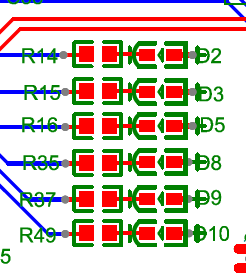
板子设计预留了六个LED灯,起初准备直接注册一个杂项设备进行控制

随后发现Linux内核中自带LED驱动,所以准备研究一下,也就有了这篇文章
Linux 内核自带LED 驱动
Linux 内核已经自带了LED 灯驱动,要使用Linux 内核自带的LED 灯驱动首先得先配置Linux 内核,使能自带的LED 灯驱动,输入如下命令打开Linux 配置菜单:
make menuconfig
按照如下路径打开LED 驱动配置项:
-> Device Drivers
	-> LED Support (NEW_LEDS [=y])
		->LED Support for GPIO connected LEDs
按照上述路径,选择“LED Support for GPIO connected LEDs”,将其编译进Linux 内核,也即是在此选项上按下“Y”键,使此选项前面变为“<*>”,


查看官方说明文档
打开文档Documentation/devicetree/bindings/leds/leds-gpio.txt
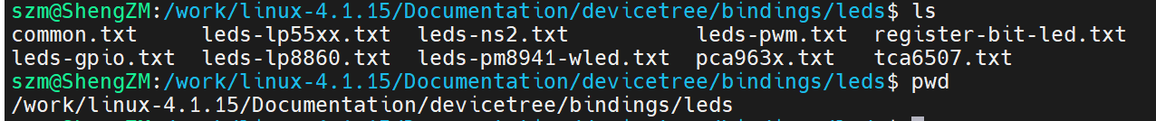
nano ./Documentation/devicetree/bindings/leds/leds-gpio.txt
此文档详细的讲解了Linux 自带驱动对应的设备树节点该如何编写
LEDs connected to GPIO lines

Required properties:
- compatible : should be "gpio-leds".

Each LED is represented as a sub-node of the gpio-leds device.  Each
node's name represents the name of the corresponding LED.

LED sub-node properties:
- gpios :  Should specify the LED's GPIO, see "gpios property" in
  Documentation/devicetree/bindings/gpio/gpio.txt.  Active low LEDs should be
  indicated using flags in the GPIO specifier.
- label :  (optional)
  see Documentation/devicetree/bindings/leds/common.txt
- linux,default-trigger :  (optional)
  see Documentation/devicetree/bindings/leds/common.txt
- default-state:  (optional) The initial state of the LED.  Valid
  values are "on", "off", and "keep".  If the LED is already on or off
  and the default-state property is set the to same value, then no
  glitch should be produced where the LED momentarily turns off (or
  on).  The "keep" setting will keep the LED at whatever its current
  state is, without producing a glitch.  The default is off if this
  property is not present.
- retain-state-suspended: (optional) The suspend state can be retained.Such
  as charge-led gpio.

Examples:

#include <dt-bindings/gpio/gpio.h>

leds {
	compatible = "gpio-leds";
	hdd {
		label = "IDE Activity";
		gpios = <&mcu_pio 0 GPIO_ACTIVE_LOW>;
		linux,default-trigger = "ide-disk";
	};

	fault {
		gpios = <&mcu_pio 1 GPIO_ACTIVE_HIGH>;
		/* Keep LED on if BIOS detected hardware fault */
		default-state = "keep";
	};
};

run-control {
	compatible = "gpio-leds";
	red {
		gpios = <&mpc8572 6 GPIO_ACTIVE_HIGH>;
		default-state = "off";
	};
	green {
		gpios = <&mpc8572 7 GPIO_ACTIVE_HIGH>;
		default-state = "on";
	};
};

leds {
	compatible = "gpio-leds";

	charger-led {
		gpios = <&gpio1 2 GPIO_ACTIVE_HIGH>;
		linux,default-trigger = "max8903-charger-charging";
		retain-state-suspended;
	};
};
对于该说明文档的解析:
①Required properties(必选)
Required properties:
-compatible : should be “gpio-leds”.
Each LED is represented as a sub-node of the gpio-leds device. Each node’s name represents the name of the corresponding LED.
dtsleds 节点的compatible 属性值一定要为 “gpio-leds”
②gpios(必选)
gpios : Should specify the LED’s GPIO, see “gpios property” in Documentation/devicetree/bindings/gpio/gpio.txt. Active low LEDs should be indicated using flags in the GPIO specifier.
gpios :创建一个节点表示LED 灯设备,比如dtsleds,如果板子上有多个LED 灯的话每个LED灯都作为dtsleds 的子节点。也就是每个LED表示为“gpio-leds”的一个子节点。
每个子节点设置gpios 属性值,表示此LED 所使用的GPIO 引脚!
具体gpios的属性设置,详情需要查看文档 Documentation/devicetree/bindings/gpio/gpio.txtLED的高低电平使用GPIO说明中的flag表示
GPIO说明文档
Specifying GPIO information for devices
============================================

1) gpios property
-----------------

Nodes that makes use of GPIOs should specify them using one or more
properties, each containing a 'gpio-list':

	gpio-list ::= <single-gpio> [gpio-list]
	single-gpio ::= <gpio-phandle> <gpio-specifier>
	gpio-phandle : phandle to gpio controller node
	gpio-specifier : Array of #gpio-cells specifying specific gpio
			 (controller specific)

GPIO properties should be named "[<name>-]gpios", with <name> being the purpose
of this GPIO for the device. While a non-existent <name> is considered valid
for compatibility reasons (resolving to the "gpios" property), it is not allowed
for new bindings.

GPIO properties can contain one or more GPIO phandles, but only in exceptional
cases should they contain more than one. If your device uses several GPIOs with
distinct functions, reference each of them under its own property, giving it a
meaningful name. The only case where an array of GPIOs is accepted is when
several GPIOs serve the same function (e.g. a parallel data line).

The exact purpose of each gpios property must be documented in the device tree
binding of the device.

The following example could be used to describe GPIO pins used as device enable
and bit-banged data signals:

	gpio1: gpio1 {
		gpio-controller
		 #gpio-cells = <2>;
	};
	gpio2: gpio2 {
		gpio-controller
		 #gpio-cells = <1>;
	};
	[...]

	enable-gpios = <&gpio2 2>;
	data-gpios = <&gpio1 12 0>,
		     <&gpio1 13 0>,
		     <&gpio1 14 0>,
		     <&gpio1 15 0>;

Note that gpio-specifier length is controller dependent.  In the
above example, &gpio1 uses 2 cells to specify a gpio, while &gpio2
only uses one.

gpio-specifier may encode: bank, pin position inside the bank,
whether pin is open-drain and whether pin is logically inverted.
Exact meaning of each specifier cell is controller specific, and must
be documented in the device tree binding for the device. Use the macros
defined in include/dt-bindings/gpio/gpio.h whenever possible:

Example of a node using GPIOs:

	node {
		enable-gpios = <&qe_pio_e 18 GPIO_ACTIVE_HIGH>;
	};

GPIO_ACTIVE_HIGH is 0, so in this example gpio-specifier is "18 0" and encodes
GPIO pin number, and GPIO flags as accepted by the "qe_pio_e" gpio-controller.

1.1) GPIO specifier best practices
----------------------------------

A gpio-specifier should contain a flag indicating the GPIO polarity; active-
high or active-low. If it does, the following best practices should be
followed:

The gpio-specifier's polarity flag should represent the physical level at the
GPIO controller that achieves (or represents, for inputs) a logically asserted
value at the device. The exact definition of logically asserted should be
defined by the binding for the device. If the board inverts the signal between
the GPIO controller and the device, then the gpio-specifier will represent the
opposite physical level than the signal at the device's pin.

When the device's signal polarity is configurable, the binding for the
device must either:

a) Define a single static polarity for the signal, with the expectation that
any software using that binding would statically program the device to use
that signal polarity.

The static choice of polarity may be either:

a1) (Preferred) Dictated by a binding-specific DT property.

or:

a2) Defined statically by the DT binding itself.

In particular, the polarity cannot be derived from the gpio-specifier, since
that would prevent the DT from separately representing the two orthogonal
concepts of configurable signal polarity in the device, and possible board-
level signal inversion.

or:

b) Pick a single option for device signal polarity, and document this choice
in the binding. The gpio-specifier should represent the polarity of the signal
(at the GPIO controller) assuming that the device is configured for this
particular signal polarity choice. If software chooses to program the device
to generate or receive a signal of the opposite polarity, software will be
responsible for correctly interpreting (inverting) the GPIO signal at the GPIO
controller.

2) gpio-controller nodes
------------------------

Every GPIO controller node must contain both an empty "gpio-controller"
property, and a #gpio-cells integer property, which indicates the number of
cells in a gpio-specifier.

The GPIO chip may contain GPIO hog definitions. GPIO hogging is a mechanism
providing automatic GPIO request and configuration as part of the
gpio-controller's driver probe function.

Each GPIO hog definition is represented as a child node of the GPIO controller.
Required properties:
- gpio-hog:   A property specifying that this child node represent a GPIO hog.
- gpios:      Store the GPIO information (id, flags, ...). Shall contain the
	      number of cells specified in its parent node (GPIO controller
	      node).
Only one of the following properties scanned in the order shown below.
This means that when multiple properties are present they will be searched
in the order presented below and the first match is taken as the intended
configuration.
- input:      A property specifying to set the GPIO direction as input.
- output-low  A property specifying to set the GPIO direction as output with
	      the value low.
- output-high A property specifying to set the GPIO direction as output with
	      the value high.

Optional properties:
- line-name:  The GPIO label name. If not present the node name is used.

Example of two SOC GPIO banks defined as gpio-controller nodes:

	qe_pio_a: gpio-controller@1400 {
		compatible = "fsl,qe-pario-bank-a", "fsl,qe-pario-bank";
		reg = <0x1400 0x18>;
		gpio-controller;
		#gpio-cells = <2>;

		line_b {
			gpio-hog;
			gpios = <6 0>;
			output-low;
			line-name = "foo-bar-gpio";
		};
	};

	qe_pio_e: gpio-controller@1460 {
		compatible = "fsl,qe-pario-bank-e", "fsl,qe-pario-bank";
		reg = <0x1460 0x18>;
		gpio-controller;
		#gpio-cells = <2>;
	};

2.1) gpio- and pin-controller interaction
-----------------------------------------

Some or all of the GPIOs provided by a GPIO controller may be routed to pins
on the package via a pin controller. This allows muxing those pins between
GPIO and other functions.

It is useful to represent which GPIOs correspond to which pins on which pin
controllers. The gpio-ranges property described below represents this, and
contains information structures as follows:

	gpio-range-list ::= <single-gpio-range> [gpio-range-list]
	single-gpio-range ::= <numeric-gpio-range> | <named-gpio-range>
	numeric-gpio-range ::=
			<pinctrl-phandle> <gpio-base> <pinctrl-base> <count>
	named-gpio-range ::= <pinctrl-phandle> <gpio-base> '<0 0>'
	pinctrl-phandle : phandle to pin controller node
	gpio-base : Base GPIO ID in the GPIO controller
	pinctrl-base : Base pinctrl pin ID in the pin controller
	count : The number of GPIOs/pins in this range

The "pin controller node" mentioned above must conform to the bindings
described in ../pinctrl/pinctrl-bindings.txt.

In case named gpio ranges are used (ranges with both <pinctrl-base> and
<count> set to 0), the property gpio-ranges-group-names contains one string
for every single-gpio-range in gpio-ranges:
	gpiorange-names-list ::= <gpiorange-name> [gpiorange-names-list]
	gpiorange-name : Name of the pingroup associated to the GPIO range in
			the respective pin controller.

Elements of gpiorange-names-list corresponding to numeric ranges contain
the empty string. Elements of gpiorange-names-list corresponding to named
ranges contain the name of a pin group defined in the respective pin
controller. The number of pins/GPIOs in the range is the number of pins in
that pin group.

Previous versions of this binding required all pin controller nodes that
were referenced by any gpio-ranges property to contain a property named
#gpio-range-cells with value <3>. This requirement is now deprecated.
However, that property may still exist in older device trees for
compatibility reasons, and would still be required even in new device
trees that need to be compatible with older software.

Example 1:

	qe_pio_e: gpio-controller@1460 {
		#gpio-cells = <2>;
		compatible = "fsl,qe-pario-bank-e", "fsl,qe-pario-bank";
		reg = <0x1460 0x18>;
		gpio-controller;
		gpio-ranges = <&pinctrl1 0 20 10>, <&pinctrl2 10 50 20>;
	};

Here, a single GPIO controller has GPIOs 0..9 routed to pin controller
pinctrl1's pins 20..29, and GPIOs 10..19 routed to pin controller pinctrl2's
pins 50..59.

Example 2:

	gpio_pio_i: gpio-controller@14B0 {
		#gpio-cells = <2>;
		compatible = "fsl,qe-pario-bank-e", "fsl,qe-pario-bank";
		reg = <0x1480 0x18>;
		gpio-controller;
		gpio-ranges =			<&pinctrl1 0 20 10>,
						<&pinctrl2 10 0 0>,
						<&pinctrl1 15 0 10>,
						<&pinctrl2 25 0 0>;
		gpio-ranges-group-names =	"",
						"foo",
						"",
						"bar";
	};

Here, three GPIO ranges are defined wrt. two pin controllers. pinctrl1 GPIO
ranges are defined using pin numbers whereas the GPIO ranges wrt. pinctrl2
are named "foo" and "bar".
文档中找到了我们关心的flag定义,我们可以明确flag对应的定义在 include/dt-bindings/gpio/gpio.h 中
打开文档
nano include/dt-bindings/gpio/gpio.h
/*
 * This header provides constants for most GPIO bindings.
 *
 * Most GPIO bindings include a flags cell as part of the GPIO specifier.
 * In most cases, the format of the flags cell uses the standard values
 * defined in this header.
 */

#ifndef _DT_BINDINGS_GPIO_GPIO_H
#define _DT_BINDINGS_GPIO_GPIO_H

#define GPIO_ACTIVE_HIGH 0
#define GPIO_ACTIVE_LOW 1

#endif
③label(可选)
label : (optional) see Documentation/devicetree/bindings/leds/common.txt
设置label 属性,此属性为可选,每个子节点都有一个label 属性,label 属性一般表示LED 灯的名字,比如以颜色区分的话就是red、green 等等。具体属性打开文件Documentation/devicetree/bindings/leds/common.txt查看
nano Documentation/devicetree/bindings/leds/common.txt
Common leds properties.

LED and flash LED devices provide the same basic functionality as current
regulators, but extended with LED and flash LED specific features like
blinking patterns, flash timeout, flash faults and external flash strobe mode.

Many LED devices expose more than one current output that can be connected
to one or more discrete LED component. Since the arrangement of connections
can influence the way of the LED device initialization, the LED components
have to be tightly coupled with the LED device binding. They are represented
by child nodes of the parent LED device binding.

Optional properties for child nodes:
- led-sources : List of device current outputs the LED is connected to. The
		outputs are identified by the numbers that must be defined
		in the LED device binding documentation.
- label : The label for this LED. If omitted, the label is taken from the node
	  name (excluding the unit address). It has to uniquely identify
	  a device, i.e. no other LED class device can be assigned the same
	  label.

- linux,default-trigger :  This parameter, if present, is a
    string defining the trigger assigned to the LED.  Current triggers are:
     "backlight" - LED will act as a back-light, controlled by the framebuffer
		   system
     "default-on" - LED will turn on (but for leds-gpio see "default-state"
		    property in Documentation/devicetree/bindings/gpio/led.txt)
     "heartbeat" - LED "double" flashes at a load average based rate
     "ide-disk" - LED indicates disk activity
     "timer" - LED flashes at a fixed, configurable rate

- max-microamp : maximum intensity in microamperes of the LED
		 (torch LED for flash devices)
- flash-max-microamp : maximum intensity in microamperes of the
                       flash LED; it is mandatory if the LED should
		       support the flash mode
- flash-timeout-us : timeout in microseconds after which the flash
                     LED is turned off


Examples:

system-status {
	label = "Status";
	linux,default-trigger = "heartbeat";
	...
};

camera-flash {
	label = "Flash";
	led-sources = <0>, <1>;
	max-microamp = <50000>;
	flash-max-microamp = <320000>;
	flash-timeout-us = <500000>;
};
④linux,default-trigger(可选)
可以设置**“linux,default-trigger”**属性值,也就是设置LED 灯的默认功能,可以查阅
Documentation/devicetree/bindings/leds/common.txt 这个文档来查看可选功能,比如:
backlight:LED 灯作为背光。
default-on:LED 灯打开
heartbeat:LED 灯作为心跳指示灯,可以作为系统运行提示灯。
ide-disk:LED 灯作为硬盘活动指示灯。
timer:LED 灯周期性闪烁,由定时器驱动,闪烁频率可以修改
⑤default-state(可选)
可以设置“default-state”属性值,可以设置为on、off 或keep,为on 的时候LED 灯默
认打开,为off 的话LED 灯默认关闭,为keep 的话LED 灯保持当前模式。
⑥retain-state-suspended(可选)
retain-state-suspended: (Optional) You can retain the suspended state. such as a charge-dominated gpio.
Linux的LED子系统源码
drivers/leds/*
从drivers/leds/Makefile中
# LED Core
obj-$(CONFIG_NEW_LEDS)			+= led-core.o
obj-$(CONFIG_LEDS_CLASS)		+= led-class.o
obj-$(CONFIG_LEDS_CLASS_FLASH)		+= led-class-flash.o
obj-$(CONFIG_LEDS_TRIGGERS)		+= led-triggers.o

# LED Platform Drivers
obj-$(CONFIG_LEDS_88PM860X)		+= leds-88pm860x.o
obj-$(CONFIG_LEDS_BD2802)		+= leds-bd2802.o
obj-$(CONFIG_LEDS_LOCOMO)		+= leds-locomo.o
obj-$(CONFIG_LEDS_LM3530)		+= leds-lm3530.o
obj-$(CONFIG_LEDS_LM3533)		+= leds-lm3533.o
obj-$(CONFIG_LEDS_LM3642)		+= leds-lm3642.o
obj-$(CONFIG_LEDS_MIKROTIK_RB532)	+= leds-rb532.o
obj-$(CONFIG_LEDS_S3C24XX)		+= leds-s3c24xx.o
obj-$(CONFIG_LEDS_NET48XX)		+= leds-net48xx.o
obj-$(CONFIG_LEDS_WRAP)			+= leds-wrap.o
obj-$(CONFIG_LEDS_COBALT_QUBE)		+= leds-cobalt-qube.o
obj-$(CONFIG_LEDS_COBALT_RAQ)		+= leds-cobalt-raq.o
obj-$(CONFIG_LEDS_SUNFIRE)		+= leds-sunfire.o
obj-$(CONFIG_LEDS_PCA9532)		+= leds-pca9532.o
obj-$(CONFIG_LEDS_GPIO_REGISTER)	+= leds-gpio-register.o
obj-$(CONFIG_LEDS_GPIO)			+= leds-gpio.o
obj-$(CONFIG_LEDS_LP3944)		+= leds-lp3944.o
obj-$(CONFIG_LEDS_LP55XX_COMMON)	+= leds-lp55xx-common.o
obj-$(CONFIG_LEDS_LP5521)		+= leds-lp5521.o
obj-$(CONFIG_LEDS_LP5523)		+= leds-lp5523.o
obj-$(CONFIG_LEDS_LP5562)		+= leds-lp5562.o
obj-$(CONFIG_LEDS_LP8501)		+= leds-lp8501.o
obj-$(CONFIG_LEDS_LP8788)		+= leds-lp8788.o
obj-$(CONFIG_LEDS_LP8860)		+= leds-lp8860.o
obj-$(CONFIG_LEDS_TCA6507)		+= leds-tca6507.o
obj-$(CONFIG_LEDS_CLEVO_MAIL)		+= leds-clevo-mail.o
obj-$(CONFIG_LEDS_IPAQ_MICRO)		+= leds-ipaq-micro.o
obj-$(CONFIG_LEDS_HP6XX)		+= leds-hp6xx.o
obj-$(CONFIG_LEDS_OT200)		+= leds-ot200.o
obj-$(CONFIG_LEDS_FSG)			+= leds-fsg.o
obj-$(CONFIG_LEDS_PCA955X)		+= leds-pca955x.o
obj-$(CONFIG_LEDS_PCA963X)		+= leds-pca963x.o
obj-$(CONFIG_LEDS_DA903X)		+= leds-da903x.o
obj-$(CONFIG_LEDS_DA9052)		+= leds-da9052.o
obj-$(CONFIG_LEDS_WM831X_STATUS)	+= leds-wm831x-status.o
obj-$(CONFIG_LEDS_WM8350)		+= leds-wm8350.o
obj-$(CONFIG_LEDS_PWM)			+= leds-pwm.o
obj-$(CONFIG_LEDS_REGULATOR)		+= leds-regulator.o
obj-$(CONFIG_LEDS_INTEL_SS4200)		+= leds-ss4200.o
obj-$(CONFIG_LEDS_LT3593)		+= leds-lt3593.o
obj-$(CONFIG_LEDS_ADP5520)		+= leds-adp5520.o
obj-$(CONFIG_LEDS_DELL_NETBOOKS)	+= dell-led.o
obj-$(CONFIG_LEDS_MC13783)		+= leds-mc13783.o
obj-$(CONFIG_LEDS_NS2)			+= leds-ns2.o
obj-$(CONFIG_LEDS_NETXBIG)		+= leds-netxbig.o
obj-$(CONFIG_LEDS_ASIC3)		+= leds-asic3.o
obj-$(CONFIG_LEDS_MAX8997)		+= leds-max8997.o
obj-$(CONFIG_LEDS_LM355x)		+= leds-lm355x.o
obj-$(CONFIG_LEDS_BLINKM)		+= leds-blinkm.o
obj-$(CONFIG_LEDS_SYSCON)		+= leds-syscon.o
obj-$(CONFIG_LEDS_VERSATILE)		+= leds-versatile.o
obj-$(CONFIG_LEDS_MENF21BMC)		+= leds-menf21bmc.o
obj-$(CONFIG_LEDS_PM8941_WLED)		+= leds-pm8941-wled.o

# LED SPI Drivers
obj-$(CONFIG_LEDS_DAC124S085)		+= leds-dac124s085.o

# LED Triggers
obj-$(CONFIG_LEDS_TRIGGERS)		+= trigger/
可以看到LED子系统的主要文件有几类:
LED核心:leds.h、led-core.c、led-class.c、led-triggers.c(其中led-triggers又分为了timer、ide-disk、heartbeat、backlight、gpio、default-on等)
应用LED的各种Drivers:基于Platform平台总线,SPI总线的应用

include/linux/leds.h

其中Led的亮度,分为三等级,关、中间、最亮。
enum led_brightness {
	LED_OFF		= 0,
	LED_HALF	= 127,
	LED_FULL	= 255,
};
led_classdev 结构:
struct led_classdev {
	const char		*name;// Led的名字
	enum led_brightness	 brightness;//Led亮度
	enum led_brightness	 max_brightness;//led最大亮度
	int			 flags;

	/* Lower 16 bits reflect status */
#define LED_SUSPENDED		(1 << 0)
	/* Upper 16 bits reflect control information */
#define LED_CORE_SUSPENDRESUME	(1 << 16)
#define LED_BLINK_ONESHOT	(1 << 17)
#define LED_BLINK_ONESHOT_STOP	(1 << 18)
#define LED_BLINK_INVERT	(1 << 19)
#define LED_SYSFS_DISABLE	(1 << 20)
#define SET_BRIGHTNESS_ASYNC	(1 << 21)
#define SET_BRIGHTNESS_SYNC	(1 << 22)
#define LED_DEV_CAP_FLASH	(1 << 23)

	/* Set LED brightness level */
	/* Must not sleep, use a workqueue if needed */
	void		(*brightness_set)(struct led_classdev *led_cdev,
					  enum led_brightness brightness);
	/*
	 * Set LED brightness level immediately - it can block the caller for
	 * the time required for accessing a LED device register.
	 */
	int		(*brightness_set_sync)(struct led_classdev *led_cdev,
					enum led_brightness brightness); // 用于设置亮度的函数指针
	/* Get LED brightness level */
	enum led_brightness (*brightness_get)(struct led_classdev *led_cdev);// 用于获取亮度的函数指针

	/*
	 * Activate hardware accelerated blink, delays are in milliseconds
	 * and if both are zero then a sensible default should be chosen.
	 * The call should adjust the timings in that case and if it can't
	 * match the values specified exactly.
	 * Deactivate blinking again when the brightness is set to a fixed
	 * value via the brightness_set() callback.
	 */
	int		(*blink_set)(struct led_classdev *led_cdev,
				     unsigned long *delay_on,
				     unsigned long *delay_off);// 用来设置闪烁时点亮和熄灭时长

	struct device		*dev;
	const struct attribute_group	**groups;

	struct list_head	 node;			/* LED Device list LED设备链表*/
    const char      *default_trigger;   /* Trigger to use 该led_classdev使用的trigger的名字,通过这个名字在trigger_list中找到对应的trigger */

	unsigned long		 blink_delay_on, blink_delay_off;// 闪烁的开关时间
	struct timer_list	 blink_timer;// 闪烁的定时器链表
	int			 blink_brightness;// 闪烁的亮度
	void			(*flash_resume)(struct led_classdev *led_cdev);

	struct work_struct	set_brightness_work;
	int			delayed_set_value;

#ifdef CONFIG_LEDS_TRIGGERS
	/* Protects the trigger data below */
	struct rw_semaphore	 trigger_lock; // trigger的锁

	struct led_trigger	*trigger;// Led的trigger
	struct list_head	 trig_list;// trigger链表
	void			*trigger_data;// trigger数据
	/* true if activated - deactivate routine uses it to do cleanup */
	bool			activated;
#endif

	/* Ensures consistent access to the LED Flash Class device */
	struct mutex		led_access;
};
led_trigger 结构
/*
 * LED Triggers
 */
/* Registration functions for simple triggers */
#define DEFINE_LED_TRIGGER(x)		static struct led_trigger *x;
#define DEFINE_LED_TRIGGER_GLOBAL(x)	struct led_trigger *x;

#ifdef CONFIG_LEDS_TRIGGERS

#define TRIG_NAME_MAX 50

struct led_trigger {
	/* Trigger Properties */
	const char	 *name;
	void		(*activate)(struct led_classdev *led_cdev);
	void		(*deactivate)(struct led_classdev *led_cdev);

	/* LEDs under control by this trigger (for simple triggers) */
	rwlock_t	  leddev_list_lock;
	struct list_head  led_cdevs;

	/* Link to next registered trigger */
	struct list_head  next_trig;
};
gpio_led 结构适用于leds-gpio.c:
/* For the leds-gpio driver */
struct gpio_led {
	const char *name;
	const char *default_trigger;
	unsigned 	gpio;
	unsigned	active_low : 1;
	unsigned	retain_state_suspended : 1;
	unsigned	default_state : 2;
	/* default_state should be one of LEDS_GPIO_DEFSTATE_(ON|OFF|KEEP) */
	struct gpio_desc *gpiod;
};
#define LEDS_GPIO_DEFSTATE_OFF		0
#define LEDS_GPIO_DEFSTATE_ON		1
#define LEDS_GPIO_DEFSTATE_KEEP		2

struct gpio_led_platform_data {
	int 		num_leds;
	const struct gpio_led *leds;

#define GPIO_LED_NO_BLINK_LOW	0	/* No blink GPIO state low */
#define GPIO_LED_NO_BLINK_HIGH	1	/* No blink GPIO state high */
#define GPIO_LED_BLINK		2	/* Please, blink */
	int		(*gpio_blink_set)(struct gpio_desc *desc, int state,
					unsigned long *delay_on,
					unsigned long *delay_off);
};
子系统中的trigger
ledtrig-default-on.c
用于设置led为最大亮度
static int __init defon_trig_init(void)
{
    return led_trigger_register(&defon_led_trigger);
}
static struct led_trigger defon_led_trigger = {
    .name     = "default-on",
    .activate = defon_trig_activate,
};
static void defon_trig_activate(struct led_classdev *led_cdev)
{
    // 设置led为最大亮度
    led_set_brightness(led_cdev, led_cdev->max_brightness);
}
// drivers/leds/leds.h
static inline void led_set_brightness(struct led_classdev *led_cdev,
                    enum led_brightness value)
{
    if (value > led_cdev->max_brightness)
        value = led_cdev->max_brightness;
    led_cdev->brightness = value;
    if (!(led_cdev->flags & LED_SUSPENDED))
        // 设置亮度
        led_cdev->brightness_set(led_cdev, value);
}
ledtrig-backlight.c
struct bl_trig_notifier {
    struct led_classdev *led;  //led子系统设备
    int brightness; //亮度
    int old_status;
    struct notifier_block notifier; //内核通知链
    unsigned invert; //反转
};
模块初始化,注册bl_led_trigger
static int __init bl_trig_init(void)
{
    return led_trigger_register(&bl_led_trigger);
}
bl_led_trigger映射
static struct led_trigger bl_led_trigger = {
    .name       = "backlight",
    .activate   = bl_trig_activate,//激活backlight的trigger时调用
    .deactivate = bl_trig_deactivate//关闭backlight的trigger时调用
};
activate操作函数
- 分配一个bl_trig_notifier结构
- device_create_file创建设备文件
- 设置bl_trig_notifier结构
- fb_register_client将n->notifier注册到framebuffer中的fb_notifier_list中,一旦framebuffer驱动中有事件,就会调用内核通知链中注册好的函数fb_notifier_callback
ledtrig-timer.c
static int __init timer_trig_init(void)
{
    return led_trigger_register(&timer_led_trigger);
}
创建一个led_trigger并映射:
static struct led_trigger timer_led_trigger = {
    .name     = "timer",
    .activate = timer_trig_activate,
    .deactivate = timer_trig_deactivate,
};
当某个led_classdev与之连接后,激活timer_led_trigger 时(通过echo timer > /sys/class/leds/led1/trigger)调用timer_trig_activate:
- 这个触发器会在/sys/class/leds//下创建两个文件delay_on和delay_off,用户空间往这两个文件中写入数据后,相应的led会按照设置的高低电平的时间(ms)来闪烁。
- 如果led_classdev注册了硬件闪烁的接口led_cdev->blink_set就是用硬件控制闪烁,否则用软件定时器来控制闪烁。
static DEVICE_ATTR(delay_on, 0666, led_delay_on_show, led_delay_on_store);
static DEVICE_ATTR(delay_off, 0666, led_delay_off_show, led_delay_off_store);

static void timer_trig_activate(struct led_classdev *led_cdev)
{
    int rc;

    led_cdev->trigger_data = NULL;

    rc = device_create_file(led_cdev->dev, &dev_attr_delay_on);
    if (rc)
        return;
    rc = device_create_file(led_cdev->dev, &dev_attr_delay_off);
    if (rc)
        goto err_out_delayon;

    led_blink_set(led_cdev, &led_cdev->blink_delay_on,
              &led_cdev->blink_delay_off);

    led_cdev->trigger_data = (void *)1;

    return;

err_out_delayon:
    device_remove_file(led_cdev->dev, &dev_attr_delay_on);
}
ledtrig-heartbeat.c
通过定时来实现类似于心跳的led灯。
struct heartbeat_trig_data {
    unsigned int phase;
    unsigned int period;
    struct timer_list timer;
};
static struct led_trigger heartbeat_led_trigger = {
    .name     = "heartbeat",
    .activate = heartbeat_trig_activate,
    .deactivate = heartbeat_trig_deactivate,
};
static void heartbeat_trig_activate(struct led_classdev *led_cdev)
{
    struct heartbeat_trig_data *heartbeat_data;

    heartbeat_data = kzalloc(sizeof(*heartbeat_data), GFP_KERNEL);
    if (!heartbeat_data)
        return;

    led_cdev->trigger_data = heartbeat_data;
    setup_timer(&heartbeat_data->timer,
            led_heartbeat_function, (unsigned long) led_cdev);
    heartbeat_data->phase = 0;
    led_heartbeat_function(heartbeat_data->timer.data);
}
设置了heartbeat_data->phase,然后调用led_heartbeat_function。
static void led_heartbeat_function(unsigned long data)
{
    struct led_classdev *led_cdev = (struct led_classdev *) data;
    struct heartbeat_trig_data *heartbeat_data = led_cdev->trigger_data;
    unsigned long brightness = LED_OFF;
    unsigned long delay = 0;

    /* acts like an actual heart beat -- ie thump-thump-pause... */
    switch (heartbeat_data->phase) {
    case 0:
        /*
         * The hyperbolic function below modifies the
         * heartbeat period length in dependency of the
         * current (1min) load. It goes through the points
         * f(0)=1260, f(1)=860, f(5)=510, f(inf)->300.
         */
        heartbeat_data->period = 300 +
            (6720 << FSHIFT) / (5 * avenrun[0] + (7 << FSHIFT));
        heartbeat_data->period =
            msecs_to_jiffies(heartbeat_data->period);
        delay = msecs_to_jiffies(70);
        heartbeat_data->phase++;
        brightness = led_cdev->max_brightness;
        break;
    case 1:
        delay = heartbeat_data->period / 4 - msecs_to_jiffies(70);
        heartbeat_data->phase++;
        break;
    case 2:
        delay = msecs_to_jiffies(70);
        heartbeat_data->phase++;
        brightness = led_cdev->max_brightness;
        break;
    default:
        delay = heartbeat_data->period - heartbeat_data->period / 4 -
            msecs_to_jiffies(70);
        heartbeat_data->phase = 0;
        break;
    }

    led_set_brightness(led_cdev, brightness);
    mod_timer(&heartbeat_data->timer, jiffies + delay);
}
ledtrig-ide-disk.c
通过定时器实现类似于硬盘灯的指示。
static int __init ledtrig_ide_init(void)
{
    led_trigger_register_simple("ide-disk", &ledtrig_ide);
    return 0;
}
static void ledtrig_ide_timerfunc(unsigned long data)
{
    if (ide_lastactivity != ide_activity) {
        ide_lastactivity = ide_activity;
        /* INT_MAX will set each LED to its maximum brightness */
        led_trigger_event(ledtrig_ide, INT_MAX);
        mod_timer(&ledtrig_ide_timer, jiffies + msecs_to_jiffies(10));
    } else {
        led_trigger_event(ledtrig_ide, LED_OFF);
    }
}
leds-gpio.c驱动源码
打开文件夹
cd drivers/leds

打开文件 leds-gpio.c
nano leds-gpio.c

完整的驱动源码如下:
/*
 * LEDs driver for GPIOs
 *
 * Copyright (C) 2007 8D Technologies inc.
 * Raphael Assenat <raph@8d.com>
 * Copyright (C) 2008 Freescale Semiconductor, Inc.
 *
 * This program is free software; you can redistribute it and/or modify
 * it under the terms of the GNU General Public License version 2 as
 * published by the Free Software Foundation.
 *
 */
#include <linux/err.h>
#include <linux/gpio.h>
#include <linux/gpio/consumer.h>
#include <linux/kernel.h>
#include <linux/leds.h>
#include <linux/module.h>
#include <linux/platform_device.h>
#include <linux/property.h>
#include <linux/slab.h>
#include <linux/workqueue.h>

struct gpio_led_data {
	struct led_classdev cdev;
	struct gpio_desc *gpiod;
	struct work_struct work;
	u8 new_level;
	u8 can_sleep;
	u8 blinking;
	int (*platform_gpio_blink_set)(struct gpio_desc *desc, int state,
			unsigned long *delay_on, unsigned long *delay_off);
};

static void gpio_led_work(struct work_struct *work)
{
	struct gpio_led_data *led_dat =
		container_of(work, struct gpio_led_data, work);

	if (led_dat->blinking) {
		led_dat->platform_gpio_blink_set(led_dat->gpiod,
					led_dat->new_level, NULL, NULL);
		led_dat->blinking = 0;
	} else
		gpiod_set_value_cansleep(led_dat->gpiod, led_dat->new_level);
}

static void gpio_led_set(struct led_classdev *led_cdev,
	enum led_brightness value)
{
	struct gpio_led_data *led_dat =
		container_of(led_cdev, struct gpio_led_data, cdev);
	int level;

	if (value == LED_OFF)
		level = 0;
	else
		level = 1;

	/* Setting GPIOs with I2C/etc requires a task context, and we don't
	 * seem to have a reliable way to know if we're already in one; so
	 * let's just assume the worst.
	 */
	if (led_dat->can_sleep) {
		led_dat->new_level = level;
		schedule_work(&led_dat->work);
	} else {
		if (led_dat->blinking) {
			led_dat->platform_gpio_blink_set(led_dat->gpiod, level,
							 NULL, NULL);
			led_dat->blinking = 0;
		} else
			gpiod_set_value(led_dat->gpiod, level);
	}
}

static int gpio_blink_set(struct led_classdev *led_cdev,
	unsigned long *delay_on, unsigned long *delay_off)
{
	struct gpio_led_data *led_dat =
		container_of(led_cdev, struct gpio_led_data, cdev);

	led_dat->blinking = 1;
	return led_dat->platform_gpio_blink_set(led_dat->gpiod, GPIO_LED_BLINK,
						delay_on, delay_off);
}

static int create_gpio_led(const struct gpio_led *template,
	struct gpio_led_data *led_dat, struct device *parent,
	int (*blink_set)(struct gpio_desc *, int, unsigned long *,
			 unsigned long *))
{
	int ret, state;

	led_dat->gpiod = template->gpiod;
	if (!led_dat->gpiod) {
		/*
		 * This is the legacy code path for platform code that
		 * still uses GPIO numbers. Ultimately we would like to get
		 * rid of this block completely.
		 */
		unsigned long flags = 0;

		/* skip leds that aren't available */
		if (!gpio_is_valid(template->gpio)) {
			dev_info(parent, "Skipping unavailable LED gpio %d (%s)\n",
					template->gpio, template->name);
			return 0;
		}

		if (template->active_low)
			flags |= GPIOF_ACTIVE_LOW;

		ret = devm_gpio_request_one(parent, template->gpio, flags,
					    template->name);
		if (ret < 0)
			return ret;

		led_dat->gpiod = gpio_to_desc(template->gpio);
		if (IS_ERR(led_dat->gpiod))
			return PTR_ERR(led_dat->gpiod);
	}

	led_dat->cdev.name = template->name;
	led_dat->cdev.default_trigger = template->default_trigger;
	led_dat->can_sleep = gpiod_cansleep(led_dat->gpiod);
	led_dat->blinking = 0;
	if (blink_set) {
		led_dat->platform_gpio_blink_set = blink_set;
		led_dat->cdev.blink_set = gpio_blink_set;
	}
	led_dat->cdev.brightness_set = gpio_led_set;
	if (template->default_state == LEDS_GPIO_DEFSTATE_KEEP)
		state = !!gpiod_get_value_cansleep(led_dat->gpiod);
	else
		state = (template->default_state == LEDS_GPIO_DEFSTATE_ON);
	led_dat->cdev.brightness = state ? LED_FULL : LED_OFF;
	if (!template->retain_state_suspended)
		led_dat->cdev.flags |= LED_CORE_SUSPENDRESUME;

	ret = gpiod_direction_output(led_dat->gpiod, state);
	if (ret < 0)
		return ret;

	INIT_WORK(&led_dat->work, gpio_led_work);

	return led_classdev_register(parent, &led_dat->cdev);
}

static void delete_gpio_led(struct gpio_led_data *led)
{
	led_classdev_unregister(&led->cdev);
	cancel_work_sync(&led->work);
}

struct gpio_leds_priv {
	int num_leds;
	struct gpio_led_data leds[];
};

static inline int sizeof_gpio_leds_priv(int num_leds)
{
	return sizeof(struct gpio_leds_priv) +
		(sizeof(struct gpio_led_data) * num_leds);
}

static struct gpio_leds_priv *gpio_leds_create(struct platform_device *pdev)
{
	struct device *dev = &pdev->dev;
	struct fwnode_handle *child;
	struct gpio_leds_priv *priv;
	int count, ret;
	struct device_node *np;

	count = device_get_child_node_count(dev);
	if (!count)
		return ERR_PTR(-ENODEV);

	priv = devm_kzalloc(dev, sizeof_gpio_leds_priv(count), GFP_KERNEL);
	if (!priv)
		return ERR_PTR(-ENOMEM);

	device_for_each_child_node(dev, child) {
		struct gpio_led led = {};
		const char *state = NULL;

		led.gpiod = devm_get_gpiod_from_child(dev, NULL, child);
		if (IS_ERR(led.gpiod)) {
			fwnode_handle_put(child);
			ret = PTR_ERR(led.gpiod);
			goto err;
		}

		np = of_node(child);

		if (fwnode_property_present(child, "label")) {
			fwnode_property_read_string(child, "label", &led.name);
		} else {
			if (IS_ENABLED(CONFIG_OF) && !led.name && np)
				led.name = np->name;
			if (!led.name)
				return ERR_PTR(-EINVAL);
		}
		fwnode_property_read_string(child, "linux,default-trigger",
					    &led.default_trigger);

		if (!fwnode_property_read_string(child, "default-state",
						 &state)) {
			if (!strcmp(state, "keep"))
				led.default_state = LEDS_GPIO_DEFSTATE_KEEP;
			else if (!strcmp(state, "on"))
				led.default_state = LEDS_GPIO_DEFSTATE_ON;
			else
				led.default_state = LEDS_GPIO_DEFSTATE_OFF;
		}

		if (fwnode_property_present(child, "retain-state-suspended"))
			led.retain_state_suspended = 1;

		ret = create_gpio_led(&led, &priv->leds[priv->num_leds++],
				      dev, NULL);
		if (ret < 0) {
			fwnode_handle_put(child);
			goto err;
		}
	}

	return priv;

err:
	for (count = priv->num_leds - 2; count >= 0; count--)
		delete_gpio_led(&priv->leds[count]);
	return ERR_PTR(ret);
}

static const struct of_device_id of_gpio_leds_match[] = {
	{ .compatible = "gpio-leds", },
	{},
};

MODULE_DEVICE_TABLE(of, of_gpio_leds_match);

static int gpio_led_probe(struct platform_device *pdev)
{
	struct gpio_led_platform_data *pdata = dev_get_platdata(&pdev->dev);
	struct gpio_leds_priv *priv;
	int i, ret = 0;

	if (pdata && pdata->num_leds) {
		priv = devm_kzalloc(&pdev->dev,
				sizeof_gpio_leds_priv(pdata->num_leds),
					GFP_KERNEL);
		if (!priv)
			return -ENOMEM;

		priv->num_leds = pdata->num_leds;
		for (i = 0; i < priv->num_leds; i++) {
			ret = create_gpio_led(&pdata->leds[i],
					      &priv->leds[i],
					      &pdev->dev, pdata->gpio_blink_set);
			if (ret < 0) {
				/* On failure: unwind the led creations */
				for (i = i - 1; i >= 0; i--)
					delete_gpio_led(&priv->leds[i]);
				return ret;
			}
		}
	} else {
		priv = gpio_leds_create(pdev);
		if (IS_ERR(priv))
			return PTR_ERR(priv);
	}

	platform_set_drvdata(pdev, priv);

	return 0;
}

static int gpio_led_remove(struct platform_device *pdev)
{
	struct gpio_leds_priv *priv = platform_get_drvdata(pdev);
	int i;

	for (i = 0; i < priv->num_leds; i++)
		delete_gpio_led(&priv->leds[i]);

	return 0;
}

static struct platform_driver gpio_led_driver = {
	.probe		= gpio_led_probe,
	.remove		= gpio_led_remove,
	.driver		= {
		.name	= "leds-gpio",
		.of_match_table = of_gpio_leds_match,
	},
};

module_platform_driver(gpio_led_driver);

MODULE_AUTHOR("Raphael Assenat <raph@8d.com>, Trent Piepho <tpiepho@freescale.com>");
MODULE_DESCRIPTION("GPIO LED driver");
MODULE_LICENSE("GPL");
MODULE_ALIAS("platform:leds-gpio");
注册platform平台驱动
static int __init gpio_led_init(void)
{
    return platform_driver_register(&gpio_led_driver);
}
static struct platform_driver gpio_led_driver = {
    .probe      = gpio_led_probe,
    .remove     = __devexit_p(gpio_led_remove),
    .driver     = {
        .name   = "leds-gpio",
        .owner  = THIS_MODULE,
        .of_match_table = of_gpio_leds_match,
    },
};
在自己的平台下添加platform device,当device和dirver匹配后,就会调用driver的probe函数
static int __devinit gpio_led_probe(struct platform_device *pdev)
{
    // 获取platform_device的数据
    struct gpio_led_platform_data *pdata = pdev->dev.platform_data;
    struct gpio_leds_priv *priv;
    int i, ret = 0;

    if (pdata && pdata->num_leds) {
        priv = kzalloc(sizeof_gpio_leds_priv(pdata->num_leds),
                GFP_KERNEL);
        if (!priv)
            return -ENOMEM;

        priv->num_leds = pdata->num_leds;
        for (i = 0; i < priv->num_leds; i++) {
            // 创建LED
            ret = create_gpio_led(&pdata->leds[i],
                          &priv->leds[i],
                          &pdev->dev, pdata->gpio_blink_set);
            if (ret < 0) {
                /* On failure: unwind the led creations */
                for (i = i - 1; i >= 0; i--)
                    delete_gpio_led(&priv->leds[i]);
                kfree(priv);
                return ret;
            }
        }
    } else {
        priv = gpio_leds_create_of(pdev);
        if (!priv)
            return -ENODEV;
    }

    platform_set_drvdata(pdev, priv);

    return 0;
}
static int __devinit create_gpio_led(const struct gpio_led *template,
    struct gpio_led_data *led_dat, struct device *parent,
    int (*blink_set)(unsigned, int, unsigned long *, unsigned long *))
{
    int ret, state;

    led_dat->gpio = -1;

    /* skip leds that aren't available */
    if (!gpio_is_valid(template->gpio)) {
        printk(KERN_INFO "Skipping unavailable LED gpio %d (%s)\n",
                template->gpio, template->name);
        return 0;
    }
    // 申请gpio
    ret = gpio_request(template->gpio, template->name);
    if (ret < 0)
        return ret;
    // 设置gpio_led_data
    led_dat->cdev.name = template->name;
    led_dat->cdev.default_trigger = template->default_trigger;
    led_dat->gpio = template->gpio;
    led_dat->can_sleep = gpio_cansleep(template->gpio);
    led_dat->active_low = template->active_low;
    led_dat->blinking = 0;
    if (blink_set) {
        led_dat->platform_gpio_blink_set = blink_set;
        led_dat->cdev.blink_set = gpio_blink_set;
    }
    led_dat->cdev.brightness_set = gpio_led_set;
    // 根据gpio的默认状态,设置输出电平
    if (template->default_state == LEDS_GPIO_DEFSTATE_KEEP)
        state = !!gpio_get_value(led_dat->gpio) ^ led_dat->active_low;
    else
        state = (template->default_state == LEDS_GPIO_DEFSTATE_ON);
    led_dat->cdev.brightness = state ? LED_FULL : LED_OFF;
    if (!template->retain_state_suspended)
        led_dat->cdev.flags |= LED_CORE_SUSPENDRESUME;
    // gpio为输出状态,并设置
    ret = gpio_direction_output(led_dat->gpio, led_dat->active_low ^ state);
    if (ret < 0)
        goto err;
    // 初始化工作队列
    INIT_WORK(&led_dat->work, gpio_led_work);
    // 注册led设备
    ret = led_classdev_register(parent, &led_dat->cdev);
    if (ret < 0)
        goto err;

    return 0;
err:
    gpio_free(led_dat->gpio);
    return ret;
}
struct gpio_led_data {
    struct led_classdev cdev;
    unsigned gpio;
    struct work_struct work;
    u8 new_level;
    u8 can_sleep;
    u8 active_low;
    u8 blinking;
    int (*platform_gpio_blink_set)(unsigned gpio, int state,
            unsigned long *delay_on, unsigned long *delay_off);
};
platform设备如何应用?
比如注册了:
Static struct gpio_led gpio_leds[] = {
    {
           .name=”leds”,
           .default_trigger= “timer”,
           .gpio= 30,
           .active_low= 1,
           .default_state= LEDS_GPIO_DEFSTATE_OFF,
    }
};
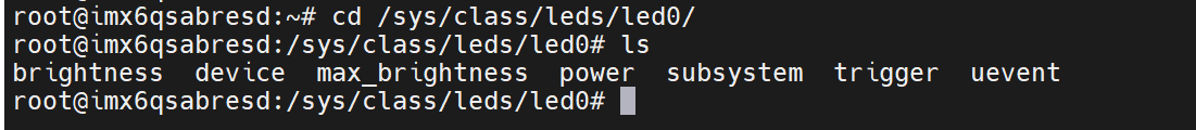
那么在/sys/class/leds/下会有led*目录

在目录中,我们可以看到节点中的六个LED
可以通过指令控制LED高低电平
控制led:
echo 1 > /sys/class/leds/led0/brightness   // label为led0的led灯亮
echo 0 > /sys/class/leds/led0/brightness   // label为led0的led灯灭
调试前准备
在调试阶段,先不在内核中加载驱动,而是取消掉内核驱动,然后单独对其进行编译

将重新编译过的zImage和imx6q-c-sabresd.dtb文件烧录到开发板中启动
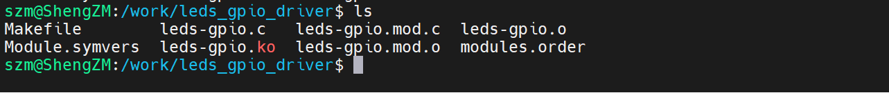
提取原代码的文件,然后写一个Makefile
#	                 ,%%%%%%%%,
#	               ,%%/\%%%%/\%%
#	              ,%%%\c''''J/%%%
#	    %.        %%%%/ o  o \%%%
#	    `%%.      %%%%       |%%%
#	     `%%      `%%%%(__Y__)%%'
#	     //        ;%%%%`\-/%%%'
#	     ((      /   `%%%%%%%'
#	      \\     .'           |
#	       \\   /        \  | |
#	        \\/          ) | |
#	         \          /_ | |__
#	         (____________))))))) 攻城狮

# 调试驱动和应用程序用Makefile

# 编译模块

# 开发板Linux内核的实际路径
# KDIR变量
KDIR:=/work/linux-4.1.15

# 获取当前目录
PWD:=$(shell pwd)

# obj-m表示将 chrdevbase.c这个文件 编译为 .ko模块。
obj-m += leds-gpio.o

# 编译成模块
all:
	make -C $(KDIR) M=$(PWD) modules
clean:
	make -C $(KDIR) M=$(PWD) clean
执行make,这样,就准备好了调试要用的全部内容
添加设备树节点
先来添加设备树节点
根据前面对官方文档的分析
对照板子的硬件设计,添加6个连接到普通GPIO口的led设备树的节点信息
按照良好的添加设备树信息的习惯,首先在设备树文件imx6qdl-sabresd.dtsi中,添加最基础的设备树节点信息
	leds:leds {

		compatible = "gpio-leds";

		led@0 {
			gpios = <&gpio3 16 GPIO_ACTIVE_HIGH>;
		};
		led@1 {
			gpios = <&gpio3 17 GPIO_ACTIVE_HIGH>;
		};
		led@2 {
			gpios = <&gpio3 18 GPIO_ACTIVE_HIGH>;
		};
		led@3 {
			gpios = <&gpio3 19 GPIO_ACTIVE_HIGH>;
		};
		led@4 {
			gpios = <&gpio3 21 GPIO_ACTIVE_HIGH>;
		};
		led@5 {
			gpios = <&gpio3 28 GPIO_ACTIVE_HIGH>;
		};
	};
然后在设备树文件imx6q-c-sabresd.dts中进一步的配置信息,比如,添加默认状态,以及pinctrl子系统,防止设备树中引脚冲突的出现
/*
 * 2020.07.15
 * LED pintrl子系统添加
 */
&leds {

	compatible = "gpio-leds";
	pinctrl-0 = <&pinctrl_gpio_leds>;

	led@0 {
		gpios = <&gpio3 16 GPIO_ACTIVE_HIGH>;
		default-state = "on";
	};
	led@1 {
		gpios = <&gpio3 17 GPIO_ACTIVE_HIGH>;
		default-state = "on";
	};
	led@2 {
		gpios = <&gpio3 18 GPIO_ACTIVE_HIGH>;
		default-state = "on";
	};
	led@3 {
		gpios = <&gpio3 19 GPIO_ACTIVE_HIGH>;
		default-state = "on";
	};
	led@4 {
		gpios = <&gpio3 21 GPIO_ACTIVE_HIGH>;
		default-state = "on";
	};
	led@5 {
		gpios = <&gpio3 28 GPIO_ACTIVE_HIGH>;
		default-state = "on";
	};
};
/*
 * 2020.07.15
 * LED pintrl子系统添加
 */
&pinctrl_gpio_leds {
	fsl,pins = <
		MX6QDL_PAD_EIM_D16__GPIO3_IO16	0x1b0b0
		MX6QDL_PAD_EIM_D17__GPIO3_IO17	0x1b0b0
		MX6QDL_PAD_EIM_D18__GPIO3_IO18	0x1b0b0
		MX6QDL_PAD_EIM_D19__GPIO3_IO19	0x1b0b0
		MX6QDL_PAD_EIM_D21__GPIO3_IO21	0x1b0b0
		MX6QDL_PAD_EIM_D28__GPIO3_IO28	0x1b0b0
	>;
};
修改好设备树之后,我们现在也不知道对不对,需要驱动来一起配合验证
make dtbs -j32

编译,然后烧录进板子最新的dtb文件

下一步就是把led-gpio内核驱动编译成ko模块安装
调试内核驱动
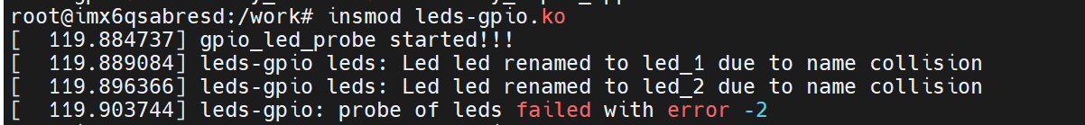
在驱动程序中,首先在驱动中probe函数中加入printk打印信息

将驱动编译成ko模块然后下载到板子

发送到板子中,运行ko文件
果不其然,报错误了
就知道没有这么顺利,那么开始调试吧
错误调试
首先是初步的分析,既然能进入到probe函数,就说明device和drive还有设备树匹配上了,都互相找到了
并且查看lsmod,可以看到驱动模块确实成功加载了
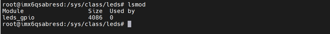
为了更加具体的查看挂载情况,还是要看device和driver
验证device和driver和tree设备树
tree
模块成功安装上了
因为驱动编译成了模块,所以我们可以一步一步的来进行验证,首先就是设备树在系统中的体现,在根文件系统中/proc/device-tree目录下,包括根节点’/’的所有属性和子节点。

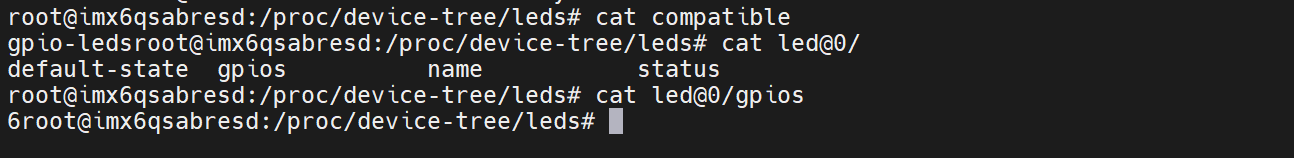
在设备树存放目录arch/arm/boot/dts/中搜索model内容,可以找到对应的.dts文件入口。可以看到model和compatible的属性值完全相同。
device
对于device
打开
/sys/bus/platform/devices

可以看到leds的设备驱动是正常挂载了
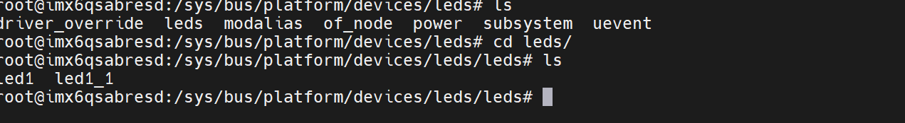
但是,深入打开之后发现,我们的6个led灯设备,在这里只有两个,其他四个都不见了,这个与起初的报错也对应上了
driver
继续查看driver驱动
/sys/bus/platform/drivers

可以看到也是正确挂载了
在卸载ko模块过程中,看到也没有正常打印添加的信息。

到了这里,可以得出一个结论,驱动挂载了,但是并没有完全挂载,应该是设备树出现了问题,但是看设备树驱动,暂时看不出端倪,所以还是要看一看驱动内部究竟发生了什么
驱动源码
开始研究驱动的源码,在源码中添加printk打印,查找驱动出问题的位置
首先是leds-gpio leds: Led led renamed to led_* due to name collision这个错误
错误分析 leds-gpio leds: Led led renamed to led_* due to name collision
在probe函数中,定位到了错误位置

在gpio_leds_create函数中,继续添加更加详细的printk打印信息

可以看到识别到了全部的6个设备树节点,也就是遍历到了全部的设备树节点

打印信息中可以看到,LED0和LED1节点全部都正常初始化,但是后面再一次进入到创建下一个led设备时,进入了err,直接删除了之前注册的设备,这里也就可以解释为什么前面在卸载ko模块时候不会有打印信息,以及平台总线上没有显示全。因为根本就没有加载完成。

修改设备树
虽然在添加设备树过程中,没有看到引脚占用的情况,但是出现了注册不上的情况,很大概率就是某个引脚被占用了,所以没有办法在led驱动中使用
为了验证猜想,一个个的led节点单独测试,最后发现这两个GPIO引脚的问题

注销掉,然后替换GPIO,所有问题都消失了,全部LED正常运行
/*
 * 2020.07.15
 * LED pintrl子系统添加
 */
&leds {
	pinctrl-names = "default";
	pinctrl-0 = <&pinctrl_gpio_leds>;
	fsl,user;

	led@0 {
		label = "led0";
		gpios = <&gpio3 16 GPIO_ACTIVE_HIGH>;
		default-state = "on";
		status = "okay";
	};
	led@1 {
		label = "led1";
		gpios = <&gpio3 17 GPIO_ACTIVE_HIGH>;
		default-state = "on";
		status = "okay";
	};

	led@2 {
		label = "led2";
		gpios = <&gpio3 21 GPIO_ACTIVE_HIGH>;
		default-state = "on";
		status = "okay";
	};
	led@3 {
		label = "led3";
		gpios = <&gpio3 28 GPIO_ACTIVE_HIGH>;
		default-state = "on";
		status = "okay";
	};
	led@4 {
		label = "led4";
		gpios = <&gpio6 6 GPIO_ACTIVE_HIGH>;
		default-state = "on";
		status = "okay";
	};
	led@5 {
		label = "led5";
		gpios = <&gpio5 4 GPIO_ACTIVE_HIGH>;
		default-state = "on";
		status = "okay";
	};

	// led@6 {
	// 	label = "led6";
	// 	gpios = <&gpio2 30 GPIO_ACTIVE_HIGH>;
	// 	default-state = "on";
	// 	status = "okay";
	// };
};
/*
 * 2020.07.15
 * LED pintrl子系统添加
 */
&pinctrl_gpio_leds {
	fsl,pins = <
		MX6QDL_PAD_EIM_D16__GPIO3_IO16  0x1b0b0
		MX6QDL_PAD_EIM_D17__GPIO3_IO17  0x1b0b0
		// MX6QDL_PAD_EIM_D18__GPIO3_IO18  0x1b0b0  // led不可用
		// MX6QDL_PAD_EIM_D19__GPIO3_IO19  0x1b0b0	// led不可用
		MX6QDL_PAD_EIM_D21__GPIO3_IO21  0x1b0b0
		MX6QDL_PAD_EIM_D28__GPIO3_IO28  0x1b0b0

		MX6QDL_PAD_EIM_A23__GPIO6_IO06  0x1b0b0
		MX6QDL_PAD_EIM_A24__GPIO5_IO04  0x1b0b0

		// MX6QDL_PAD_EIM_EB2__GPIO2_IO30  0x1b0b0	// 测试风机GPIO控制正常
	>;
};

卸载ko模块,这时候显示的才是正常的打印信息

测试LED
驱动正常运行了,但是LED能不能正常的控制,我们可以通过一些简单的指令先进行测试
控制led:
echo 1 > /sys/class/leds/led0/brightness // label为led0的led灯亮
echo 0 > /sys/class/leds/led0/brightness // label为led0的led灯灭
正常亮灭!
这里可以理解为在目录/sys/class下放的都是类,比如这个leds就是一个类,下面的就是这个leds类实例化之后的对象,即 led0 led1 led2 led3 led4可以认为是对象,每个对象代表着一个led灯,那么对象的目录下面,即brightness device invert max_brightness power subsystem trigger uevent,这些都是该对象的属性和方法。
<Linux里面一切皆文件,这里也是一文件的方式将内核的接口暴露给用户程序,方便用户程序调用访问>


 2821
2821


 被折叠的 条评论
为什么被折叠?
被折叠的 条评论
为什么被折叠?
 到【灌水乐园】发言


