


下图是大致的硬件连接方式(从另外一个视频借用)
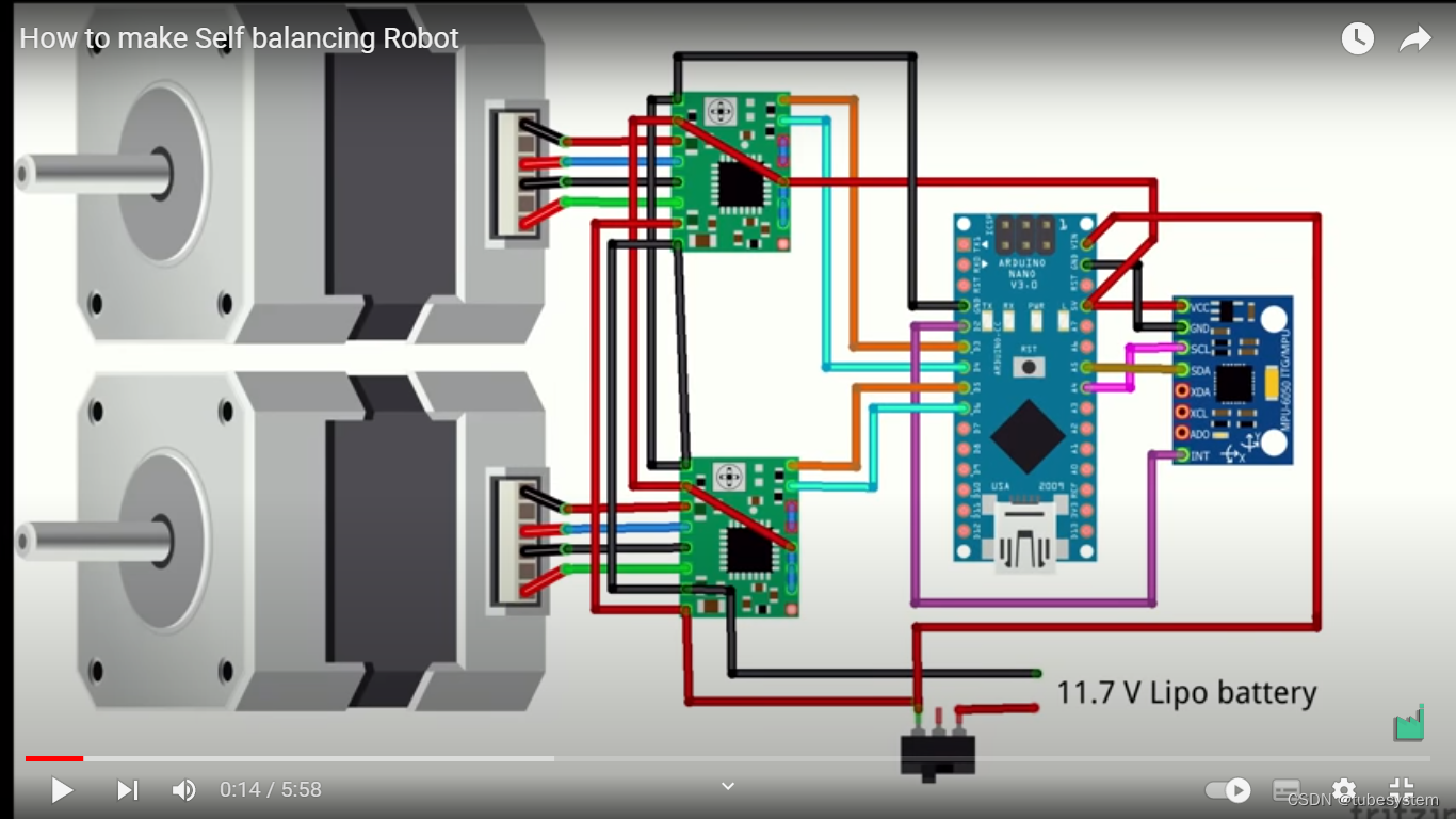
零件清单:
- Arduino Pro Micro timer1和timer3,都是16位的计数器。
- 2个 NEMA 14步进电机(每步1.8度)
- 2个 模型飞机轮毂,轮毂从4毫米到5毫米钻孔并压配到电机轴上
- 2个 步进电机驱动模块
- MPU-6050陀螺仪/加速度计
- 3节LiPo电池
- 蜂鸣器
- LED和几个电阻。
- 一些针头和插座,一些电线和一些热缩管
- 大约20个M3 16 mm螺钉(带螺母)
- 两个用于选择功能的拨动开关
========================================================================
信息来源 from :
Mini balancing robot | Axel's DIY page
https://www.youtube.com/watch?v=egfLymeuGhg
Arduino Mega Balancing Robot | Axel's DIY page
Balancing robot with Raspberry Pi | Axel's DIY page
========================================================================
控制理论 PID的通俗解释
- I 对过去情况的记忆
- P 对现在情况的反应
- D 对未来情况的预测
P 、I 、D 之间的关系
- D积分后是P,P积分后是I。 反过来,I微分后是P,P微分后是D。
- 类似加速度积分后速度,速度积分后是位置。反过来,位置微分后是速度,速度微分后是加速度。
========================================================================
普通的平衡机器人,使用了两个嵌套的PID控制器进行控制。
- 外层PID控制器 ,将电机速度和设定速度之间的差值作为输入,计算出角度(加速度)喂给内层PID。外层回路不需要D部分。外层的积分是位置。主循环(外层PID)400Hz的频率。
- 内层PID控制器 ,获取所需角度和当前角度之间的差值并计算马达的速度。
========================================================================
此外,还有使用了3层PID控制器的平衡小车
外层是位置控制, 具有位置记忆能力,推离后回到原位
中层是速度控制
内层是角度控制(加速度)
========================================================================
系统调参:
一、先调整内层角度PID控制回路。
P部分先调试:将角度设置为0(机器人垂直向上),并将I和D增益设置为0.然后增加P增益直到出现振荡。
I和D部分后调试:然后稍微减少P增益并增加一些I和D增益。当正确完成时机器人应该能够平衡,但会漂移或者被推动。机器人在推动时应该快速地返回垂直状态,并且不应该有高速振荡、振动或大的超调。
二、再调整外层速度PID控制回路。
这通常容易得多,只需添加一些P和I增益并实验即可。
==========================================
数据读取
角度传感器,使用MPU-6050模块,不用MPU计算模块,从传感器读取原始数据,并自己进行传感器融合。陀螺仪和加速度计这两者的结合产生了良好且相对无噪声的角度估计,
- 1、通过积分陀螺仪信号计算角度,“陀螺仪角度”有漂移,不是很准确,“
- 2、然后根据使用加速度计数据计算的另一个角度值以及使用arctan函数的一些基本三角函数稍微调整该角度。加速度计角度”非常嘈杂,并且无法单独使用。
========================================================================
两个辅助开关
数字引脚14.开关用于在静止和前进之间切换,
数字引脚15.开关用于随机转身
========================================================================
arduino程序
当机器人感觉到它的角度接近0(垂直向上)时,机器人将开始平衡。
如果机器人感觉到设定点角度和当前角度之间的角度差太大或者当前角度变得太大(如果机器人在任何方向上倾斜),则平衡机器人将停止。
Arduino还监控电池电压,并在电压过低时停止机器人。
Arduino还监控状态开关,并根据选择开关状态设定机器人状态。
准备
时间△t 周期时间 = 结束时间-开始时间
开始时间
结束时间
角度 = 角度1+角度2
角度1----直接角度读取
角度2----间接角速度积分(陀螺仪)
计算
外层PID
计算P
计算I
计算D
targetAngle = speedPID.updatePID(targetSpeed, motorSpeed , deltaTime) //从目标速度计算加速度
内层PID
计算P
计算I
计算D
motorSpeed = -anglePID.updatePID(targetAngle, currentLeanAngle, deltaTime)//从目标加速度计算电流
输出
轮子的定时器脉冲(是驱动电流脉冲,不是电机步进脉冲)
========================================================================
- // 定义变量
//时间变量
long lastLoopTime = STD_LOOP_TIME;
long lastLoopUsedTime = 0;
unsigned long loopStartTime = 0;
float deltaTime = 0; // unit: seconds
//传感器变量
Mpu6050 imu = Mpu6050(MPU6050_ADDRESS); //角度
ComplementaryFilter angleFilter; //互补( 互余) 过滤器
float voltage = 0; // battery voltage
int randomTurnCounter = 0; // used to make random turns //机器人设置状态变量
// PID 变量
Pid anglePID(ANGLE_P, ANGLE_I, ANGLE_D, ANGLE_I_LIMIT);
Pid speedPID(SPEED_P, SPEED_I, SPEED_D, SPEED_I_LIMIT);
外层P I
内层P I D
//状态变量
boolean balancing = false;
float currentLeanAngle = 0.0f; // float type
float targetAngle
int8_t directionMotor1 = 0;
int8_t directionMotor2 = 0;
float targetSpeed = 0; // drive and turn, unit: wheel revulutions per second轮子旋转频率
float turningSpeed = 0; // 转弯速度--轮子差速
//输出
Buzzer buzzer = Buzzer(BUZZER_PIN); //蜂鸣器
float motorSpeed = 0; // the actual forward/reverce speed of the motors.
=======================================================================
void setup() {
- //子程序,timer1中断的定义,
- //子程序,timer3中断的定义,电机转一个角度
===================================================================================
void loop() {
- // 读,机器人的控制(拨动开关)
void behaviour() {
targetSpeed = 0.5f;
turningSpeed = 0.1f * random(1, 5);
- // 读,惯性传感器
- //读,时间, 计算主循环的使用时间,
lastLoopUsedTime = micros() - loopStartTime; //总时间
if (lastLoopUsedTime < STD_LOOP_TIME) //如果总时间不到设定值就延时
delayMicroseconds(STD_LOOP_TIME - lastLoopUsedTime);
lastLoopTime = micros() - loopStartTime; //延时后的总时间
deltaTime = (float)lastLoopTime / (float)1000000;//从微秒到秒的转换
loopStartTime = micros();
- // 计算, ----初始化状态,角度和速度,
- // 当处于非平衡状态-->加电超过3000微秒-->机器人接近垂直状态-->平衡状态
if (!balancing && millis() > 3000 && abs(currentLeanAngle) < START_ANGLE_ERROR) {
// 初始化机器人
balancing = true;
turningSpeed = 0
motorSpeed = 0;
anglePID.resetPID();
speedPID.resetPID();
buzzer.buzzBlocking(20);
}
- //计算,处于平衡状态, 误差角(目标角度-当前角度)太大(最大误差设定值), 停机
if (balancing) {
// stop balancing if angle error is to large.
if ((targetAngle - MAX_ACCEPTABLE_ANGLE_ERROR) > currentLeanAngle ||
currentLeanAngle > (targetAngle + MAX_ACCEPTABLE_ANGLE_ERROR)) {
balancing = false;
buzzer.buzzBlocking(50);
}
- //计算,处于平衡状态,倾角太大(最大允许设定值), 停机
// stop balancing if the robot is leaning to much in any direction.
if (-MAX_ACCEPTABLE_ANGLE > currentLeanAngle || currentLeanAngle > MAX_ACCEPTABLE_ANGLE) {
balancing = false;
buzzer.buzzBlocking(50);
}
- //计算,俯仰角度
float accAngle = atan2(imu.getAccelY(), imu.getAccelZ()) * 57;
//加速度传感器
// atan2() 函数,其返回值是-π—π,从π转换到度,要除以3.14,再乘以180,系数大约是57
currentLeanAngle = angleFilter.calculate(accAngle,imu.getGyroX(), deltaTime);
//用陀螺仪传感器做简单的互补矫正
- //计算,用PID计算俯仰角度(加速度)和速度
targetAngle = speedPID.updatePID(targetSpeed, motorSpeed , deltaTime);
motorSpeed = -anglePID.updatePID(targetAngle, currentLeanAngle, deltaTime);
/*
atan 和 atan2 都是求反正切函数,如:有两个点 point(x1,y1), 和 point(x2,y2);
float angle = atan( (y2-y1)/(x2-x1) );
float angle = atan2( y2-y1, x2-x1 );
atan2 的优点在于 如果 x2-x1等于0 依然可以计算,但是atan函数就会导致程序出错;*/
- //计算,电机速度,
//输出,电机速度
float leftMotorSpeed = (motorSpeed + turningSpeed) * 3600;
// motor speed is converted from 每秒几圈 to每秒几度
float rightMotorSpeed = (motorSpeed - turningSpeed) * 3600;
setMotorSpeed( leftMotorSpeed, 2); //左电机--2
setMotorSpeed(rightMotorSpeed, 1); //右电机--1
digitalWrite(STEPPER_ENABLE_PIN, LOW); //enable the stepper motors
}
else
{
setMotorSpeed(0, 2); // set the speeds of each motor to zero
setMotorSpeed(0, 1);
digitalWrite(STEPPER_ENABLE_PIN, HIGH); // disable the stepper motors
}
- // 读, 输入子程序的马达转速,
// 计算,
// 输出,电机方向,电机定时器(方波占比)directionMotorX和OCRXA
void setMotorSpeed(int16_t tspeed, int motorID)
{
long timer_period;
int16_t motorspeed = tspeed;
if (motorID == 1) {
if (motorspeed > 0) {
timer_period = 2000000 / motorspeed; // 2Mhz timer
directionMotor1 = 1;
digitalWrite(STEPPER_1_DIR_PIN, LOW);
} else if (motorspeed < 0) {
timer_period = 2000000 / -motorspeed;
directionMotor1 = -1;
digitalWrite(STEPPER_1_DIR_PIN, HIGH);
} else {
timer_period = 65535;
directionMotor1 = 0;
}
if (timer_period > 65535) // Check for maximun period without overflow
timer_period = 65535;
OCR1A = timer_period; // OCR1A保留字 ,不需要声明
if (TCNT1 > OCR1A) // Check if we need to reset the timer...
TCNT1 = 0; // TCNT1 保留字 ,不需要声明
} else if (motorID == 2){
if (motorspeed > 0) {
timer_period = 2000000 / motorspeed; // 2Mhz timer
directionMotor2 = 1;
digitalWrite(STEPPER_2_DIR_PIN, HIGH);
} else if (motorspeed < 0) {
timer_period = 2000000 / -motorspeed;
directionMotor2 = -1;
digitalWrite(STEPPER_2_DIR_PIN, LOW);
} else {
timer_period = 65535;
directionMotor2 = 0;
}
if (timer_period > 65535) // Check for maximun period without overflow
timer_period = 65535;
OCR3A = timer_period;
if (TCNT3 > OCR3A) // Check if we need to reset the timer...
TCNT3 = 0;
}
}
============================================================


 2134
2134


 被折叠的 条评论
为什么被折叠?
被折叠的 条评论
为什么被折叠?
 到【灌水乐园】发言


