


前言
首先请大家思考一个问题,当前移动设备的性能瓶颈究竟是什么呢?
抛砖引玉一下,笔者认为当前移动设备的主要矛盾是有限空间内的散热、续航以及增长的性能需求之间的矛盾。性能需求究竟是什么呢?其实是CPU的频率,频率越快,单位时间能够处理的指令数越多,直观上CPU也就运行的越快。
性能与功耗的平衡
那么,我们一直让CPU在最高频率下运行不就行了么?答案显然是否定的,这会带来更高的功耗,性能和功耗之间的关系有一个经典的公式:
![]()
为什么是V^2乘以f,这要从CPU的架构开始说起,CPU的基本组成单元其实是若干个三极管。
三极管通过控制gate的电压实现源极和漏极之间的通断,最终形成二进制0和1的表示。想象成两个水系和闸门之间的关系吧,水系沟通和阻断是通过提起和放下闸门控制的。

提起和放下这个三极管上的闸门的功耗,就是CPU实现翻转的功耗,闸门本质上是一个电容。通断控制的过程其实本质上是电容的充放电过程。公式中的P其实就是电容充放电中的功耗了。C是电容的常数项系数。V是施加在电容上的电压。开关一次的功耗是C*V^2,注意这里的单位是J(焦耳),f是频率,频率是Hz,相当于每秒调整f次,每秒消耗的能量(单位W)即这么计算出了。

这里还要说明一点,电压和频率往往是正相关的,电压给的越高,电容能够在更短的时间内完成充放电的过程,每秒内能够翻转的次数也就越多,这就可以给到更高的运行频率了。
动态频率和电压的调整
Power是与电压和频率相关的,内核中有个非常牛逼的方案——DVFS(Dynamic Voltage Frequency Scaling)。这个方案的存在在很大程度上衡量了性能与功耗的需求。简单来说,就是芯片可以动态调节自己的电压和频率,在性能需求低的时候用低的电压和频率去跑。性能需求高的时候用高的电压和频率去跑。
这里的方案其实已经非常完备了。有控制CPU频率的DVFS方案,有控制任务在各个核心上迁移,达到最优性能功耗表现的EAS(energy aware scheduling)方案。相关的power model、energy model等也在出厂时由各大芯片厂商已经预制在了芯片中。
linux的温控框架
再叨叨两句linux的温控框架。
Linux的温控框架其实是由三个核心的抽象组成的。即测量温度的设备的抽象thermal_zone、温度控制策略的抽象thermal_governor、温度控制设备的抽象thermal_cooling_device。
三个结构体都定义于Linux/thermal.h中。
thermal_zone其实可以理解为各种温度的sensor,用处是采集各个部位的温度,向上层提交。thermal_cooling_device是温度控制设备的抽象。包括风扇、CPU频率都是thermal_cooling_device。风扇和CPU频率为什么会被CPU看做同一类设备呢?它们看起来风马牛不相及。这恰恰就是软件工程中抽象的魅力。我们翻翻字典,抽象的解释是:从众多事物中抽取出共同的本质性的特质,舍弃其非本质的特征的过程。在温控的过程中风扇的作用是物理的送风,通过增加强制对流系数从而带走更多的热量,达到降温的效果。而CPU频率的调整是通过减小CPU的计算量,从而达到降温的效果。既然他们都能达到降温的效果,那么把他们抽象为一个东西是可以的,方便的。
thermal_cooling_device的结构体定义,thermal_cooling_device和thermal_zone_device通过thermal_instance链表挂载在一起,这个是后话,我们放在后面讲。
struct thermal_cooling_device {
int id;
char *type;
struct device device;
struct device_node *np;
void *devdata;
void *stats;
const struct thermal_cooling_device_ops *ops;
bool updated; /* true if the cooling device does not need update */
struct mutex lock; /* protect thermal_instances list */
struct list_head thermal_instances;
struct list_head node;
};
IPA属于thermal_governor,是整个控制框架的核心部分,其上承接thermal_zone的采集设备,其下控制thermal_cooling_device的运作。具体的作用是根据thermal_zone采集的温度判断需不需要进入温控,需要进入什么样的温控,进而再判断是否需要thermal_cooling_device进行运作、进行怎么样的运作。
什么是IPA呢
终于说到IPA了。IPA提出前,整个DVFS的动态调整其实是一个相对原始的状态。使用的是step-wise的调整形式。即人为先预设好对应的温度和频率的关系,达到多少度,降多少频——这多少有点太原始了,而且每个平台都需要根据芯片的能效曲线进行特制的调整。
我们为什么不能像DVFS一样呢?有一个自动的性能和功耗的度量,对实时的工作负载和功耗进行适配,最终达到最优的温控效果呢?
IPA(intelligence power allocator)就应运而生了,IPA最早由ARM提出,用来作为DVFS框架下的温控方案。主要由两方面构成
基于PID的温度控制器
基于功耗预算的功耗分配系统
接下来先埋个坑,计划用两到三篇文章,详细讲讲IPA的工作流程。
抱歉由于工作的繁忙拖更了两个月,我们来接着聊聊IPA
IPA(intelligence power allocator),从名字可以分成两部分,Intelligence是一部分,power allocator是另一部分。
我们这次来先来说说intelligence的部分,这里本质上其实是一个基于闭环控制的系统。
关于闭环控制以及PID算法
要讲清楚IPA,需要讲清楚的是自动控制原理。如果大家手边还有大学的课本(估计应该没有),大家可以翻开大学的课本来看看闭环控制以及PID算法的定义。
闭环控制
闭环控制是指控制论的一个基本概念。指作为被控的输出量以一定方式返回到作为控制的输入端,并对输入端施加控制影响的一种控制关系。带有反馈信息的系统控制方式。
简而言之,闭环控制是一个与开环控制相对的概念。将反馈信息重新输入至系统的输入端,进而进行控制的方法。IPA智能的一部分即在于此,输入的控制信息是温度,反馈的信息也是温度,由控制输入来调节温度。智能在于省略了中间的关键的功耗信息。传统的温控是通过各种方式来控制功耗进而对温度进行控制。这里直接省去了对中间状态的描述过程,直接由初始的温度映射最终的温度状态,中间的各种功耗以及器件状态信息都被省略了,交由控制系统自动进行调节。
PID调节
PID是工业控制系统中常用的控制回路反馈控制器。
The PID controller is a closed-loop control system. It feeds the output of the system back to the input of the controller, so that it obtains an accurate or adaptive control. It evaluates the difference between the reference value and the output, and tries to minimize the difference to zero. Therefore, it can avoid various problems with the open loop control system, such as inability to respond to disturbances, and inability to adjust to different systems.
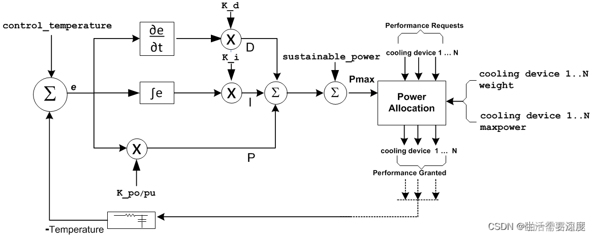
下面是一个简单的PID控制框图,负反馈的控制流程由三部分组成,分别是差分(P)、积分(I)、微分(D)组成。
P——差分项
即误差值,误差值和预定值的差异,往往直接控制于被控制量。
I——积分项
误差在时间上的积分。一个简单的比例系统(即只有差分控制的系统)会在目标值的附近来回变化,这是差分系统的性质决定的,因为系统无法消除这样的误差。积分项的作用是误差的累计,所以加上积分项可以有效消除系统的平均误差值
D——微分项
微分是误差的一阶导数,表示误差的变化率。当误差的变化率较大时,这项影响较大,系统就可以提前(或者以较快的速度)做出响应。需要说明的是在IPA中这项的系数往往是0,微分项没有参与控制
关于IPA的流程

上面的图是按ARM的bigLITTLE架构来讲的,实际的控制流程其实分成几部分:
1. 各个器件(thermal cooling device)根据自己的performance状态计算自己需求的状态。
2. IPA governor收集各个器件的状态信息,同时收集器件的温度Tdie、Tskin等。
3. IPA governor根据器件的状态信息和温度信息,同时根据前刻的状态信息,计算出此时能够赋给各个cooling device的状态信息
4. 各个cooling device得到自己的状态信息,根据governor要求调整自己的状态。
实际governor的工作
这里开始咱们对着代码来讲吧。看看代码里是怎么对温度进行收集,进而最终转化到器件的状态从而控制温度的。这里咱们主要就以CPU频率来做主要的温控器件了,其他器件同理。
主要的代码路径:
power_allocator.c
cpufreq_cooling.c
关键的结构体:
/**
* struct cpufreq_cooling_device - data for cooling device with cpufreq
* @last_load: load measured by the latest call to cpufreq_get_requested_power()
* @cpufreq_state: integer value representing the current state of cpufreq
* cooling devices.
* @max_level: maximum cooling level. One less than total number of valid
* cpufreq frequencies.
* @em: Reference on the Energy Model of the device
* @cdev: thermal_cooling_device pointer to keep track of the
* registered cooling device.
* @policy: cpufreq policy.
* @idle_time: idle time stats
* @qos_req: PM QoS contraint to apply
*
* This structure is required for keeping information of each registered
* cpufreq_cooling_device.
*/
struct cpufreq_cooling_device {
// CPU的loading,作为CPU频率换算的重要参数
u32 last_load;
// cpu的frequency
unsigned int cpufreq_state;
unsigned int max_level;
// em_perf_domain的结构体,这个是从EAS借过来的结构体,其存储了各个频点对应的power信息,可惜只有动态功耗,不过也避免了咱们再去通过电压、频率和静态功耗系数再计算一遍的困扰
struct em_perf_domain *em;
// cpufreq_policy 存储了cpu cluster相关的各种信息
struct cpufreq_policy *policy;
// SMP仅在多核状态下生效
#ifndef CONFIG_SMP
struct time_in_idle *idle_time;
#endif
// qos链表,最终生效的限频由这里下发,准备之后再写篇文章讲讲QOS(如果不鸽我就写)
struct freq_qos_request qos_req;
};
整体函数的调用链如下,总体来说还是比较清楚的
power_allocator_throttle()
allocate_power()
get_requested_power(cdev, &req_power[i])
cpufreq_get_requested_power()
get_dynamic_power(cpufreq_cdev, freq);
pid_controller(tz, control_temp, max_allocatable_power);
divvy_up_power()
power_actor_set_power(instance->cdev, instance, granted_power[i]);
首先在power_allocator_throttle 中判断是否需要进入温控,如果进入温控,则去调用allocate_power开始收集各个cooling device的performance需求,转化为power,计算状态值并得出最终能够赋给各个器件的power值,最终再下发给各个器件。
最后的代码走读放到最后一章里,我们再花一篇的篇幅来讲讲IPA的工作流程吧
函数调用与代码分析
上一节我们已经讲过IPA控制CPU发热情况的函数主要是在这两个文件中,
gov_pwer_allocator.c
cpufreq_cooling.c
调用链如下,还是比较清楚的,我们这次来拆开看看代码,看看一个thermal governor究竟是如何知道自己应该如何控制CPU频率,又是如何实现发热控制的。
函数调用链
/* 判断是否需要进入功耗的控制流程 */
power_allocator_throttle()
/* 按照各个期间的状态准备分配功耗,IPA的核心函数 */
allocate_power()
/* 各个期间通过自己的状态获取自己想要的power */
get_requested_power(cdev, &req_power[i])
/* cpu通过计算自己的freq和自己的capacity来获得自己的power */
cpufreq_get_requested_power()
/* 目前的power仅又动态功耗组成,不考虑静态功耗 */
get_dynamic_power(cpufreq_cdev, freq);
/* 进入pid的反馈控制流程,得到最终能够满足功耗分配需求的power值 */
pid_controller(tz, control_temp, max_allocatable_power);
/* 分配功耗的函数 */
divvy_up_power()
/* 各个actor将自己的功耗转换为自己的工作状态,最终下发到设备 */
power_actor_set_power(instance->cdev, instance, granted_power[i]);
power2state()
1
2
3
4
5
6
7
8
9
10
11
12
13
14
15
16
17
18
我大致画了一个流程图来给大家展示一下

其实代码上主要是由三部分组成的:
thermal_core中主要执行Thermal_governor的轮询逻辑,即去轮询thermal_zone的温度,看看是否需要进行温控措施。
gov_power_allocator中主要执行thermal_governor的总体计算过程,即统计各个部件中的状态信息,再计算这个时候可以分配的功耗,最终将实际可分配的功耗计算出来下发给设备。
各个cooling_device设备中主要执行的是跟自身设备有关的计算逻辑,主要是计算状态到功耗(state2power)和功耗到状态(power2state),我们接下来以CPU为例来聊聊整个流程。
以下的代码分析中暂时就不聊thermal_core中轮询的代码了,那个部分各个是通用的。
power_allocator_throttle()
判断当前温度是否需要进入控制流程
static int power_allocator_throttle(struct thermal_zone_device *tz, int trip)
{
/* 获取触发温度 */
ret = tz->ops->get_trip_temp(tz, params->trip_switch_on,
&switch_on_temp);
/* 当温度较低时,不控制整体的power,下发最大值*/
if (!ret && (tz->temperature < switch_on_temp)) {
tz->passive = 0;
reset_pid_controller(params);
allow_maximum_power(tz);
return 0;
}
/* 获取control temp也就是希望控制的温度,这里开始准备进入控制流程了 */
ret = tz->ops->get_trip_temp(tz, params->trip_max_desired_temperature,
&control_temp);
return allocate_power(tz, control_temp);
}
1
2
3
4
5
6
7
8
9
10
11
12
13
14
15
16
17
18
19
这里希望大家注意的是两个温度之间的区别,即trip_switch_on和control_temp,一个是开启控制的温度,一个是期望控制的目标温度,两个温度是有区别的。
比如我希望35℃时开启控制,控制可以缓慢介入,期望控制到温度为50℃时,保持设备的温度不要继续上升,这就是两个温度的意义。
接下来函数直接调用了allocate_power,这是整个IPA控制的核心函数,通过这里去进行功耗的计算、功耗的限制要求以及功耗的重新分配三个主要的流程。
alloc_power计算功耗,分配功耗
/* 这里的alloc_power是IPA整个工作流程的核心,所以代码比较长,大家耐心看 */
static int allocate_power(struct thermal_zone_device *tz,
int control_temp)
{
/* 这里的power很多,稍不注意就看混掉了 */
/* req_power: 各个actor根据自己的状态计算出的实际工作状态的值 */
/* max_power: 各个actor的最大状态能够使用的power值 */
/* granted_power:各个actor在当前状态下能够分配到的功耗值 */
/* extra_actor_power:各个actor如果没有用完granted_power,剩下来可以分配给其他actor的power*/
/* weighted_req_power: 各个cooling device有分配功耗的权重,经过权重计算后的功耗*/
/* power_range: 经过PID控制后得到的power值 */
u32 *req_power, *max_power, *granted_power, *extra_actor_power;
u32 *weighted_req_power;
u32 total_req_power, max_allocatable_power, total_weighted_req_power;
u32 total_granted_power, power_range;
/* 这里统一给他们分配了内存空间 */
req_power = kcalloc(num_actors * 5, sizeof(*req_power), GFP_KERNEL);
max_power = &req_power[num_actors];
granted_power = &req_power[2 * num_actors];
extra_actor_power = &req_power[3 * num_actors];
weighted_req_power = &req_power[4 * num_actors];
/* 这里开始遍历governor掌控下的各个cooling device,不理解cooling device
* 和governor关系的铜须可以去看第一篇文章
*/
list_for_each_entry(instance, &tz->thermal_instances, tz_node) {
int weight;
struct thermal_cooling_device *cdev = instance->cdev;
if (cdev->ops->get_requested_power(cdev, &req_power[i]))
continue;
weight = instance->weight;
weighted_req_power[i] = frac_to_int(weight * req_power[i]);
if (power_actor_get_max_power(cdev, &max_power[i]))
continue;
total_req_power += req_power[i];
max_allocatable_power += max_power[i];
total_weighted_req_power += weighted_req_power[i];
i++;
}
1
2
3
4
5
6
7
8
9
10
11
12
13
14
15
16
17
18
19
20
21
22
23
24
25
26
27
28
29
30
31
32
33
34
35
36
37
38
39
40
41
42
43
44
45
//这里的pid_controller其实就是整个PID的流程计算了,我们可以详细打开来看看这部分的代码
power_range = pid_controller(tz, control_temp, max_allocatable_power);
1
2
/**
* pid_controller() - PID controller
* @tz: thermal zone we are operating in
* @control_temp: the target temperature in millicelsius
* @max_allocatable_power: maximum allocatable power for this thermal zone
*
* This PID controller increases the available power budget so that the
* temperature of the thermal zone gets as close as possible to
* @control_temp and limits the power if it exceeds it. k_po is the
* proportional term when we are overshooting, k_pu is the
* proportional term when we are undershooting. integral_cutoff is a
* threshold below which we stop accumulating the error. The
* accumulated error is only valid if the requested power will make
* the system warmer. If the system is mostly idle, there's no point
* in accumulating positive error.
*
* Return: The power budget for the next period.
*/
static u32 pid_controller(struct thermal_zone_device *tz,
int control_temp,
u32 max_allocatable_power)
{
max_power_frac = int_to_frac(max_allocatable_power);
/* 这里是一个初始化sustainable和pid参数的过程 */
if (tz->tzp->sustainable_power) {
sustainable_power = tz->tzp->sustainable_power;
} else {
sustainable_power = estimate_sustainable_power(tz);
estimate_pid_constants(tz, sustainable_power,
params->trip_switch_on, control_temp,
true);
}
/* 计算当前的误差项,即当前温度与预期温度之间的误差 */
err = control_temp - tz->temperature;
err = int_to_frac(err);
/* 计算P值,也就是我们上一篇文章中所说的差分项,如果还没看懂,去把自动控制原理拿出来再看一遍! */
p = mul_frac(err < 0 ? tz->tzp->k_po : tz->tzp->k_pu, err);
/* 计算I值,也就是积分项 */
i = mul_frac(tz->tzp->k_i, params->err_integral);
/* 这里还有一个integral_curoff,即常数系数项,在err过小时会生效*/
if (err < int_to_frac(tz->tzp->integral_cutoff)) {
s64 i_next = i + mul_frac(tz->tzp->k_i, err);
if (abs(i_next) < max_power_frac) {
i = i_next;
params->err_integral += err;
}
}
/* 这里就是计算d
* Calculate the derivative term
*
* We do err - prev_err, so with a positive k_d, a decreasing
* error (i.e. driving closer to the line) results in less
* power being applied, slowing down the controller)
*/
d = mul_frac(tz->tzp->k_d, err - params->prev_err);
d = div_frac(d, tz->passive_delay);
params->prev_err = err;
/* p + i + d */
power_range = p + i + d;
/* sustaianble power += 上一步计算出的range */
power_range = sustainable_power + frac_to_int(power_range);
power_range = clamp(power_range, (s64)0, (s64)max_allocatable_power);
trace_thermal_power_allocator_pid(tz, frac_to_int(err),
frac_to_int(params->err_integral),
frac_to_int(p), frac_to_int(i),
frac_to_int(d), power_range);
return power_range;
}
1
2
3
4
5
6
7
8
9
10
11
12
13
14
15
16
17
18
19
20
21
22
23
24
25
26
27
28
29
30
31
32
33
34
35
36
37
38
39
40
41
42
43
44
45
46
47
48
49
50
51
52
53
54
55
56
57
58
59
60
61
62
63
64
65
66
67
68
69
70
71
72
73
74
75
76
77
78
79
这里我拿了一张ARM文档手册里的图来说明功耗是如何在请求和实际需求之间分配的。
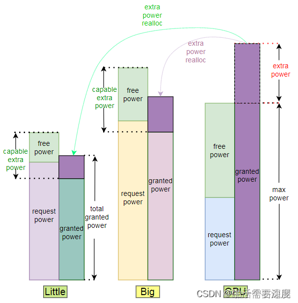
这张图描述了各个功耗分配的核心过程,你让我示意图我是画不出这么好的图的。
当需求小于给予时,大家总是能够相安无事的。矛盾总之发生在需求和给予不能相互满足的时候,即requested_power > granted_power时,我们这里可以看到各个actor的request_power,little和big的granted_power是小于其request_power的,不够分了!
这是我们把目光投到了GPU身上,大哥这个时候不用power!有多的拿来分,那可以的,于是多余的granted_power就被按需分配到了big和Little核心上。
每个actor分多少呢? 那就要看他们的需求超过了多少,需求的越多,最后拿到的也就越多。
// 接下来就是一些按需分配的操作了,具体可以参考上面这张图片。
divvy_up_power(weighted_req_power, max_power, num_actors,
total_weighted_req_power, power_range, granted_power,
extra_actor_power);
total_granted_power = 0;
i = 0;
list_for_each_entry(instance, &tz->thermal_instances, tz_node) {
if (instance->trip != trip_max_desired_temperature)
continue;
if (!cdev_is_power_actor(instance->cdev))
continue;
/* 这里其实就是把已经计算好的power分配到各个actor上,由各个actor来完成功耗
* 到状态的转换工作,与上一步刚好是一个相反的过程
*/
power_actor_set_power(instance->cdev, instance,
granted_power[i]);
total_granted_power += granted_power[i];
i++;
}
trace_thermal_power_allocator(tz, req_power, total_req_power,
granted_power, total_granted_power,
num_actors, power_range,
max_allocatable_power, tz->temperature,
control_temp - tz->temperature);
kfree(req_power);
unlock:
mutex_unlock(&tz->lock);
return ret;
}
1
2
3
4
5
6
7
8
9
10
11
12
13
14
15
16
17
18
19
20
21
22
23
24
25
26
27
28
29
30
31
32
33
34
35
36
我们最后来看看各个器件是如何做功耗和状态之间的转化的,这里我选择CPU,跟大家一起看看CPU是如何做状态到功耗之间的转化的。
其实这里主要是两个函数, 第一个是state2power,是state到power之间的转化。
/**
* cpufreq_state2power() - convert a cpu cdev state to power consumed
* @cdev: &thermal_cooling_device pointer
* @state: cooling device state to be converted
* @power: pointer in which to store the resulting power
*
* Convert cooling device state @state into power consumption in
* milliwatts assuming 100% load. Store the calculated power in
* @power.
*
* Return: 0 on success, -EINVAL if the cooling device state could not
* be converted into a frequency or other -E* if there was an error
* when calculating the static power.
*/
static int cpufreq_state2power(struct thermal_cooling_device *cdev,
unsigned long state, u32 *power)
{
unsigned int freq, num_cpus, idx;
struct cpufreq_cooling_device *cpufreq_cdev = cdev->devdata;
/* Request state should be less than max_level */
if (state > cpufreq_cdev->max_level)
return -EINVAL;
num_cpus = cpumask_weight(cpufreq_cdev->policy->cpus);
idx = cpufreq_cdev->max_level - state;
freq = cpufreq_cdev->em->table[idx].frequency;
*power = cpu_freq_to_power(cpufreq_cdev, freq) * num_cpus;
return 0;
}
static u32 cpu_freq_to_power(struct cpufreq_cooling_device *cpufreq_cdev,
u32 freq)
{
int i;
for (i = cpufreq_cdev->max_level - 1; i >= 0; i--) {
if (freq > cpufreq_cdev->em->table[i].frequency)
break;
}
return cpufreq_cdev->em->table[i + 1].power;
}
1
2
3
4
5
6
7
8
9
10
11
12
13
14
15
16
17
18
19
20
21
22
23
24
25
26
27
28
29
30
31
32
33
34
35
36
37
38
39
40
41
42
43
44
45
46
我们可以看到其实本质上就是遍历了一下cpufreq_cdev里的em->table,这个table蕴含了freq和power的对应关系,这个table是跟芯片密切相关的,往往在出厂的时候厂商就已经预制好给我们了。
其定义如下,大家一定要仔细看看这里的注释
/**
* struct em_perf_domain - Performance domain
* @table: List of performance states, in ascending order
* @nr_perf_states: Number of performance states
* @milliwatts: Flag indicating the power values are in milli-Watts
* or some other scale.
* @cpus: Cpumask covering the CPUs of the domain. It's here
* for performance reasons to avoid potential cache
* misses during energy calculations in the scheduler
* and simplifies allocating/freeing that memory region.
*
* In case of CPU device, a "performance domain" represents a group of CPUs
* whose performance is scaled together. All CPUs of a performance domain
* must have the same micro-architecture. Performance domains often have
* a 1-to-1 mapping with CPUFreq policies. In case of other devices the @cpus
* field is unused.
*/
struct em_perf_domain {
struct em_perf_state *table;
int nr_perf_states;
int milliwatts;
unsigned long cpus[];
};
1
2
3
4
5
6
7
8
9
10
11
12
13
14
15
16
17
18
19
20
21
22
23
freq2state的过程如上,其实state -> freq的过程也就是反过来了,其核心都是在这个em_perf_domain结构体中,这个结构体蕴含的是整个CPU体系中功耗和性能互相转化的核心公式!
static u32 cpu_power_to_freq(struct cpufreq_cooling_device *cpufreq_cdev,
u32 power)
{
int i;
for (i = cpufreq_cdev->max_level; i > 0; i--) {
if (power >= cpufreq_cdev->em->table[i].power)
break;
}
return cpufreq_cdev->em->table[i].frequency;
}
1
2
3
4
5
6
7
8
9
10
11
12
同样,也是查表,查到了就结束过程,返回最终的频率值。
结语
拖更了三个月,我们还是花三篇文章的篇幅把整个thermal_governor中最复杂的governor —— IPA给讲完了,实际应用中我们可能会碰到更多的问题,像是移动设备的使用延迟、功耗模型的准确度等等,内核中的解决方案非常多,值得我们好好分析,好好学习。
————————————————
版权声明:本文为博主原创文章,遵循 CC 4.0 BY-SA 版权协议,转载请附上原文出处链接和本声明。
原文链接:https://blog.csdn.net/weixin_42048864/article/details/129454228
探究CPU等设备频率、电压、功耗的关系 —— Linux中的OPP_table与energy model
上次写完IPA文章之后有小伙伴留言说自己的设备上找不到对应的em_perf_domain中频率和电压的对应关系,这里跟大家讨论CPU等设备中会存在频率、电压、功耗三者之间的关系究竟是怎么来的。
什么是OPP_table,设备的运行点
Operating Performance Points(OPP),SOC中允许一些域以较低的频率和电压运行,而其他的域运行在较高的电压和频率上。将域中每个设备支持的电压和频率的离散元组的集合称为Operating Performance Points。
其实OPP_table存在的核心意义还是为了功耗和性能之间的平衡,否则我们都把SOC直接拉到满频率跑就完事儿了,哪儿来这么多事情呢?我们在讲代码之前先来回顾一下之前的硬件知识:
性能与功耗的平衡
CPU的性能和功耗之间的关系有一个经典的公式:
为什么是V^2乘以f,这要从CPU的架构开始说起,CPU的基本组成单元其实是若干个三极管。
三极管通过控制gate的电压实现源极和漏极之间的通断,最终形成二进制0和1的表示。想象成两个水系和闸门之间的关系吧,水系沟通和阻断是通过提起和放下闸门控制的。
提起和放下这个三极管上的闸门的功耗,就是CPU实现翻转的功耗,闸门本质上是一个电容。通断控制的过程其实本质上是电容的充放电过程。公式中的P其实就是电容充放电中的功耗了。C是电容的常数项系数。V是施加在电容上的电压。开关一次的功耗是C*V^2,注意这里的单位是J(焦耳),f是频率,频率是Hz,相当于每秒调整f次,每秒消耗的能量(单位W)即这么计算出了。
这里说明清楚一点,电压和频率往往是正相关的,电压给的越高,电容能够在更短的时间内完成充放电的过程,每秒内能够翻转的次数也就越多,这就可以给到更高的运行频率了。
动态频率和电压的调整
Power是与电压和频率相关的,内核中有个非常牛逼的方案——DVFS(Dynamic Voltage Frequency Scaling)。这个方案的存在在很大程度上衡量了性能与功耗的需求。简单来说,就是芯片可以动态调节自己的电压和频率,在性能需求低的时候用低的电压和频率去跑。性能需求高的时候用高的电压和频率去跑。
这里的方案其实已经非常完备了。有控制CPU频率的DVFS方案,有控制任务在各个核心上迁移,达到最优性能功耗表现的EAS(energy aware scheduling)方案。相关的power model、energy model等也在出厂时由各大芯片厂商已经预制在了芯片中。
perf_domain的注册
在/kernel/power/energy_model.c
中可以找到这两个函数
em_register_per_domain()
em_create_pd()
这里看起来是注册了perf domain,但是freq和power的来源只是一个轻飘飘的函数:
/*
* active_power() is a driver callback which ceils 'freq' to
* lowest performance state of 'dev' above 'freq' and updates
* 'power' and 'freq' accordingly.
*/
ret = cb->active_power(&power, &freq, cpu);
函数中只是从call back中获取了power和freq然后把他们赋给了em_perf_domain中的power和freq。
具体的函数我们还是要到cb中去寻找
我们来看看cb的结构体
struct em_data_callback {
/**
* active_power() - Provide power at the next performance state of
* a device
* @power : Active power at the performance state
* (modified)
* @freq : Frequency at the performance state in kHz
* (modified)
* @dev : Device for which we do this operation (can be a CPU)
*
* active_power() must find the lowest performance state of 'dev' above
* 'freq' and update 'power' and 'freq' to the matching active power
* and frequency.
*
* In case of CPUs, the power is the one of a single CPU in the domain,
* expressed in milli-Watts or an abstract scale. It is expected to
* fit in the [0, EM_MAX_POWER] range.
*
* Return 0 on success.
*/
int (*active_power)(unsigned long *power, unsigned long *freq,
struct device *dev);
};
#define EM_DATA_CB(_active_power_cb) { .active_power = &_active_power_cb }
住市里写了很多,其实只有一个active_power的函数指针,下面定义了一个宏,这个宏非常关键。
宏对应到of.c中我们才能看到真正power和freq的对应特点。
dev_pm_opp_of_regster_em()
_get_power()
dev_pm_opp_find_freq_ceil()
dev_pm_opp_get_voltage(opp)
/* tmp = cap * mV * mV * Hz */
em_dev_register_perf_domain()
这里看起来就很清楚了,callback中调用的是_get_power函数,这个函数中调用dev_pm_opp_find_freq_ceil来确认下一个频点在哪个位置,然后通过dev_pm_opp_get_voltage来确认opp对应的电压,最终通过power = n * V ^2 * f (还记得我们在上面讲的那个cpu功耗的物理公式吗?对!就是它)计算出最终的功耗值完成频率和功耗的对应关系,最终完成这个em_perf_domain的建立。
OPP表
讲到这里其实我们只讲清楚了一个问题,em_perf_domain中的power和freq是通过OPP表来计算出来的,本质上讲我们还要讲清楚另一个问题,OPP表中的freq和voltage究竟是怎么来的呢?这个关系究竟是如何建立,系统又是如何得知的呢?我们继续往下深挖。
来看这两个函数
/**
* dev_pm_opp_get_voltage() - Gets the voltage corresponding to an opp
* @opp: opp for which voltage has to be returned for
*
* Return: voltage in micro volt corresponding to the opp, else
* return 0
*
* This is useful only for devices with single power supply.
*/
unsigned long dev_pm_opp_get_voltage(struct dev_pm_opp *opp)
{
if (IS_ERR_OR_NULL(opp)) {
pr_err("%s: Invalid parameters\n", __func__);
return 0;
}
return opp->supplies[0].u_volt;
}
EXPORT_SYMBOL_GPL(dev_pm_opp_get_voltage);
/**
* dev_pm_opp_get_freq() - Gets the frequency corresponding to an available opp
* @opp: opp for which frequency has to be returned for
*
* Return: frequency in hertz corresponding to the opp, else
* return 0
*/
unsigned long dev_pm_opp_get_freq(struct dev_pm_opp *opp)
{
if (IS_ERR_OR_NULL(opp)) {
pr_err("%s: Invalid parameters\n", __func__);
return 0;
}
return opp->rate;
}
EXPORT_SYMBOL_GPL(dev_pm_opp_get_freq);
本质上都是从dev_pm_opp这个结构体中取rate和supplies域的值,只要找清楚dev_pm_opp这个结构体的初始化过程,就能搞清楚opp中频率和电压的对应关系了。
驱动中/drivers/base/power/opp/of.c这里的这个函数其实挺有意思
/**
* dev_pm_opp_of_add_table() - Initialize opp table from device tree
* @dev: device pointer used to lookup OPP table.
*
* Register the initial OPP table with the OPP library for given device.
*
* Return:
* 0 On success OR
* Duplicate OPPs (both freq and volt are same) and opp->available
* -EEXIST Freq are same and volt are different OR
* Duplicate OPPs (both freq and volt are same) and !opp->available
* -ENOMEM Memory allocation failure
* -ENODEV when 'operating-points' property is not found or is invalid data
* in device node.
* -ENODATA when empty 'operating-points' property is found
* -EINVAL when invalid entries are found in opp-v2 table
*/
int dev_pm_opp_of_add_table(struct device *dev)
{
struct device_node *opp_np;
int ret;
/*
* OPPs have two version of bindings now. The older one is deprecated,
* try for the new binding first.
*/
opp_np = dev_pm_opp_of_get_opp_desc_node(dev);
if (!opp_np) {
/*
* Try old-deprecated bindings for backward compatibility with
* older dtbs.
*/
return _of_add_opp_table_v1(dev);
}
ret = _of_add_opp_table_v2(dev, opp_np);
of_node_put(opp_np);
return ret;
}
EXPORT_SYMBOL_GPL(dev_pm_opp_of_add_table);
这里的v1和v2是在驱动中很常见的写法,主要是为了兼容表明不同代际的驱动。这里会尝试获取opp的数目,如果无法获取,则调用V1版本的函数去初始化opp_table,如果能获取到,那么调用V2版本的函数。
其实大同小异,我们就以V1为例来看看吧
static int _of_add_opp_table_v1(struct device *dev)
{
struct opp_table *opp_table;
const struct property *prop;
const __be32 *val;
int nr, ret = 0;
prop = of_find_property(dev->of_node, "operating-points", NULL);
if (!prop)
return -ENODEV;
if (!prop->value)
return -ENODATA;
/*
* Each OPP is a set of tuples consisting of frequency and
* voltage like <freq-kHz vol-uV>.
*/
nr = prop->length / sizeof(u32);
if (nr % 2) {
dev_err(dev, "%s: Invalid OPP table\n", __func__);
return -EINVAL;
}
opp_table = dev_pm_opp_get_opp_table(dev);
if (!opp_table)
return -ENOMEM;
val = prop->value;
while (nr) {
unsigned long freq = be32_to_cpup(val++) * 1000;
unsigned long volt = be32_to_cpup(val++);
ret = _opp_add_v1(opp_table, dev, freq, volt, false);
if (ret) {
dev_err(dev, "%s: Failed to add OPP %ld (%d)\n",
__func__, freq, ret);
_dev_pm_opp_remove_table(opp_table, dev, false);
break;
}
nr -= 2;
}
dev_pm_opp_put_opp_table(opp_table);
return ret;
}
其实很简单,就是读取设备树,然后把设备树中的电压和频率映射关系建立起来的过程。
对应的设备树如下:
cpu@0 { compatible = "arm,cortex-a9";
reg = <0>;
next-level-cache = <&L2>;
operating-points = <
/* kHz uV */
792000 1100000
396000 950000
198000 850000
>;
};
总结
其实opp_table以及em_perf_domain等都着眼于建立电压、频率、功耗三者之间的关系,电压和频率之间的关系是由硬件厂商在出厂时设备树中就已经定义好了的(至于为什么这么定义,我们改天再开一篇来讲讲?),电压和频率之间严格对应,电源域的电压直接对应了SOC运行的频率。而功耗和电压之间的关系是通过一个电容充放电的物理公式来建立了联系。
文章知识点与官方知识档案匹
————————————————
版权声明:本文为博主原创文章,遵循 CC 4.0 BY-SA 版权协议,转载请附上原文出处链接和本声明。
原文链接:https://blog.csdn.net/weixin_42048864/article/details/129930066


 1061
1061


 被折叠的 条评论
为什么被折叠?
被折叠的 条评论
为什么被折叠?
 到【灌水乐园】发言


