


注:机翻,未校。
Configuring IS-IS Protocol
配置 IS-IS 协议
Sample Chapter is provided courtesy of Cisco Press.
Date: Mar 21, 2003.
This supplemental material provides an overview of Intermediate System-to-Intermediate System (IS-IS) technology and its structures and protocols, along with basic configuration examples.
本补充材料概述了中间系统到中间系统 (IS-IS) 技术及其结构和协议,以及基本配置示例。
Operation of IS-IS for CLNS/CLNP
适用于 CLNS/CLNP 的 IS-IS 操作
This section describes the operation of IS-IS. As mentioned earlier, IS-IS is used for routing CLNS/CLNP data, while Integrated IS-IS is used for routing IP. Integrated IS-IS is described in the next section.
本节介绍 IS-IS 的作。如前所述,IS-IS 用于路由 CLNS/CLNP 数据,而集成 IS-IS 用于路由 IP。集成的 IS-IS 将在下一节中介绍。
OSI Addressing
OSI 寻址
OSI network layer addressing is done through NSAP addresses that identify any system in the OSI network. These OSI addresses are often simply referred as NSAPs.
OSI 网络层寻址是通过标识 OSI 网络中的任何系统的 NSAP 地址完成的。这些 OSI 地址通常简称为 NSAP 。
NOTE 注意
A variety of NSAP formats are used for different systems, and each OSI routing protocol uses a different representation of NSAP. NSAPs usually are represented in hexadecimal format with a variable length of up to 40 hex digits. NSAPs also are used in ATM. Later in this section, you will see the format interpreted by Cisco IOS Software.
不同的系统使用各种 NSAP 格式,并且每个 OSI 路由协议使用不同的 NSAP 表示形式。NSAP 通常以十六进制格式表示,可变长度最多 40 个十六进制数字。NSAP 也用于 ATM。在本节的后面部分,您将看到 Cisco IOS 软件解释的格式。
The LSPs, hello PDUs, and other routing PDUs are OSI-format PDUs; therefore, every IS-IS router requires an OSI address even if it is routing only IP. IS-IS uses the OSI address in the LSPs to identify the router, build the topology table, and build the underlying IS-IS routing tree.
LSP、hello PDU 和其他路由 PDU 是 OSI 格式的 PDU;因此,每个 IS-IS 路由器都需要一个 OSI 地址,即使它仅路由 IP。IS-IS 使用 LSP 中的 OSI 地址来识别路由器、构建拓扑表并构建底层 IS-IS 路由树。
The NSAPs contain the following:
NSAP 包含以下内容:
-
The OSI address of the device
设备的 OSI 地址 -
The link to the higher-layer process
与更高层工艺的联系
NOTE
注意
The NSAP address can be thought of as the equivalent of a combination of IP address and upper-layer protocol in an IP header.
NSAP 地址可以被视为 IP 报头中 IP 地址和上层协议的组合。
Dijkstra’s algorithm, which is used for both IS-IS and OSPF, requires a point-to-point connection between devices. OSPF uses the router ID to represent each router for this connection, while IS-IS uses the NET (a subset of the NSAP discussed in the following section).
Dijkstra 算法用于 IS-IS 和 OSPF,要求设备之间建立点对点连接。OSPF 使用路由器 ID 来表示此连接的每个路由器,而 IS-IS 使用 NET(下一节将讨论的 NSAP 的子集)。
NSAP Address Structure
NSAP 地址结构
Cisco routers can route CLNS data that uses addressing conforming to the ISO 10589 standard. The NSAP structure is illustrated in [Figure S-6].
Cisco 路由器可以路由使用符合 ISO 10589 标准的寻址的 CLNS 数据。NSAP 结构如图 S-6 所示。
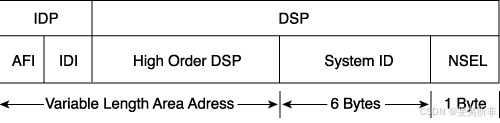
[Figure S-6] Structure of NSAP Addresses
图 S-6 NSAP 地址的结构
An OSI NSAP address can be up to 20 octets long and consists of the following parts, as shown in [Figure S-6]:
OSI NSAP 地址最长可达 20 个八位字节,由以下部分组成,如图 S-6 所示:
-
The authority and format ID (AFI) specifies the format of the address and the authority that assigned that address. The AFI is 1 byte.颁发机构和格式 ID (AFI) 指定地址的格式和分配该地址的颁发机构。AFI 为 1 字节。
-
The interdomain ID (IDI) identifies this domain. The IDI can be up to 10 bytes.
域间 ID (IDI) 标识此域。IDI 最多可为 10 字节。 -
The AFI and IDI together make up the interdomain part (IDP) of the NSAP address. This can loosely be equated to an IP classful major network.
AFI 和 IDI 共同构成了 NSAP 地址的域间部分 (IDP)。这可以大致等同于 IP 分类的主要网络。 -
The high-order domain-specific part (DSP) (HODSP) is used for subdividing the domain into areas. This can be considered loosely as the OSI equivalent of a subnet in IP.
高阶域特定部分 (DSP) (HODSP) 用于将域细分为多个区域。这可以大致视为 IP 中子网的 OSI 等效项。 -
The system ID identifies an individual OSI device (an ES or an IS). In OSI, a device has an address, just as it does in the DECnet protocol. This is different from IP, in which an interface has an address. OSI does not specify a fixed length for the system ID, but it does specify that it be consistent for all devices. Cisco IOS Software fixes the system ID as the 6 bytes preceding the 1-byte NSAP selector (NSEL).
系统 ID 标识单个 OSI 设备(ES 或 IS)。在 OSI 中,设备有一个地址,就像它在 DECnet 协议中一样。这与 IP 不同,在 IP 中,接口具有地址。OSI 没有为系统 ID 指定固定长度,但会指定所有设备 ID 的长度都是一致的。Cisco IOS 软件将系统 ID 修复为 1 字节 NSAP 选择器 (NSEL) 之前的 6 个字节。NOTE
注意A Media Access Control (MAC) address is often used for the system ID.
媒体访问控制 (MAC) 地址通常用于系统 ID。 -
The NSEL (also known as the N-selector, the service identifier or the process ID) identifies a process on the device. It is a loose equivalent of a port or socket in IP. The NSEL is 1 byte long. It is not used in routing decisions. When the NSEL is set to 00, the address identifies the device itself—its network level address. In this case, the NSAP is known as a network entity title (NET).
NSEL(也称为 N 选择器、服务标识符或进程 ID)标识设备上的进程。它是 IP 中的端口或套接字的松散等价物。NSEL 的长度为 1 字节。它不用于路由决策。当 NSEL 设置为 00 时,地址标识设备本身,即其网络级别地址。在这种情况下,NSAP 称为网络实体标题 (NET)。 -
The HODSP, system ID, and NSEL together make up the domain-specific part (DSP) of the NSAP address.
HODSP、系统 ID 和 NSEL 共同构成了 NSAP 地址的域特定部分 (DSP)。
IS-IS Versus ISO-IGRP NSAPs
IS-IS and ISO-IGRP interpret NSAPs differently, as shown in [Figure S-7]
IS-IS 和 ISO-IGRP 对 NSAP 的解释不同,如图 S-7 所示。
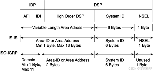
Figure S-7 How IS-IS and ISO-IGRP Interpret NSAP Addresses
图 S-7 IS-IS 和 ISO-IGRP 如何解释 NSAP 地址
IS-IS uses a two-layer architecture, joining the IDP and HODSP fields and treating them as its area address (Level 2), with the remaining system ID used for Level 1 routing. When used with IS-IS, therefore, the NSAP is divided into three parts, as shown in [Figure S-7]: 1 octet for NSEL, 6 octets for the system ID, and from 1 to 13 octets for the area address or area ID field. An NSAP has a variable length of 8 to 20 octets. It is usually longer than 8 bytes to permit some granularity in the allocation of areas.
IS-IS 采用两层架构,将 IDP 和 HODSP 字段连接起来,并将其视为其区域地址(2 级),其余系统 ID 用于 1 级路由。因此,当与 IS-IS 一起使用时,NSAP 分为三个部分,如图 S-7 所示:NSEL 为 1 个八位字节,系统 ID 为 6 个八位字节,区域地址或区域 ID 字段为 1 到 13 个八位字节。NSAP 具有 8 到 20 个八位字节的可变长度。它通常超过 8 个字节,以允许在区域分配时具有一定的粒度。
NOTE 注意
[Figure S-7] shows field length in bytes (or octets), where the NSAP address usually is represented in hexadecimal. NSAP addresses, like ATM addresses, are 160 bits long:
图 S-7 显示了以字节(或八位字节)为单位的字段长度,其中 NSAP 地址通常以十六进制表示。NSAP 地址(如 ATM 地址)的长度为 160 位:
ISO-IGRP routes are based on a three-level architecture: domain (using the AFI and IDI fields for Level 3), area (using the HODSP field for Level 2), and system ID (for Level 1). What IS-IS treats simply as the area ID, ISO-IGRP splits into a domain and an area. ISO-IGRP sets the 2 bytes to the left of the system ID as the area ID or area address field, allowing for a theoretical 65,535 areas in an ISO-IGRP network. Everything else (a maximum of 11 bytes) is treated as a domain ID. Therefore, the minimum length for an ISO-IGRP NSAP is 10 bytes (1-byte NSEL, 6-byte system ID, 2-byte area, and minimum 1-byte domain).ISO-IGRP 路由基于三级架构:域(使用 AFI 和 IDI 字段表示第 3 层)、区域(使用 HODSP 字段表示第 2 层)和系统 ID(表示第 1 层)。IS-IS 简单地视为区域 ID,而 ISO-IGRP 则拆分为一个域和一个区域。ISO-IGRP 将系统 ID 左侧的 2 个字节设置为区域 ID 或区域地址字段,从而在 ISO-IGRP 网络中允许理论上有 65,535 个区域。其他所有内容(最多 11 个字节)都被视为域 ID。因此,ISO-IGRP NSAP 的最小长度为 10 字节(1 字节 NSEL、6 字节系统 ID、2 字节区域和最小 1 字节域)。
ISO-IGRP sends routing information based on domain (variable length), area (length fixed by the protocol at 2 bytes), and finally system ID (fixed at 6 bytes). The NSEL is not used by ISO-IGRP.ISO-IGRP 根据域(可变长度)、区域(协议固定长度为 2 字节)和系统 ID(固定为 6 字节)发送路由信息。ISO-IGRP 不使用 NSEL。
Network Entity Title
网络实体标题
As discussed earlier, if the NSEL field is 00, the NSAP refers to the device itself—that is, it is the equivalent of the Layer 3 OSI address of that device.
如前所述,如果 NSEL 字段为 00,则 NSAP 是指设备本身,也就是说,它相当于该设备的第 3 层 OSI 地址。
This address with the NSEL set to 00 is known as the NET. The NET is used by routers to identify themselves in the LSPs. Therefore, it forms the basis for the OSI routing calculation.
此 NSEL 设置为 00 的地址称为 NET。路由器使用 NET 在 LSP 中识别自身。因此,它构成了 OSI 路由计算的基础。
NET Is NSAP with NSEL = 00
NET 为 NSAP 且 NSEL = 00
A key point is that an NSAP address in which the NSEL is set to 00 is called the NET.
一个关键点是,NSEL 设置为 00 的 NSAP 地址称为 NET。
NETs and NSAPs are specified in all hexadecimal digits and must start and end on a byte boundary.
NET 和 NSAP 以所有十六进制数字指定,并且必须在字节边界上开始和结束。
Official NSAP prefixes are required for CLNS routing. Addresses starting with the value of 49 (AFI = 49) are considered to be private addresses (analogous to RFC 1918 for IP addresses). These addresses are routed by IS-IS; however, this group of addresses should not be advertised to other CLNS networks.
CLNS 路由需要官方 NSAP 前缀。以值 49 开头的地址 (AFI = 49) 被视为私有地址(类似于 IP 地址的 RFC 1918)。这些地址由 IS-IS 路由;但是,不应将此组地址通告给其他 CLNS 网络。
Addresses starting with AFI values 39 and 47 represent the ISO data country code and ISO international code designator, respectively.
以 AFI 值 39 和 47 开头的地址分别表示 ISO 数据国家/地区代码和 ISO 国际代码指示符。
As shown in [Figure S-7] and the examples in the next section, the Cisco IOS Software IS-IS routing process interprets the NSAP address as follows (from the right, or least-significant digit, end):
如图 S-7 和下一节中的示例所示,Cisco IOS 软件 IS-IS 路由进程按如下方式解释 NSAP 地址(从右侧或最低有效数字结束):
-
The last byte is the NSEL field and must be specified as a single byte, with two hex digits, preceded by a period (.). In a NET, this N-selector field is set to (00).
最后一个字节是 NSEL 字段,必须指定为单个字节,具有两个十六进制数字,前面有一个句点 (.)。在 NET 中,此 N 选择器字段设置为 (00)。 -
The preceding 6 bytes (this length is fixed by Cisco IOS Software) are the system ID. It is customary to use either a MAC address from the router or (for Integrated IS-IS) an IP address (for example, the IP address of a loopback interface) as part of the system ID.
前面的 6 个字节(此长度由 Cisco IOS 软件固定)是系统 ID。通常使用来自路由器的 MAC 地址或(对于集成 IS-IS)IP 地址(例如,环回接口的 IP 地址)作为系统 ID 的一部分。 -
The IS-IS routing process of Cisco IOS Software treats the rest of the address as the area ID, or area address, as follows:
Cisco IOS 软件的 IS-IS 路由过程将地址的其余部分视为区域 ID 或区域地址,如下所示:-
It is 1 to 13 bytes long.
它的长度为 1 到 13 字节。 -
Using a 1-byte field for area limits the scope for area definitions. Thus, the customary area ID consists of 3 bytes, with an AFI of 1 byte and 2 additional bytes for the area ID. For example, in the address 49.0001.0000.0c12.3456.00, the AFI is 49 and the additional 2 bytes are 0001, for an effective area ID of 49.0001.
对 area 使用 1 字节字段会限制 Area 定义的范围。因此,惯用的区域 ID 由 3 个字节组成,其中 AFI 为 1 个字节,区域 ID 为 2 个附加字节。例如,在地址 49.0001.0000.0c12.3456.00 中,AFI 为 49,额外的 2 个字节为 0001,有效区域 ID 为 49.0001。 -
Cisco IOS Software attempts to summarize the area ID as much as possible. For example, if an IS-IS network is organized with major areas subdivided into minor areas, and this is reflected in the area ID assignments, then:
Cisco IOS 软件会尝试尽可能多地汇总区域 ID。例如,如果 IS-IS 网络的组织主要区域细分为次要区域,并且这反映在区域 ID 分配中,则:Between the minor areas, Cisco IOS Software will route based on the whole area ID.
在次要区域之间,Cisco IOS 软件将根据整个区域 ID 进行路由。Between the major areas, Cisco IOS Software will summarize the area ID portion up to the major area boundary.
在主要区域之间,Cisco IOS 软件将汇总区域 ID 部分,直到主要区域边界。
-
NSAP Examples
NSAP 示例
The following examples illustrate how an NSAP address is interpreted by IS-IS and ISO-IGRP.
以下示例说明了 IS-IS 和 ISO-IGRP 如何解释 NSAP 地址。
The NSAP 49.0001.aaaa.bbbb.cccc.00 consists of the following:NSAP 49.0001.aaaa.bbbb.cccc.00
由以下内容组成:
-
For IS-IS:
- Area = 49.0001
- System ID = aaaa.bbbb.cccc
-
For ISO-IGRP:
- Domain = 49
- Area = 0001
- System ID = aaaa.bbbb.cccc
- N-selector = ignored by ISO-IGRPN
The NSAP 39.0f01.0002.0000.0c00.1111.00 consists of the following:
NSAP 39.0f01.0002.0000.0c00.1111.00 由以下部分组成:
-
For IS-IS:
- Area = 39.0f01.0002
- System ID = 0000.0c00.1111
- N-selector = 00
-
For ISO-IGRP:
- Domain = 39.0f01
- Area = 0002
- System ID = 0000.0c00.1111
- N-selector = ignored by ISO-IGRPN
Identifying Systems in IS-IS
识别 IS-IS 中的系统
In IS-IS, the area ID is associated with the IS-IS routing process; a router can be a member of only one Level 2 area. Recall from earlier in the chapter that a router can belong to only one area. The area ID or area address uniquely identifies the routing area, and the system ID identifies each node.
在 IS-IS 中,区域 ID 与 IS-IS 路由进程相关联;路由器只能是一个 2 级区域的成员。回想一下本章前面的内容,路由器只能属于一个区域。区域 ID 或区域地址唯一标识路由区域,系统 ID 标识每个节点。
Restrictions on Areas and System IDs
区域和系统 ID 的限制
Restrictions on areas and system IDs are as follows:区域和系统 ID 的限制如下:
- All routers in an area must use the same area address. Indeed, the shared area address actually defines the area.
- 一个区域中的所有路由器必须使用相同的区域地址。事实上,共享区域地址实际上定义了区域。
- An ES might be adjacent to a Level 1 router only if they both share a common area address. In other words, ESs recognize only ISs (and ESs on the same subnetwork) that share the same area address.
- 只有当 ES 共享一个公共区域地址时,它们才可能与级别 1 路由器相邻。换句话说,ES 只识别共享同一区域地址的 IS(和同一子网上的 ES)。
- Area routing (Level 1) is based on system IDs. Therefore, each device (ES and IS) must have a unique system ID within the area, and all system IDs must be the same length. Cisco mandates a 6-byte system ID.
- 区域路由(级别 1)基于系统 ID。因此,每个设备(ES 和 IS)在该区域内必须具有唯一的系统 ID,并且所有系统 ID 的长度必须相同。Cisco 强制要求 6 字节的系统 ID。
- All Level 2 ISs come to know about all other ISs in the Level 2 backbone. Therefore, they, too, must have unique system IDs within the area.
- 所有 2 级 IS 都了解 2 级主干中的所有其他 IS。因此,它们在区域内也必须具有唯一的系统 ID。
System IDs
系统 ID
The system ID must be unique inside an area. As noted earlier, it is customary to use either a MAC address from the router or (particularly for Integrated IS-IS) to code the IP address (for example, of a loopback interface) into the system ID.
系统 ID 在一个区域内必须是唯一的。如前所述,通常使用来自路由器的 MAC 地址或(特别是对于集成 IS-IS)将 IP 地址(例如,环回接口的 IP 地址)编码为系统 ID。
It is generally recommended that the system IDs remain unique across the domain; that, way there can never be a conflict at Level 1 or Level 2 if a device is moved into a different area, for example.
通常建议系统 ID 在整个域中保持唯一;这样,例如,如果设备移动到不同的区域,则永远不会在 Level 1 或 Level 2 发生冲突。
All the system IDs in a domain must be of equal length. This is an OSI directive; Cisco enforces this by fixing the length of the system ID at 6 bytes in all cases.
域中的所有系统 ID 的长度必须相等。这是 OSI 指令;Cisco 在所有情况下都将系统 ID 的长度固定为 6 字节来强制执行此作。
Subnetwork Point of Attachment and Circuits
子网连接点和电路
Two other terms used in IS-IS are subnetwork point of attachment (SNPA) and circuit.
IS-IS 中使用的其他两个术语是子网连接点 (SNPA) 和电路。
An SNPA is the point at which subnetwork services are provided. This is similar to the Layer 2 address corresponding to the Layer 3 (NET or NSAP) address. The SNPA is usually taken from the following:
SNPA 是提供子网服务的点。这类似于与第 3 层(NET 或 NSAP)地址对应的第 2 层地址。SNPA 通常取自以下内容:
-
The MAC address on a LAN interface.
LAN 接口上的 MAC 地址。 -
The virtual circuit ID for X.25 or ATM.
X.25 或 ATM 的虚拟电路 ID。 -
The data-link connection identifier (DLCI) for Frame Relay.
帧中继的数据链路连接标识符 (DLCI)。 -
For High-Level Data Link Control (HDLC) interfaces, the SNPA is simply HDLC.
对于高级数据链路控制 (HDLC) 接口,SNPA 简称为 HDLC。
A link is the path between two neighbor ISs and is defined as being “up” when communication is possible between the two neighbors’ SNPAs.
链路是两个相邻方 IS 之间的路径,当两个相邻方的 SNPA 之间可以通信时,链路被定义为“启动”。
A circuit is an interface; interfaces are uniquely identified by a Circuit ID. The router assigns a one octet Circuit ID to each interface on the router, as follows:
电路是一个接口;接口由电路 ID 唯一标识。路由器为路由器上的每个接口分配一个八位字节电路 ID,如下所示:
-
In the case of point-to-point interfaces, this is the sole identifier for the circuit—for example, 03.
对于点对点接口,这是电路的唯一标识符,例如 03。 -
In the case of LAN interfaces (and other broadcast multi-access interfaces), this circuit ID is tagged to the end of the system ID of the DIS to form a 7-byte LAN ID. An example is 1921.6811.1001.03, where 03 is the circuit ID.
对于 LAN 接口(和其他广播多路访问接口),此电路 ID 被标记到 DIS 的系统 ID 的末尾,以形成一个 7 字节的 LAN ID。例如,1921.6811.1001.03,其中 03 是电路 ID。
Example of NET Addresses in IS-IS Network
IS-IS 网络中的 NET 地址示例
[Figure S-8] shows examples of the NETs for routers in an IS-IS domain. Observe the following in [Figure S-8]:
图 S-8 显示了 IS-IS 域中路由器的 NET 示例。在图 S-8 中观察以下内容:
-
The 6-byte system IDs are unique across the network.
6 字节的系统 ID 在网络中是唯一的。 -
The 3-byte area IDs are common to areas and distinct between areas.
3 字节区域 ID 对于区域是通用的,并且在区域之间是不同的。 -
The 1-byte N-selectors are set to 00, indicating that these are NETs.
1 字节的 N 选择器设置为 00,表示这些是 NET。
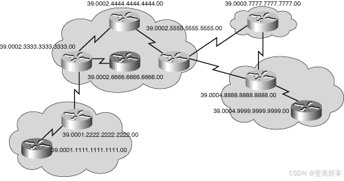
Figure S-8 NSAP Addresses in an IS-IS Network
图 S-8 IS-IS 网络中的 NSAP 地址
IS-IS PDUs
The OSI stack defines a unit of data as a protocol data unit (PDU). A frame therefore is regarded by OSI as a data-link PDU, and a packet (or datagram, in the IP world) is regarded as a network PDU.
OSI 堆栈将数据单元定义为协议数据单元 (PDU)。因此,OSI 将帧视为数据链路 PDU,而数据包(或 IP 世界中的数据报)被视为网络 PDU。
Three types of PDUs (with 802.2 Logical Link Control encapsulation) are shown in [Figure S-9]. As the figure shows, the IS-IS and ES-IS PDUs are encapsulated directly in a data-link PDU (there is no CLNP header and no IP header), while true CLNP (data) packets contain a full CLNP header between the data-link header and any higher-layer CLNS information.
图 S-9 显示了三种类型的 PDU(具有 802.2 逻辑链路控制封装)。如图所示,IS-IS 和 ES-IS PDU 直接封装在数据链路 PDU 中(没有 CLNP 报头,也没有 IP 报头),而真正的 CLNP(数据)数据包在数据链路报头和任何更高层的 CLNS 信息之间包含完整的 CLNP 报头。
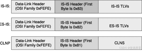
Figure S-9 OSI Protocol Data Units
图 S-9 OSI 协议数据单元
IS-IS and ES-IS PDUs contain multiple sets of variable-length fields, depending on the function of the PDU. Each field contains a type code, a length, and then the appropriate values—hence the abbreviation TLV, for Type, Length, Value fields—as shown in [Figure S-9].
IS-IS 和 ES-IS PDU 包含多组可变长度字段,具体取决于 PDU 的功能。每个字段都包含一个类型代码、一个长度,然后是相应的值,因此缩写为 TLV,用于类型、长度、值字段,如图 S-9 所示。
Four general types of packets exist, and each type can be Level 1 or Level 2:存在四种常规类型的数据包,每种类型可以是 1 级或 2 级:
- LSP—Used to distribute link-state informationLSP — 用于分发链路状态信息
- Hello PDU (ESH, ISH, IS-IS Hello [IIH])—Used to establish and maintain adjacenciesHello PDU (ESH, ISH, IS-IS Hello [IIH]) — 用于建立和维护邻接关系
- Partial sequence number PDU (PSNP)—Used to acknowledge and request link-state information部分序列号 PDU (PSNP) — 用于确认和请求链路状态信息
- Complete sequence number PDU (CSNP)—Used to distribute a router’s complete link-state database完整序列号 PDU (CSNP) — 用于分发路由器的完整链路状态数据库
LSPs and hello PDUs are detailed in the following sections; the use of PSNP and CSNP is described in the section, "Link-State Database Synchronization."以下部分详细介绍了 LSP 和 hello PDU;PSNP 和 CSNP 的使用在“链路状态数据库同步”一节中介绍。
Link State Packets
链路状态数据包
This section describes the IS-IS LSPs.本节介绍 IS-IS LSP。
Network Representation
网络表示
In OSI, there are two main types of physical links:在 OSI 中,物理链路主要有两种类型:
- Broadcast—Multiaccess media types that support addresses referring to groups of attached systems and are typically LANs.广播 — 支持引用所连接系统组的地址的多路访问媒体类型,通常是 LAN。
- Nonbroadcast—Media types that must address ESs individually and that are typically WAN links. These include point-to-point links, multipoint links, and dynamically established links.非广播 — 必须单独寻址 ES 且通常是 WAN 链路的媒体类型。这些链接包括点对点链接、多点链接和动态建立的链接。
Consequently, IS-IS supports only two media representations for its link states:因此,IS-IS 的链路状态仅支持两种媒体表示:
-
Broadcast for LANs
LAN 广播 -
Point-to-point for all other media
所有其他媒体的点对点NOTE 注意
IS-IS has no concept of an NBMA network. It is recommended that point-to-point links (for example, subinterfaces) be used instead of NBMA networks such as native ATM, Frame Relay, or X.25.
IS-IS 没有 NBMA 网络的概念。建议使用点对点链路(例如子接口)而不是 NBMA 网络,例如本地 ATM、帧中继或 X.25。
LSP Contents
LSP 内容
In IS-IS, a router describes itself with an LSP. The router’s LSP contains the following:
在 IS-IS 中,路由器使用 LSP 描述自身。路由器的 LSP 包含以下内容:
-
An LSP header, describing these items:
一个 LSP 标头,描述以下项目:-
The PDU type and length
PDU 类型和长度 -
The LSP ID and sequence number
LSP ID 和序列号 -
The remaining lifetime for this LSP (used to age out LSPs)
此 LSP 的剩余生命周期(用于使 LSP 老化)
-
-
Type Length Value (TLV) variable-length fields:
类型长度值 (TLV) 可变长度字段:-
The router’s neighbor ISs (used to build the map of the network)
路由器的邻居 IS(用于构建网络映射) -
The router’s neighbor ESs
路由器的邻居 ES -
Authentication information (used to secure routing updates)
身份验证信息(用于保护路由更新) -
Attached IP subnets (optional for Integrated IS-IS)
附加的 IP 子网(对于集成 IS-IS 是可选的)
-
The LSP sequence numbers enable receiving routers to ensure that they use only the latest LSPs in their route calculations, thus avoiding duplicate LSPs being entered in the topology tables.
LSP 序列号使接收路由器能够确保在其路由计算中仅使用最新的 LSP,从而避免在拓扑表中输入重复的 LSP。
When a router reloads, the sequence number is set initially to 1. The router might then receive its own old LSPs back from its neighbors (which has the last good sequence number before the router reloaded). It records this number and reissues its own LSPs with the next-highest sequence number.
当路由器重新加载时,序列号最初设置为 1。然后,路由器可能会从其邻居那里收到自己的旧 LSP(在路由器重新加载之前具有最后一个良好的序列号)。它会记录此编号,并使用下一个最高序列号重新颁发自己的 LSP。
The Remaining Lifetime field in the LSP is used by the LSP aging process to ensure that outdated and invalid LSPs are removed from the topology table after a suitable period. The LSP remaining lifetime counts down from 1200 seconds (20 minutes) to 0.
LSP 老化过程使用 LSP 中的 Remaining Lifetime 字段,以确保在适当的时间段后从拓扑表中删除过时和无效的 LSP。LSP 剩余生命周期从 1200 秒(20 分钟)到 0。
NOTE 注意
IS-IS uses an LSP refresh interval of 15 minutes, as specified by ISO 10589. Each IS-IS router that originates an LSP is responsible for updating its entries using this timer. The Remaining Lifetime timer is how long an LSP is kept as valid in an IS-IS LSP database.IS-IS 使用 ISO 10589 规定的 15 分钟的 LSP 刷新间隔。发起 LSP 的每个 IS-IS 路由器都负责使用此计时器更新其条目。剩余生命周期计时器是 LSP 在 IS-IS LSP 数据库中保持有效的时间。
LAN Representation
LAN 表示
Dijkstra’s algorithm, used for IS-IS, requires a virtual router (pseudonode) for broadcast media to build a weighted directed graph of the shortest paths from a single source vertex to all other vertices.用于 IS-IS 的 Dijkstra 算法需要一个用于广播媒体的虚拟路由器(伪节点)来构建从单个源顶点到所有其他顶点的最短路径的加权有向图。
For this reason, the DIS is elected to generate an LSP representing a virtual router connecting all attached routers to a star-shape topology. The DIS is shown in [Figure S-10]. The decision process for the election of the DIS is based first on the router with the highest configured priority and second on the router with the highest MAC address.
因此,选择 DIS 来生成一个 LSP,该 LSP 表示将所有连接的路由器连接到星形拓扑的虚拟路由器。DIS 如图 S-10 所示。选择 DIS 的决策过程首先基于配置优先级最高的路由器,其次基于具有最高 MAC 地址的路由器。
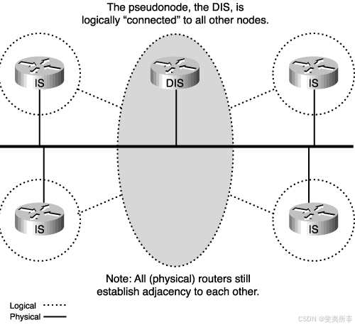
Figure S-10 IS-IS Designated Intermediate System Is Elected to Represent the LAN
图 S-10 IS-IS 指定中间系统被选为代表 LAN
In IS-IS, all routers on the LAN establish adjacencies with all other routers and with the DIS. Thus, if the DIS fails, another router can take over immediately with little or no impact on the topology of the network.
在 IS-IS 中,LAN 上的所有路由器都与所有其他路由器和 DIS 建立邻接关系。因此,如果 DIS 发生故障,另一台路由器可以立即接管,对网络拓扑的影响很小或没有影响。
This is different from OSPF behavior. In OSPF, once the designated router (DR) and a backup DR (BDR) are elected, the other routers on the LAN establish adjacencies only with the DR and the BDR (the BDR is elected, and in the case of DR failure, is then promoted to the DR).
这与 OSPF 行为不同。在 OSPF 中,一旦选择了指定路由器 (DR) 和备份 DR (BDR),LAN 上的其他路由器将仅与 DR 和 BDR 建立邻接关系(BDR 被选举出来,如果 DR 失败,则升级到 DR)。
LSP Variables
LSP 变量
IS-IS LSPs include specific information about the router’s attachments. This information is included in multiple TLV fields in the main body of the LSP:
IS-IS LSP 包括有关路由器连接的特定信息。此信息包含在 LSP 主体的多个 TLV 字段中:
-
The links to neighbor routers (ISs), including the metrics of those interfaces
-
到邻居路由器 (IS) 的链路,包括这些接口的指标
-
The links to neighbor ESs到相邻 ES 的链接
NOTE 注意
If Integrated IS-IS is operational, the attached IP subnets are described as ESs, using a special TLV specified for IP information.
如果集成 IS-IS 正常运行,则连接的 IP 子网将描述为 ES,使用为 IP 信息指定的特殊 TLV。
The metrics of IS-IS links are associated with the outgoing interface toward the neighbor IS (router). Up to four metrics can be specified, as follows:
IS-IS 链路的指标与朝向邻接方 IS(路由器)的传出接口相关联。最多可以指定四个指标,如下所示:
-
Default metric (required): cost—No automatic calculation of the metric for IS-IS takes place, compared to some routing protocols that calculate the link metric automatically based on bandwidth (OSPF) or bandwidth/delay (EIGRP). Using narrow metrics (the default), an interface cost is between 1 and 63 (a 6-bit metric value). All links use the metric of 10 by default. The total cost to a destination is the sum of the costs on all outgoing interfaces along a particular path from the source to the destination, and the least-cost paths are preferred.
默认度量(必需):成本 - 与某些根据带宽 (OSPF) 或带宽/延迟 (EIGRP) 自动计算链路度量的路由协议相比,不会自动计算 IS-IS 的度量。使用窄度量(默认值),接口开销介于 1 到 63 之间(6 位度量值)。默认情况下,所有链接都使用 10 的度量。目标的总成本是从源到目标的特定路径上所有传出接口的成本之和,首选成本最低的路径。 -
Delay, expense, and error (optional)—These metrics are intended for use in type of service (ToS) routing. These could be used to calculate alternative routes referring to the DTR (delay, throughput, and reliability) bits in the IP ToS field.
延迟、费用和错误(可选)- 这些指标旨在用于服务类型 (ToS) 路由。这些可用于计算引用 IP ToS 字段中的 DTR(延迟、吞吐量和可靠性)位的替代路由。Extended Metric 扩展度量
In IS-IS, using the old-style narrow cost metric discussed previously, the total path metric is limited to 1023 (the sum of all link metrics along a path between the calculating router and any other node or prefix). This small metric value proved insufficient for large networks and provided too little granularity for new features such as traffic engineering and other applications, especially with high-bandwidth links.
在 IS-IS 中,使用前面讨论的旧式窄成本指标,总路径指标限制为 1023(计算路由器与任何其他节点或前缀之间路径上所有链路指标的总和)。事实证明,这个较小的指标值对于大型网络来说是不够的,并且对于流量工程和其他应用程序等新功能提供的粒度太少,尤其是对于高带宽链路。Cisco IOS Software addresses this issue with the support of a 24-bit metric field, the so-called wide metric. Using the new metric style, link metrics now have a maximum value of 16,777,215 (224–1) with a total path metric of 4,294,967,295 (232–1).
Cisco IOS 软件通过支持 24 位度量字段(即宽度量)来解决此问题。使用新的度量标准样式,链路度量现在的最大值为 16,777,215 (224 –1),总路径度量为 4,294,967,295 (232 –1)。Running different metric styles within one network poses a serious problem: Link-state protocols calculate loop-free routes because all routers (within one area) calculate their routing tables based on the same link-state database. This principle is violated if some routers look at old-style (narrow) and some at new-style (wider) TLVs. However, if the same interface cost is used for both the old- and new-style metrics, the SPF computes a loop-free topology.
在一个网络中运行不同的度量样式会带来一个严重的问题:链路状态协议计算无环路路由,因为所有路由器(在一个区域内)都基于相同的链路状态数据库计算其路由表。如果某些路由器查看旧式(窄)和一些路由器查看新式(较宽)TLV,则违反了此原则。但是,如果旧式和新式指标使用相同的接口成本,则 SPF 会计算无环路拓扑。
Hello Messages
Hello 消息
IS-IS uses hello PDUs to establish adjacencies with other routers (ISs) and ESs. Hello PDUs carry information about the system, its parameters and capabilities.
IS-IS 使用 hello PDU 与其他路由器 (IS) 和 ES 建立邻接关系。Hello PDU 携带有关系统、其参数和功能的信息。
IS-IS has three types of hello PDUs, as follows:
IS-IS 有三种类型的 hello PDU,如下所示:
- ESH, sent by an ES to an IS
ESH 发送给 IS - ISH, sent by an IS to an ES
ISH,由 IS 发送到 ES - IIH, used between two ISs
IIH,用于两个 IS 之间
The three types of hello PDUs are shown in [Figure S-11].
三种类型的 hello PDU 如图 S-11 所示。
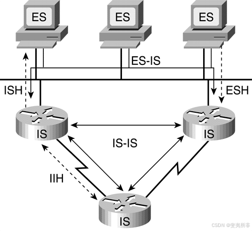
Figure S-11 Three Types of IS-IS Hello PDUs
图 S-11 三种类型的 IS-IS HELLO PDU
IS-IS Communication
IS-IS 通信
ISs use IIHs to establish and maintain their neighbor relationships. When an adjacency is established, the ISs exchange link-state information using LSPs.
IS 使用 IIH 来建立和维护其邻居关系。建立邻接关系后,IS 使用 LSP 交换链路状态信息。
ISs also send out ISHs. ESs listen for these ISHs and randomly pick an IS (the one that sent the first ISH they hear) to forward all their packets to. Hence, OSI ESs require no configuration to forward packets to the rest of the network.
IS 也会发出 ISH。ES 侦听这些 ISH 并随机选择一个 IS(发送他们听到的第一个 ISH 的 IS)以将其所有数据包转发到。因此,OSI ES 不需要配置即可将数据包转发到网络的其余部分。
ISs (routers) listen to the ESHs and learn about all the ESs on a segment. ISs include this information in their LSPs.
IS(路由器)侦听 ESH 并了解网段上的所有 ES。IS 在其 LSP 中包含此信息。
For particular destinations, ISs might send redirect (RD) messages to ESs to provide them with an optimal route off the segment. This process is similar to IP Redirect.
对于特定目标,IS 可能会向 ES 发送重定向 (RD) 消息,以便它们从网段出发获得最佳路由。此过程类似于 IP 重定向。
Adjacencies
邻接关系
Separate adjacencies are established for Level 1 and Level 2. If two neighboring routers in the same area run both Level 1 and Level 2, they establish two adjacencies, one for each level. The Level 1 and Level 2 adjacencies are stored in separate Level 1 and Level 2 adjacency tables.
为 Level 1 和 Level 2 建立了单独的邻接关系。如果同一区域中的两个相邻路由器同时运行级别 1 和级别 2,则它们会建立两个邻接关系,每个级别一个。1 级和 2 级邻接关系存储在单独的 1 级和 2 级邻接表中。
On LANs, the two adjacencies are established with specific Layer 1 and Layer 2 IIH PDUs. Routers on a LAN establish adjacencies with all other routers on the LAN and send LSPs to all routers on the LAN (unlike OSPF, in which routers establish adjacencies only with the designated router).
在 LAN 上,这两个邻接关系与特定的第 1 层和第 2 层 IIH PDU 建立。LAN 上的路由器与 LAN 上的所有其他路由器建立邻接关系,并将 LSP 发送到 LAN 上的所有路由器(与 OSPF 不同,在 OSPF 中,路由器仅与指定路由器建立邻接关系)。
On point-to-point links, there is a common IIH format, part of which specifies whether the hello relates to Level 1, Level 2, or both.
在点对点链路上,有一种常见的 IIH 格式,其中一部分指定 hello 是与级别 1 和/或级别 2 相关。
By default, hello PDUs are sent every 10 seconds; the timeout to declare a neighbor down (that is, missing three hello packets) is 30 seconds. These timers are adjustable. (The commands to adjust the timers are not discussed in this book.)
默认情况下,hello PDU 每 10 秒发送一次;声明邻居关闭(即丢失三个 hello 数据包)的超时为 30 秒。这些计时器是可调节的。
LAN Adjacencies
LAN 邻接
IIH PDUs announce the area ID. Separate IIH packets announce the Level 1 and Level 2 neighbors. Adjacencies are established based on the area address announced in the incoming IIHs and the type of the router.
IIH PDU 宣布区域 ID。单独的 IIH 数据包宣布 1 级和 2 级邻居。邻接关系是根据传入 IIH 中公布的区域地址和路由器的类型建立的。
For example, in [Figure S-12], routers from two different areas are connected to the same LAN. On this LAN, the following is true:
例如,在图 S-12 中,来自两个不同区域的路由器连接到同一个 LAN。在此 LAN 上,以下情况为 true:
-
The routers from one area accept Level 1 IIH PDUs only from their own area and, therefore, establish adjacencies only with their own area routers.
来自一个区域的路由器仅接受来自其自身区域的 1 级 IIH PDU,因此,仅与自己的区域路由器建立邻接关系。 -
The routers from a second area similarly accept Level 1 IIH PDUs only from their own area.
来自第二个区域的路由器同样仅接受来自其自身区域的 1 级 IIH PDU。 -
The Level 2 routers (or the Level 2 process within any Level 1–2 router) accept only Level 2 IIH PDUs and establish only Level 2 adjacencies.
2 级路由器(或任何 1–2 级路由器中的第 2 级进程)仅接受第 2 级 IIH PDU,并且仅建立第 2 级邻接。
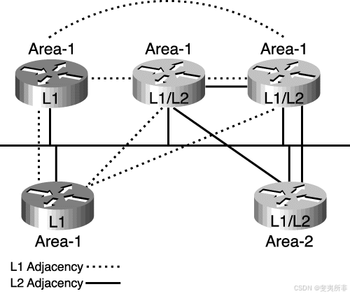
Figure S-12 IS-IS Adjacencies Are Based on Area Address and Type of Router
图 S-12 IS-IS 邻接关系基于区域地址和路由器类型
WAN Adjacencies
WAN 邻接
On point-to-point links (that is, on a WAN), the IIH PDUs are common to both Level 1 and Level 2 but announce the level type and the area ID in the hellos. This is illustrated in [Figure S-13].
在点对点链路(即 WAN 上)上,IIH PDU 对于级别 1 和级别 2 都是通用的,但在 hello 中通告级别类型和区域 ID。如图 S-13 所示。
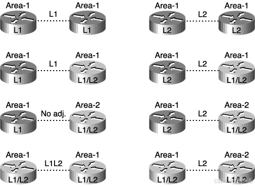
Figure S-13 On a WAN, Area Address and Router Type Are Announced in a Common IIH PDU
图 S-13 在 WAN 上,区域地址和路由器类型在公共 IIH PDU 中公布
As shown in [Figure S-13] the following is true:
如图 S-13 所示,情况如下:
-
Level 1 routers in the same area (which includes links between Level 1–only and Level 1–2 routers) exchange IIH PDUs specifying Level 1 and establish a Level 1 adjacency.
同一区域中的 1 级路由器(包括仅 1 级路由器和 1-2 级路由器之间的链路)交换指定 1 级的 IIH PDU 并建立 1 级邻接。 -
Level 2 routers (in the same area or between areas, and including links between Level 2–only and Level 1–2 routers) exchange IIH PDUs specifying Level 2 and establish a Level 2 adjacency.
2 级路由器(在同一区域或区域之间,包括仅 2 级路由器和 1-2 级路由器之间的链路)交换指定 2 级的 IIH PDU 并建立 2 级邻接。 -
Two Level 1–2 routers in the same area establish both Level 1 and Level 2 adjacencies, and maintain these with a common IIH PDU specifying both the Level 1 and Level 2 information.
同一区域中的两个 1-2 级路由器同时建立 1 级和 2 级邻接关系,并使用指定 1 级和2 级信息的公共 IIH PDU 来维护这些邻接关系。 -
Two Level 1–2 routers in different areas establish only a Level 2 adjacency.
位于不同区域的两台 1-2 级路由器仅建立 2 级邻接关系。 -
Two Level 1 routers that might be physically connected but are not in the same area (including a Level 1–only to a Level 1–2 router in a different Level 1 area) exchange Level 1 IIH PDUs but ignore these because the area IDs do not match. Therefore, they do not establish adjacency.
两个可能已物理连接但不在同一区域的 1 级路由器(包括仅连接到不同 1 级区域中的 1-2 级路由器)交换 1 级 IIH PDU,但由于区域 ID 不匹配而忽略这些 PDU。因此,它们不会建立邻接关系。
Level 2 Adjacencies
2 级邻接关系
[Figure S-14] shows examples of the following:
图 S-14 显示了以下示例:
-
Level 1–only routers establishing Level 1 adjacencies
仅 1 级路由器建立 1 级邻接 -
Level 2 routers establishing only Level 2 adjacencies (between areas)
仅建立 2 级邻接关系的 2 级路由器(区域之间) -
Level 1–2 routers establishing both Level 1 and Level 2 adjacencies with their Level 1–2 neighbors in the same area
与同一区域中的 1-2 级邻居建立 1-2 级邻接关系的 1-2 级路由器
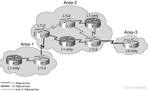
Figure S-14 Level 2 Adjacencies Must Be Continuous
图 S-14 第 2 级邻接必须连续
NOTE 注意
In OSPF, there is a backbone area; here there is a backbone path. The path of connected Level 2 routers is called the backbone. All individual areas and the backbone must be contiguous. Level 2 adjacency exists independent of the area and must be contiguous. In the example in [Figure S-14], the backbone is maintained by routers B, C, D, G, and H. A backbone is a set of contiguous Level 1–2 and Level 2 routers.
在 OSPF 中,有一个主干区域;这里有一个 backbone path 。连接的 2 级路由器的路径称为主干。所有单个区域和主干必须是连续的。2 级邻接关系独立于区域存在,并且必须是连续的。在图 S-14 的示例中,主干由路由器 B、C、D、G 和 H 维护。主干是一组连续的 1-2 级和 2 级路由器。
Link-State Database Synchronization
链路状态数据库同步
IS-IS link-state database synchronization is accomplished using special PDUs: PSNPs and CSNPs. These special PDUs bear the generic name of sequence number PDUs (SNPs),
IS-IS 链路状态数据库同步使用特殊 PDU 完成:PSNP 和 CSNP。这些特殊 PDU 带有序列号 PDU (SNP) 的通用名称,
SNPs (PSNPs and CSNPs) ensure that LSPs are sent reliably. SNPs contain LSP descriptors—not the actual, detailed LSP information, but headers describing the LSPs.
SNP(PSNP 和 CSNP)确保可靠地发送 LSP。SNP 包含 LSP 描述符 — 不是实际的详细 LSP 信息,而是描述 LSP 的标头。
PSNPs usually contain only one LSP descriptor block. They are used as follows:
PSNP 通常只包含一个 LSP 描述符块。它们的使用方式如下:
-
To acknowledge receipt of an LSP
确认收到 LSP -
To request a complete LSP for an entry missing in the originating router’s topology database
要为发起路由器的拓扑数据库中缺少的条目请求完整的 LSP
CSNPs are a list of the LSPs held by a router.
CSNP 是路由器持有的 LSP 列表。
CSNPs are sent periodically on LANs. Receiving routers can compare the list of LSPs in the CSNP with their link-state database and request (with a PSNP) any missing LSPs.
CSNP 在 LAN 上定期发送。接收路由器可以将 CSNP 中的 LSP 列表与其链路状态数据库进行比较,并请求(使用 PSNP)任何缺失的 LSP。
CSNPs are sent on point-to-point links when the link comes active. In Cisco IOS Software, periodic CSNPs can be configured on point-to-point links.
当链路处于活动状态时,CSNP 将通过点对点链路发送。在 Cisco IOS 软件中,可以在点对点链路上配置定期 CSNP。
[Figure S-15] shows an example of link-state database synchronization on a point-to-point link. In this figure, the following is true:
图 S-15 显示了点对点链路上的链路状态数据库同步示例。在此图中,情况如下:
-
A link fails.
链路失败。 -
The R2 router notices this failure and issues a new LSP noting the change.
R2 路由器注意到此故障,并发出新的 LSP 来记录此更改。 -
The R1 router receives the LSP, stores it in its topology table, and sends a PSNP back to R2 to acknowledge receipt of the LSP.
R1 路由器接收 LSP,将其存储在其拓扑表中,然后将 PSNP 发送回 R2 以确认收到 LSP。
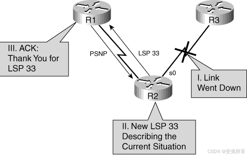
Figure S-15 Link-State Database Synchronization on a Point-to-Point Link
图 S-15 点对点链路上的链路状态数据库同步
On a LAN, the DIS periodically (every 10 seconds) sends CSNPs listing the LSPs that it holds in its link-state database. This is multicast to all IS-IS routers on the LAN.
在 LAN 上,DIS 会定期(每 10 秒)向 CSNP 发送 CSNP,列出其链路状态数据库中保存的 LSP。这是到 LAN 上所有 IS-IS 路由器的组播。
[Figure S-16] shows an example of link-state database synchronization on a LAN. In the example, the R2 router is the DIS. R2 sends a CSNP. The R1 router compares this list of LSPs with its topology table and realizes that it is missing one LSP. Therefore, it sends a PSNP to the DIS (R2) to request the missing LSP. The DIS reissues that LSP, and the R1 router acknowledges it with a PSNP (these last two steps are not shown in this figure but are similar to those in [Figure S-15].
图 S-16 显示了 LAN 上链路状态数据库同步的示例。在示例中,R2 路由器是 DIS。R2 发送 CSNP。R1 路由器将此 LSP 列表与其拓扑表进行比较,并意识到它缺少一个 LSP。因此,它会向 DIS (R2) 发送 PSNP 以请求缺少的 LSP。DIS 重新颁发该 LSP,R1 路由器使用 PSNP 确认它(最后两个步骤未显示在此图中,但与图 S-15 中的步骤类似)。
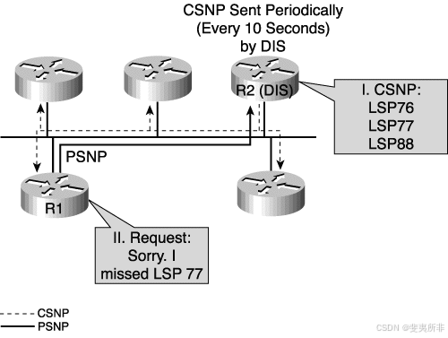
Figure S-16 Link-State Database Synchronization on a LAN
图 S-16 LAN 上的链路状态数据库同步
IP and OSI Routing with Integrated IS-IS
具有集成 IS-IS 的 IP 和 OSI 路由
Integrated IS-IS supports three types of networks:
集成的 IS-IS 支持三种类型的网络:
-
OSI only (CLNS)
仅限 OSI (CLNS) -
IP only
仅限 IP -
Dual (that is, both OSI and IP simultaneously)
双(即同时同时 OSI 和 IP)
The Integrated IS-IS LSPs can contain multiple variable-length TLV fields, with some containing OSI-specific state information and some containing IP-specific state information.
集成的 IS-IS LSP 可以包含多个可变长度 TLV 字段,其中一些包含特定于 OSI 的状态信息,一些包含特定于 IP 的状态信息。
This section explains how IP routing is accomplished in an Integrated IS-IS network and tells why CLNS addresses must be configured, even if the network is running only IP.
本节介绍如何在集成的 IS-IS 网络中完成 IP 路由,并说明为什么必须配置 CLNS 地址,即使网络仅运行 IP 也是如此。
IP Networks in Integrated IS-IS
集成 IS-IS 中的 IP 网络
Integrated IS-IS LSPs describe IP information in a similar manner to the way that IS-IS describes ESs. There are specific TLV types for IP information.
集成的 IS-IS LSP 描述 IP 信息的方式与 IS-IS 描述 ES 的方式类似。IP 信息有特定的 TLV 类型。
However, even if Integrated IS-IS is being used only for IP routing, OSI protocols are used to form the neighbor relationship between routers (routers still establish ES/IS adjacencies and use IS-IS hello packets). Therefore, a NET address is required for SPF calculations (using Dijkstra’s algorithm) and Layer 2 forwarding. The NET address is used to identify the router in Integrated IS-IS.
但是,即使集成 IS-IS 仅用于 IP 路由,OSI 协议也用于在路由器之间形成邻接关系(路由器仍建立 ES/IS 邻接并使用 IS-IS hello 数据包)。因此,SPF 计算(使用 Dijkstra 算法)和第 2 层转发需要一个 NET 地址。NET 地址用于识别集成 IS-IS 中的路由器。
This section describes how the OSI routing process works in IS-IS or Integrated IS-IS.
本节介绍 OSI 路由过程在 IS-IS 或集成 IS-IS 中的工作原理。
Building the OSI Forwarding Database
构建 OSI 转发数据库
The following process is used to build the OSI forwarding database (the CLNS routing table) in a router running IS-IS or Integrated IS-IS:
以下过程用于在运行 IS-IS 或集成 IS-IS 的路由器中构建 OSI 转发数据库(CLNS 路由表):
-
The link-state database is used to calculate the Shortest Path First (SPF) tree to OSI destinations (the NETs, or OSI addresses, of the routers). The link metrics are totaled along each path to decide which is the shortest path to any given destination.
链路状态数据库用于计算到 OSI 目标(路由器的 NET 或 OSI 地址)的最短路径优先 (SPF) 树。链路指标将沿每条路径进行汇总,以确定哪条路径是到任何给定目标的最短路径。 -
Separate link-state databases exist for Level 1 and Level 2 routes. Therefore, in Level 1–2 routers, SPF is run twice (once for each level) and separate SPF trees are created for each level.
级别 1 和级别 2 路由存在单独的链路状态数据库。因此,在 1-2 级路由器中,SPF 运行两次(每个级别一次),并为每个级别创建单独的 SPF 树。 -
ES reachability is calculated with a partial route calculation (PRC) based on the previously mentioned Level 1 and Level 2 SPF trees. (There are no OSI ESs if the network is a pure IP Integrated IS-IS environment.)
ES 可达性是根据前面提到的 1 级和 2 级 SPF 树,通过部分路由计算 (PRC) 计算的。(如果网络是纯 IP 集成的 IS-IS 环境,则没有 OSI ES。 -
The best paths are inserted in the CLNS routing table (OSI forwarding database).
最佳路径将插入到 CLNS 路由表 (OSI 转发数据库) 中。
OSI Routing Process
OSI 路由流程
Routing inside a Level 1 area is based on the system ID of the destination OSI (NSAP) address.
1 级区域内的路由基于目标 OSI (NSAP) 地址的系统 ID。
Level 1–2 routers send default routes to the Level 1 routers in their area. When a Level 1 router has a packet that is destined for another area, the following rules apply:
1–2 级路由器将默认路由发送到其所在区域的 1 级路由器。当 1 级路由器具有发往另一个区域的数据包时,以下规则适用:
-
The Level 1 router routes the packet to the nearest Level 1–2 router. The Level 1 router finds the closest exit point from the area, based on the best default route to the Level 1–2 routers in its area.
1 级路由器将数据包路由到最近的 1-2 级路由器。1 级路由器根据到其区域中 1-2 级路由器的最佳默认路由,查找离该区域最近的出口点。 -
The Level 1–2 router routes the packets into the Level 2 backbone, based on the destination area ID. The packet travels across the Level 2 backbone to the destination area.
1–2 级路由器根据目标区域 ID 将数据包路由到 2 级主干网。数据包通过 2 级主干传输到目标区域。 -
When it arrives in the destination area, Level 1 routing is again used to route the packet to its final destination inside that area.
当数据包到达目标区域时,级别 1 路由再次用于将数据包路由到该区域内的最终目标。
The interface between the Level 1 world and the Level 2 world takes place on a Level 1–2 router. The Level 1–2 router behaves as if it were both a Level 1 router (routing to Level 1 destinations) and a Level 2 router (routing between areas).
1 级世界和 2 级世界之间的接口发生在 1-2 级路由器上。1–2 级路由器的行为就像它既是 1 级路由器(路由到 1 级目标)又是 2 级路由器(区域之间的路由)。
Level 2 routing is based on the area ID. If a Level 1–2 router receives a packet (from a Level 2 neighbor) destined for its own area, it routes it as for Level 1, based on the system ID.
2 级路由基于区域 ID。如果 1–2 级路由器收到发往其自身区域的数据包(来自 2 级邻居),则它会根据系统 ID 将其路由到第 1 级。
The fact that Level 1 routers see a default route only to the nearest Level 1–2 routers can lead to suboptimal routing, as shown in [Figure S-17].
事实上,第 1 级路由器只能看到到最近的第 1-2 级路由器的默认路由,这可能会导致路由不理想,如图 S-17 所示。
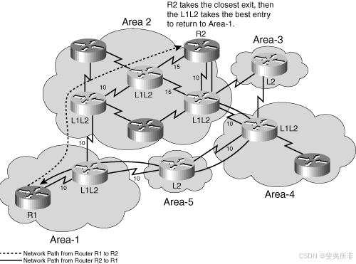
Figure S-17 Example of IS-IS Suboptimal Interarea Routing
图 S-17 IS-IS 次优区域间路由示例
In [Figure S-17], router R1 routes packets to router R2 through area 1’s Level 1–2 router. This router looks at the destination area of the packet and routes it directly into area 2. In area 2, the packets are routed as Level 1 to R2 (even though the initial next hop is another Level 1–2 router, the routing is Level 1.)
在图 S-17 中,路由器 R1 通过区域 1 的 1–2 级路由器将数据包路由到路由器 R2。此路由器查看数据包的目标区域,并将其直接路由到区域 2。在区域 2 中,数据包作为级别 1 路由到 R2(即使初始下一跃点是另一个 1-2 级路由器,路由也是级别 1。
Packets returning from R2 to R1 are routed by R2 to its nearest Level 1–2 router. This router happens to see the best route to area 1 as being through area 4 and routes the return packets by a different route than the incoming packets traveled. As can be seen in Figure S-17, the path taken is not actually the least cost from R2 to R1.
从 R2 返回到 R1 的数据包由 R2 路由到最近的 1–2 级路由器。此路由器恰好看到到区域 1 的最佳路由是通过区域 4,并通过与传输的传入数据包不同的路由路由返回数据包。从图 S-17 中可以看出,所采用的路径实际上并不是从 R2 到 R1 的最低成本。
Asymmetric routing (packets in different directions taking different paths) is not necessarily detrimental to the network.
非对称路由(不同方向的数据包采用不同的路径)不一定对网络有害。
Interconnecting IS-IS Domains
互连 IS-IS 域
An IS-IS domain is a collection of IS-IS areas and is the equivalent of an IP AS.
IS-IS 域是 IS-IS 区域的集合,相当于 IP AS。
IS-IS can support the interconnection of multiple domains. In a pure OSI (CLNS) environment, ISO-IGRP, a Cisco proprietary protocol, can be used. ISO-IGRP interprets the initial domain identifier (IDI) portion of CLNS routes and allows routing between domains. Static CLNS routes can also be used. The standard OSI Interdomain Routing Protocol (IDRP) provides the same function; however, IDRP is not supported by Cisco IOS Software.
IS-IS 可以支持多个域的互联互通。在纯 OSI (CLNS) 环境中,可以使用 Cisco 专有协议 ISO-IGRP。ISO-IGRP 解释 CLNS 路由的初始域标识符 (IDI) 部分,并允许域之间的路由。也可以使用静态 CLNS 路由。标准 OSI 域间路由协议 (IDRP) 提供相同的功能;但是,Cisco IOS 软件不支持 IDRP。
In an IP environment, an IP interdomain protocol is required. The most common of these is the Border Gateway Protocol (BGP).
在 IP 环境中,需要 IP 域间协议。其中最常见的是边界网关协议 (BGP)。
Example of OSI (CLNS) Intra-Area and Interarea Routing
OSI (CLNS) 区域内和区域间路由示例
This section presents an example of OSI (CLNS) intra-area and interarea routing, using IS-IS or Integrated IS-IS.
本节介绍使用 IS-IS 或集成 IS-IS 的 OSI (CLNS) 区域内和区域间路由示例。
# CLNS Troubleshooting Commands Used in This Example
此示例中使用的 CLNS 故障排除命令
For this example, outputs of some troubleshooting commands on a Cisco router are used to illustrate how OSI routing works. The commands used in this example are detailed in this subsection.
在本示例中,Cisco 路由器上一些故障排除命令的输出用于说明 OSI 路由的工作原理。本小节详细介绍了此示例中使用的命令。
NOTE 注意
Some of the CLNS troubleshooting commands enable you to type a CLNS name instead of an NSAP address, and some commands display a name as well as the NSAP address. This mapping of name to address can be accomplished using the clns host global configuration command; this command works similar to the ip host global configuration command and is described later, in the section, “Other Integrated IS-IS Configuration Commands.”.
某些 CLNS 故障排除命令允许您键入 CLNS 名称而不是 NSAP 地址,而某些命令显示名称和 NSAP 地址。可以使用 clns host 全局配置命令完成 name 到 address 的映射;此命令的工作方式类似于 ip host 全局配置命令,稍后将在“其他集成的 IS-IS 配置命令”部分中介绍。
Use the show isis topology [nsap] [level-1] [level-2] [l1] [l2] EXEC command to display a list of the paths to all connected routers. This command is described in Table S-1.
使用 show isis topology [ nsap ] [ level-1 ] [ level-2 ] [ l1 ] [ l2 ] EXEC 命令显示指向所有已连接路由器的路径列表。表 S-1 中描述了此命令。
Table S-1 show isis topology Command Description
表 S-1 show isis topology 命令说明
| show isis topology Command | Description |
|---|---|
| nsap NSAP | Host name or NSAP of a router. 路由器的主机名或 NSAP。 |
| level-1 | (Optional) The IS-IS link-state database for Level 1. (可选)级别 1 的 IS-IS 链路状态数据库。 |
| level-2 | (Optional) The IS-IS link-state database for Level 2. (可选)级别 2 的 IS-IS 链路状态数据库。 |
| l1 | (Optional) Abbreviation for the option level-1. (可选)选项 level-1 的缩写 。 |
| l2 | (Optional) Abbreviation for the option level-2. (可选)选项 level-2 的缩写。 |
NOTE 注意
The show isis topology command is not documented in the Cisco IOS Software Command Reference manuals; however it is shown in the Cisco IOS Software Configuration Guides, and it does work on the routers.
show isis topology 命令未记录在 Cisco IOS 软件命令参考手册中;但是,它显示在 Cisco IOS 软件配置指南中,并且它确实适用于路由器。
Use the show clns route [nsap] EXEC command to display all the CLNS destinations to which this router knows how to route packets. The nsap optional parameter is the CLNS NSAP address or host name. The output of this command displays the IS-IS Level 2 routing table, as well as static and ISO-IGRP learned prefix routes. This routing table stores IS-IS area addresses and prefix routes; destinations are sorted by category.
使用 show clns route [ nsap ] EXEC 命令显示此路由器知道如何将数据包路由到的所有 CLNS 目标。nsap 可选参数是 CLNS NSAP 地址或主机名。此命令的输出显示 IS-IS 第 2 级路由表,以及静态路由和 ISO-IGRP 学习的前缀路由。此路由表存储 IS-IS 区域地址和前缀路由;目标按类别排序。
Use the show isis route EXEC command to display the IS-IS Level 1 forwarding table for IS-IS–learned routes.
使用 show isis route EXEC 命令显示 IS-IS 学习的路由的 IS-IS 1 级转发表。
NOTE 注意
The show isis route command is documented as show isis routes in the Cisco IOS Software Command Reference manuals; however show isis route is the command that works on the routers.
show isis route 命令在 Cisco IOS 软件命令参考手册中记录为 show isis routes;但是,show isis route 是适用于路由器的命令。
This command is useful only if IS-IS is running in OSI mode. It does not display any routes if IS-IS is running only in IP mode; in this case, the command output indicates that you should use the show isis topology command instead.
仅当 IS-IS 在 OSI 模式下运行时,此命令才有用。如果 IS-IS 仅在 IP 模式下运行,则不会显示任何路由;在这种情况下,命令输出指示您应该改用 show isis topology 命令。
Use the which-route {nsap-address | clns-name} EXEC command if you want to know which next-hop router will be used or if you have multiple processes running and want to troubleshoot your configuration. This command displays the routing table in which the specified CLNS destination is found. This command is described in Table S-2.
使用 which-route { nsap-address | clns-name } EXEC 命令,如果您想知道将使用哪个下一跃点路由器,或者您有多个进程正在运行并希望对配置进行故障排除。此命令显示找到指定 CLNS 目标的路由表。表 S-2 中介绍了此命令。
Table S-2 which-route which-route Command Description
| which-route Command | Description |
|---|---|
| nsap-address | CLNS destination network address CLNS 目标网络地址 |
| clns-name | Destination host name 目标主机名 |
Use the show ip route [address [mask] [longer-prefixes]] | [protocol [process-id]] command to display all or specific portions of the IP routing table. This command is described in Table S-3.
使用 show ip route [ address [ mask ] [ longer-prefixes ]] |[ protocol [ process-id ]] 命令显示 IP 路由表的全部或特定部分。表 S-3 中介绍了此命令。
Table S-3 show ip route Command Description
表 S-3 show ip route 命令说明
| show ip route Command | Description |
|---|---|
| address | (Optional) Address about which routing information should be displayed. (可选)应显示路由信息的地址。 |
| mask | (Optional) Argument for a subnet mask. (可选)子网掩码的参数。 |
| longer-prefixes | (Optional) The address and mask pair becomes a prefix, and any routes that match that prefix are displayed. (可选)地址和掩码对将成为前缀,并显示与该前缀匹配的任何路由。 |
| protocol | (Optional) Name of a routing protocol, or the keywords connected, static, or summary. If you specify a routing protocol, use one of the following keywords: bgp, egp, eigrp, hello, igrp, isis, ospf, or rip. (可选)路由协议的名称,或者关键字 connected 、 static 或 summary 。如果指定路由协议,请使用以下关键字之一: bgp 、 egp 、 eigrp 、 hello 、 igrp 、 isis 、 ospf 或 rip 。 |
| process-id | (Optional) Number used to identify a process of the specified protocol. (可选)用于标识指定协议的进程的编号。 |
Example Network
示例网络
[Figure S-18] shows the network used in this example.
图 S-18 显示了本例中使用的网络。
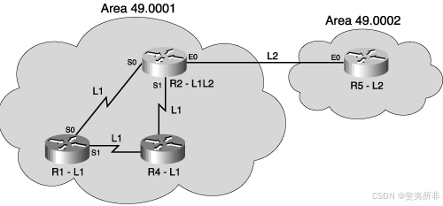
Figure S-18 Example Network for Intra-area and Inter-area Routing Discussion
图 S-18 区域内和区域间路由讨论的示例网络
Example Troubleshooting Command Output
故障排除命令输出示例
The example output of the show isis topology command shown in Example S-1 is taken from router R1, a Level 1 router, in the example in [Figure S-18].
示例 S-1 中所示的 show isis topology 命令的示例输出取自路由器 R1,即第 1 级路由器,在图 S-18 的示例中。
Example S-1 show isis topology Command Output from Router R1 in Figure S-18
示例 S-1 show isis topology 来自图 S-18 中路由器 R1 的命令输出
R1#show isis topology
IS-IS paths to level-1 routers

System Id    Metric Next-Hop  Interface SNPA
R1          - -
R2         10     R2       Se0     *HDLC*
R4         10     R4       Se1     *HDLC*
The example output of the show isis topology command shown in Example S-2 is taken from router R2, a Level 1–2 router, in the example in [Figure S-18].
示例 S-2 中所示的 show isis topology 命令的示例输出取自路由器 R2,即 1–2 级路由器,如图 S-18 所示。
Example S-2 show isis topology Command Output from Router R2 in [Figure S-18]
示例 S-2 show isis topology 图 S-18 中路由器 R2 的命令输出
R2#show isis topology
IS-IS paths to level-1 routers

System Id    Metric Next-Hop  Interface SNPA
R1          10     R1        Se0      *HDLC*
R2          --
R4          10     R4        Se1      *HDLC*
IS-IS paths to level-2 routers

System Id    Metric Next-Hop  Interface SNPA
R2          --
R5          10     R5        Et0   0010.7bb5.9e20
The show isis topology command displays the least-cost paths to the destination NETs. The fields in the outputs in Example S-1 and Example S-2 are as follows:
show isis topology 命令显示到目标 NET 的最低成本路径。示例 S-1 和示例 S-2 中输出中的字段如下:
-
The system ID shows the NET of the destination. Cisco IOS Software uses dynamic host name mapping (as defined in RFC 2763) to map this to a host name, where that host name is available to the router. A router’s host name is included in its outgoing
LSP.系统 ID 显示目标的 NET。Cisco IOS 软件使用动态主机名映射(如 RFC 2763 中所定义)将其映射到主机名,其中该主机名可供路由器使用。路由器的主机名包含在其传出 LSP 中。 -
The metric shows the sum of the metrics on the least-cost path to the destination.
该指标显示到目标的最低成本路径上的指标总和。 -
The next-hop router (an IS) is shown, along with the interface through which that next hop is reached and the SNPA of that next hop. (Recall that for a serial line, the SNPA is simply HDLC.)
将显示下一跃点路由器 (IS) 以及到达该下一跃点的接口和该下一跃点的 SNPA。(回想一下,对于串行线路,SNPA 只是 HDLC。
Example S-2 shows that separate topology databases exist for Level 1 and Level 2 in router R2, a Level 1–2 router.
示例 S-2 显示路由器 R2(级别 1–2 路由器)中的级别 1 和级别 2 存在单独的拓扑数据库。
The show clns route command displays the CLNS destinations to which this router can route packets. The example output of the show clns route command shown in Example S-3 is taken from router R1, a Level 1 router, in the example in [Figure S-18].
show clns route 命令显示此路由器可以将数据包路由到的 CLNS 目标。示例 S-3 中所示的 show clns route 命令的示例输出取自路由器 R1,即 1 级路由器,在 图 S-18 的示例中。
Example S-3 show clns route Command Output from Router R1 in [Figure S-18]
示例 S-3 show clns route 图 S-18 中路由器 R1 的命令输出
R1#show clns route

CLNS Prefix Routing Table
49.0001.0000.0000.0001.00, Local NET Entry
As Example S-3 shows, router R1 in Figure S-18 shows only its local NET entry because it is a Level 1–only router and, therefore, has no Level 2 area routes to display.
如示例 S-3 所示,图 S-18 中的路由器 R1 仅显示其本地 NET 条目,因为它是仅第 1 级路由器,因此没有要显示的第 2 级区域路由。
The show isis route command shows the Level 1 routes to IS-IS neighbors. The example output of the show isis route command shown in Example S-4 is taken from router R1 in the example in [Figure S-18]
命令 show isis route 显示到 IS-IS 邻接方的第 1 级路由。示例 S-4 中所示的 show isis route 命令的示例输出取自图 S-18 示例中的路由器 R1。
Example S-4 show isis route Command Output from Router R1 in Figure S-18
示例 S-4 show isis route 图 S-18 中路由器 R1 的命令输出
R1#show isis route
IS-IS Level-1 Routing Table - version 312

System Id Next-Hop Interface  SNPA    Metric State
R2       R2       Se0      *HDLC*  10    Up  L2-IS
R4       R4       Se1      *HDLC*  10    Up
R1       --
Default route out of area - (via 2 L2-attached ISs)
System Id Next-Hop Interface  SNPA   Metric State
          R2       Se0      *HDLC* 10    Up
As Example S-4 shows, router R1 in [Figure S-18] can see the other Level 1 routers in its area, routers R2 and R4. Level 1–2 routers appear in the Level 1 routing table (by virtue of their Level 1 connection) with a note at the end of their entry to show that they also act at Level 2. In this case, the Level 1–2 router is R2, as shown in Example S-4. The closest Level 1–2 router also appears as the default route out of the area. Again, this is router R2 in Example S-4.
如示例 S-4 所示,图 S-18 中的路由器 R1 可以看到其区域中的其他 1 级路由器,即路由器 R2 和 R4。级别 1–2 路由器显示在级别 1 路由表中(凭借其级别 1 连接),其条目末尾带有注释,表示它们也运行在级别 2。在这种情况下,级别 1-2 路由器是 R2,如示例 S-4 所示。最近的 1–2 级路由器也显示为离开该区域的默认路由。同样,这是示例 S-4 中的路由器 R2。
In the show isis route command, as in the show isis topology command, the next-hop IS, the interface over which that next hop is reached, its SNPA, and the summed metric to that destination is shown for all IS routes. In Example S-4, the state of all the neighbors is up—this indicates that the hello process has established an adjacency.
在 show isis route 命令中,与在 show isis topology 命令中一样,将显示所有 IS 路由的下一跃点 IS、到达下一跃点的接口、其 SNPA 以及到该目标的总度量。在示例 S-4 中,所有邻居的状态均为 up — 这表示 hello 进程已建立邻接关系。
For comparison, the example output of the show clns route command shown in Example S-5 is taken from router R2 in the example in [Figure S-18]. This output shows the local NET entry and also shows the Level 2 routes to its own areas and the neighbor areas.
为了进行比较,示例 S-5 中所示的 show clns route 命令的示例输出取自图 S-18 示例中的路由器 R2。此输出显示本地 NET 条目,还显示到其自身区域和相邻区域的 2 级路由。
Example S-5 show clns route Command Output from Router R2 in [Figure S-18]
示例 S-5 show clns route 图 S-18 中路由器 R2 的命令输出
R2#show clns route

CLNS Prefix Routing Table
49.0001.0000.0000.0002.00, Local NET Entry
49.0002 [110/10]
 via R5, IS-IS, Up, Ethernet0
49.0001 [110/0]
  via R2, IS-IS, Up
NOTE 注意
As displayed in Example S-5, router R2, a Level 1–2 router, regards the route to its own area (area 49.0001) as being through itself, further emphasizing that the Level 1 and Level 2 processes in a Level 1–2 router operate separately.
如示例 S-5 所示,路由器 R2(级别 1–2 路由器)将到其自身区域(区域 49.0001)的路由视为通过自身,进一步强调级别 1–2 路由器中的级别 1 和级别 2 进程是分开运行的。
The example output of the show isis route command shown in Example S-6 is taken from router R2 in [Figure S-18]. This output shows R2’s routes to its IS-IS neighbors, routers R4 and R1.
示例 S-6 中所示的 show isis route 命令的示例输出取自图 S-18 中的路由器 R2。此输出显示 R2 到其 IS-IS 邻接方、路由器 R4 和 R1 的路由。
Example S-6 show isis route Command Output from Router R2 in [Figure S-18]
示例 S-6 show isis route 图 S-18 中路由器 R2 的命令输出
R2#show isis route

IS-IS Level-1 Routing Table - version 47
System Id  Next-Hop Interface  SNPA    Metric State
R4        R4       Se1      *HDLC* 10     Up
 R1        R1       Se0      *HDLC* 10     Up
An alternative method of finding the route to a destination NET or NSAP is to use the which-route command. The example output of the which-route command shown in Example S-7 is taken Router R1 in the example in [Figure S-18].
查找到目标 NET 或 NSAP 的路由的另一种方法是使用 which-route 命令。示例 S-7 中所示的 which-route 命令的示例输出在图 S-18 示例中的路由器 R1 中采用。
Example S-7 which-route Command Output from Router R1 in [Figure S-18]
示例 S-7 图 S-18 中路由器 R1 的 which-route 命令输出
R1#which-route 49.0001.0000.0000.0002.00
Route look-up for destination 49.0001.0000.0000.0002.00
 Found route in IS-IS level-1 routing table

Adjacency entry used:
System Id Interface SNPA State Holdtime Type Protocol
0000.0000.0002 Se0   *HDLC* Up   26    L1  IS-IS
 Area Address(es): 49.0001
 Uptime: 00:09:50

R1#which-route 49.0002.0000.0000.0005.00
Route look-up for destination 49.0002.0000.0000.0005.00
 Using route to closest IS-IS level-2 router

Adjacency entry used:
System Id  Interface SNPA State Holdtime Type Protocol
0000.0000.0002 Se0   *HDLC* Up   27    L1  IS-IS
 Area Address(es): 49.0001
 Uptime: 00:09:57
In Example S-7, the which-route command is entered on the Level 1–only router, R1. The first command requests the route to router R2 (the NSAP shown in the command is R2’s NSAP). The second command requests the route to router R5. The which-route command output states whether the destination is reachable by Level 1 or by the default exit point to Level 2, and it returns information on the next hop to the destination.
在示例 S-7 中,在仅级别 1 路由器 R1 上输入 which-route 命令。第一个命令请求到路由器 R2 的路由(命令中显示的 NSAP 是 R2 的 NSAP)。第二个命令请求到路由器 R5 的路由。which-route 命令输出说明目标是否可通过级别 1 或默认出口点到达级别 2,并返回有关目标的下一跃点的信息。
For comparison, the example output of the which-route commands shown in Example S-8 is taken from router R5 in the example in [Figure S-18; R5 is a Level 2 router.
为了进行比较,示例 S-8 中所示的 which-route 命令的示例输出取自图 S-18 示例中的路由器 R5;R5 是 2 级路由器。
Example S-8 which-route Command Output from Router R5 in [Figure S-18]
图 S-18 中路由器 R5 的 S-8 which-route 命令输出示例
R5#which-route 49.0001.0000.0000.0002.00

 Found route in CLNS L2 prefix routing table

Route entry used:
i 49.0001 [110/10] via R2, Ethernet0/0
Adjacency entry used:
System Id Interface SNPA     State Hold. Type Prot
R2     Et0/0  0000.0c92.e515 Up   24  L2  IS-IS
   Area Address(es): 49.0001

R5#which-route 49.0001.0000.0000.0001.00

Found route in CLNS L2 prefix routing table

Route entry used:
i 49.0001 [110/10] via R2, Ethernet0/0
Adjacency entry used:
System Id Interface  SNPA     State Hold. Type Prot.
R2     Et0/0   0000.0c92.e515 Up   21  L2  IS-IS
   Area Address(es): 49.0001
The first command in Example S-8 requests the route to R2. The second command requests the route to R1. As shown in this example output, the which-route command output on a Level 2 router states that the route was matched by an entry from the CLNS Level 2 routing table, and it returns information on the next hop to the destination.
示例 S-8 中的第一个命令请求到 R2 的路由。第二个命令请求到 R1 的路由。如此示例输出所示,第 2 级路由器上的 which-route 命令输出指出,该路由与 CLNS 第 2 级路由表中的条目匹配,并返回有关到目的地的下一跃点的信息。
Building an IP Forwarding Table
构建 IP 转发表
So far in this section, the process and outputs have referred to the OSI part of the Integrated IS-IS process. These are the same as for pure OSI IS-IS routing.
到目前为止,在本节中,流程和输出都是指集成 IS-IS 流程的 OSI 部分。这些路由与纯 OSI IS-IS 路由相同。
However, in the IP world, when running Integrated IS-IS, IP information is included in the LSPs. IP reachability behaves in IS-IS as if it were ES information.
但是,在 IP 领域,运行集成 IS-IS 时,IP 信息包含在 LSP 中。IP 可访问性在 IS-IS 中的行为就像 ES 信息一样。
It is important to note that IP information takes no part in the calculation of the SPF tree—it is simply information about leaf connections to the tree. Therefore, updating the IP reachability is only a PRC (similar to ES reachability).
需要注意的是,IP 信息不参与 SPF 树的计算,它只是关于树的叶连接的信息。因此,更新 IP 可达性只是一个 PRC(类似于 ES 可达性)。
IP routes are generated by the PRC and offered to the IP routing table, where they are accepted based on routing table rules comparing, for example, administrative distance. When entered in the routing table, IP IS-IS routes are shown as being through Level 1 or Level 2, as appropriate.
IP 路由由 PRC 生成并提供给 IP 路由表,在路由表中,根据路由表规则(例如管理距离)接受这些路由。在路由表中输入时,IP IS-IS 路由将视情况显示为通过级别 1 或级别 2。
The separation of IP reachability from the core IS-IS network architecture gives Integrated IS-IS better scalability than OSPF. OSPF sends LSAs for individual IP subnets. If an IP subnet fails, the LSA is flooded through the network and, in all circumstances, all routers must run a full SPF calculation.
IP 可访问性与核心 IS-IS 网络架构的分离使集成 IS-IS 比 OSPF 具有更好的可扩展性。OSPF 为各个 IP 子网发送 LSA。如果 IP 子网发生故障,LSA 将通过网络泛洪,并且在所有情况下,所有路由器都必须运行完整的 SPF 计算。
In comparison, in an Integrated IS-IS network, the SPF tree is built from CLNS information. If an IP subnet fails in Integrated IS-IS, the LSP is flooded as for OSPF. However, if the failed subnet is a leaf IP subnet (that is, the loss of the subnet has not affected the underlying CLNS architecture), the SPF tree is unaffected and, therefore, only a PRC happens.
相比之下,在集成的 IS-IS 网络中,SPF 树是根据 CLNS 信息构建的。如果 IP 子网在集成 IS-IS 中发生故障,则 LSP 将与 OSPF 一样泛洪。但是,如果失败的子网是叶 IP 子网(即子网丢失不会影响底层 CLNS 架构),则 SPF 树不受影响,因此只会发生 PRC。
[Figure S-19] illustrates an IP network running Integrated IS-IS; the IP addresses shown are the addresses of the loopback 0 interface on each router. Example S-9 shows the routing table on router R2 in this example network; the routes are IS-IS routes.
图 S-19 说明了运行集成 IS-IS 的 IP 网络;显示的 IP 地址是每台路由器上环回 0 接口的地址。示例 S-9 显示了此示例网络中路由器 R2 上的路由表;这些路由是 IS-IS 路由。
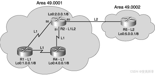
Figure S-19 An IP Network Running Integrated IS-IS
图 S-19 运行集成 IS-IS 的 IP 网络
Example S-9 show ip route Command Output from Router R2 in [Figure S-19]
示例 S-9 图 S-19 中路由器 R2 的 show ip route 命令输出
R2#show ip route
<output omitted>
i L1 1.0.0.0/8 [115/10] via 10.12.0.1, Ser0
i L1 4.0.0.0/8 [115/10] via 10.24.0.4, Ser1
i L2 5.0.0.0/8 [115/10] via 11.0.0.10, Eth0
In Example S-9, the output is interpreted as follows:在示例 S-9 中,输出解释如下:
-
The i indicates that the route was sourced from IS-IS.
i 表示路由源自 IS-IS。 -
L1 and L2 show whether the IS-IS path to these destination IP networks is by way of IS-IS Level 1 or Level 2 routing, respectively.
L1 和 L2 分别显示通往这些目标 IP 网络的 IS-IS 路径是通过 IS-IS 第 1 级还是第 2 级路由。 -
The next-hop IP addresses are the IP addresses of the corresponding next-hop IS-IS neighbor routers.
下一跃点 IP 地址是相应的下一跃点 IS-IS 邻接路由器的 IP 地址。
Basic Integrated IS-IS Router Configuration
基本集成 IS-IS 路由器配置
This section covers the commands used to configure and troubleshoot Integrated IS-IS on a Cisco router.
本节介绍用于在 Cisco 路由器上配置集成 IS-IS 并对其进行故障排除的命令。
Integrated IS-IS Configuration
集成的 IS-IS 配置
This section identifies the steps and the basic commands used to configure Integrated IS-IS on a Cisco router.
本节介绍用于在 Cisco 路由器上配置集成 IS-IS 的步骤和基本命令。
Integrated IS-IS Configuration Steps
集成的 IS-IS 配置步骤
The following steps should be taken when configuring Integrated IS-IS:
配置集成 IS-IS 时,应采取以下步骤:
| Step 1 | Define areas, prepare an addressing plan for the routers (including defining the NETs), and determine interfaces that will run Integrated IS-IS. 定义区域,为路由器准备寻址计划(包括定义 NET),并确定将运行集成 IS-IS 的接口。 |
|---|---|
| Step 2 | Enable IS-IS as an IP routing protocol on the routers, and assign a tag to the process (if required). 在路由器上启用 IS-IS 作为 IP 路由协议,并为进程分配一个标记(如果需要)。 |
| Step 3 | Configure the NETs on the routers. This identifies the routers for IS-IS. 在路由器上配置 NET。这将标识 IS-IS 的路由器。 |
| Step 4 | Enable Integrated IS-IS on the proper interfaces on the routers. Do not forget interfaces to stub IP networks, such as loopback interfaces (although there will not be any CLNS neighbors on these interfaces). 在路由器上的适当接口上启用集成 IS-IS。不要忘记末节 IP 网络的接口,例如环回接口(尽管这些接口上不会有任何 CLNS 邻居)。 |
Basic Integrated IS-IS Configuration Commands
基本集成 IS-IS 配置命令
To enable Integrated IS-IS on a router for IP routing, you need only three commands, as described in this section. Note that there are many more commands to tune the IS-IS processes, but only three are required to start Integrated IS-IS.
要在路由器上启用集成 IS-IS 以进行 IP 路由,您只需要三个命令,如本节所述。请注意,还有更多命令可用于调整 IS-IS 进程,但只需三个命令即可启动集成 IS-IS。
The router is-is [tag] global configuration command enables Integrated IS-IS on the router. The optional tag can be used to identify multiple IS-IS processes by giving a meaningful name for a routing process. If it is not specified, a null tag (0) is assumed and the process is referenced with a null tag. This name must be unique among all IP router processes for a given router.
router is-is [ tag ] 全局配置命令用来使能路由器上的集成 IS-IS。可选标记可用于通过为路由进程提供有意义的名称来识别多个 IS-IS 进程。如果未指定,则假定使用 null 标记 (0),并使用 null 标记引用进程。此名称在给定路由器的所有 IP 路由器进程中必须是唯一的。
NOTE 注意
When routing of CLNS packets is also required, use the clns routing global configuration command. (This command was on by default on the routers used for testing, but the Cisco IOS Software documentation says that it is not on by default.)
当还需要路由 CLNS 数据包时,请使用 clns routing 全局配置命令。(默认情况下,此命令在用于测试的路由器上处于打开状态,但 Cisco IOS 软件文档指出默认情况下它未打开。
After the Integrated IS-IS process is enabled, the router must be identified for IS-IS by assigning a NET to the router with the net network-entity-title router configuration command. In this command, network-entity-title is the NET that specifies the area address and the system ID for the IS-IS routing process. This argument can be either an address or a name.
启用集成 IS-IS 进程后,必须使用 net network-entity-title 路由器配置命令为路由器分配 NET,从而识别 IS-IS 的路由器。在此命令中,network-entity-title 是指定 IS-IS 路由过程的区域地址和系统 ID 的 NET。此参数可以是地址或名称。
Finally, interfaces that are to use IS-IS to distribute their IP information (and additionally might be used to establish IS-IS adjacencies) must be configured using the ip router isis [tag] interface configuration command. If there is more than one IS-IS process on the router (as specified using the router isis command), interfaces must state which IS-IS process they belong to by specifying the appropriate tag.
最后,要使用 IS-IS 分发其 IP 信息(此外还可能用于建立 IS-IS 邻接)的接口必须使用 ip router isis [ tag ] 接口配置命令进行配置。如果路由器上有多个 IS-IS 进程(使用 router isis 命令指定),则接口必须通过指定适当的标记来说明它们属于哪个 IS-IS 进程。
NOTE 注意
Configuring Integrated IS-IS to run on an interface is slightly different than configuring interfaces for most other IP routing protocols. In most other protocols, the interfaces are defined by network commands in the router configuration mode. There is no network command under the router isis command.
将集成 IS-IS 配置为在接口上运行与为大多数其他 IP 路由协议配置接口略有不同。在大多数其他协议中,接口由路由器配置模式下的 network 命令定义。router isis 命令下没有 network 命令。
When routing of CLNS packets is also required, use the clns router isis [tag] interface configuration command.
当还需要路由 CLNS 数据包时,请使用 clns router isis [ tag ] 接口配置命令。
Other Integrated IS-IS Configuration Commands
其他集成的 IS-IS 配置命令
By default, Cisco IOS Software enables both Level 1 and Level 2 operations on IS-IS routers. If a router is to operate only as an area router or only as a backbone router, this can be specified by entering the is-type {level-1 | level-1-2 | level-2-only} router configuration command. This command is described in Table S-4. To specify that the router will act only as an area (or Level 1) router, use level-1. To specify that the router will act only as a backbone (or Level 2) router, use level-2-only.
默认情况下,Cisco IOS 软件在 IS-IS 路由器上同时启用第 1 级和第 2 级作。如果路由器仅作为区域路由器或仅作为主干路由器运行,则可以通过输入 is-type { level-1 | 1-2 级 | level-2-only } 路由器配置命令。表 S-4 中介绍了此命令。要指定路由器仅充当区域(或级别 1)路由器,请使用 level-1 。要指定路由器仅充当主干(或级别 2)路由器,请使用 level-2-only 。
Table S-4 is-type Command Description
表 S-4 is-type 命令说明
| *is-type Command | Description 描述 |
|---|---|
| level-1 | Router acts as a station router. This router will learn about destinations only inside its area. For interarea routing, it depends on the closest Level 1–2 router. 路由器充当工作站路由器。此路由器将仅了解其区域内的目的地。对于区域间路由,它取决于最近的 Level 1–2 路由器。 |
| level-1-2 | Router acts as both a station router and an area router. This router will run two instances of the routing algorithm. This is the default. 路由器既充当站路由器,又充当区域路由器。此路由器将运行路由算法的两个实例。这是默认设置。 |
| level-2-only | Router acts as an area router only. This router is part of the backbone and does not talk to Level 1–only routers in its own area. 路由器仅用作区域路由器。此路由器是主干网的一部分,不与自己区域中的仅 1 级路由器通信。 |
Similarly, although the router might be a Level 1–2 router, it might be required to establish Level 1 adjacencies only over certain interfaces and Level 2 adjacencies over other interfaces. The isis circuit-type {level-1 | level-1-2 | level-2-only} interface configuration command can be used to specify either Level 1– or Level 2–only interfaces. This command is described in Table S-5. Because the default is Level 1–2, Cisco IOS Software attempts to establish both types of adjacency over the interface if this command is not specified.
同样,尽管路由器可能是 1–2 级路由器,但可能只需要在某些接口上建立 1 级邻接关系,并在其他接口上建立 2 级邻接关系。isis 电路类型 { level-1 | 1-2 级 | level-2-only } 接口配置命令可用于指定仅 1 级或 2 级接口。表 S-5 中描述了此命令。由于默认值为级别 1–2,因此如果未指定此命令,则 Cisco IOS 软件会尝试在接口上建立两种类型的邻接关系。
Table S-5 isis circuit-type Command Description
表 S-5 isis circuit-type 命令说明
| isis circuit-type Command isis circuit-type 命令 | Description 描述 |
|---|---|
| level-1 | A Level 1 adjacency might be established if there is at least one area address in common between this system and its neighbors. Level 2 adjacencies will never be established over this interface. 如果此系统与其邻居之间至少有一个公共区域地址,则可以建立 1 级邻接。永远不会通过此接口建立 2 级邻接关系。 |
| level-1-2 | A Level 1 and Level 2 adjacency is established if the neighbor is also configured as level-1-2 and there is at least one area in common. If there is no area in common, a Level 2 adjacency is established. This is the default. 如果邻居也配置为 1-2 级,并且至少有一个公共区域,则建立 1 级和 2 级邻接。如果没有公共区域,则建立 2 级邻接。这是默认设置。 |
| level-2-only | Level 2 adjacencies are established if the other routers are Level 2 or Level 1–2 routers and their interfaces are configured for Level 1–2 or Level 2. Level 1 adjacencies will never be established over this interface. 如果其他路由器是级别 2 或级别 1–2 路由器,并且其接口配置为级别 1–2 或级别 2,则建立级别 2 邻接关系。永远不会通过此接口建立 1 级邻接关系。 |
Unlike some other IP protocols, IS-IS takes no account of line speed or bandwidth when setting its link metrics. All interfaces are assigned a metric of 10 by default. To change this value, you need to use the isis metric *default-metric* {level-1 | level-2} interface configuration command. The metric can have different values for Level 1 and Level 2 over the same interface. This command is described in Table S-6.
与其他一些 IP 协议不同,IS-IS 在设置其链路指标时不考虑线路速度或带宽。默认情况下,所有接口都分配有 10 的指标。要更改此值,您需要使用 isis metric default-metric { level-1 | level-2 } 接口配置命令。同一接口上的级别 1 和级别 2 的指标可以具有不同的值。表 S-6 中描述了此命令。
Table S-6 isis metric Command Description
表 S-6 isis metric 命令说明
| isis metric Command | Description |
|---|---|
| default-metric | Specifies the metric assigned to the link and used to calculate the cost from each other router through the links in the network to other destinations. You can configure this metric for Level 1 or Level 2 routing. The range is from 0 to 63. The default value is 10. 指定分配给链路的度量,用于计算通过网络中链路从其他路由器到其他目标的成本。您可以为 1 级或 2 级路由配置此指标。范围为 0 到 63。默认值为 10。 |
| level-1 | Specifies that this metric should be used only in the SPF calculation for Level 1 (intra-area) routing. 指定此度量应仅用于级别 1(区域内)路由的 SPF 计算。 |
| level-2 | Specifies that this metric should be used only in the SPF calculation for Level 2 (interarea) routing. 指定此度量应仅用于 2 级(区域间)路由的 SPF 计算。 |
To define a name-to-NSAP mapping that can then be used with commands requiring NSAPs, use the clns host name nsap global configuration command. The assigned NSAP name is displayed, where applicable, in show and debug EXEC commands. This command is described in Table S-7.
要定义名称到 NSAP 的映射,然后可与需要 NSAP 的命令一起使用,请使用 clns host name nsap 全局配置命令。分配的 NSAP 名称显示在 show 和 debug EXEC 命令中(如果适用)。表 S-7 中描述了此命令。
Table S-7 clns host Command Description
表 S-7 clns host 命令说明
| clns host Command | Description |
|---|---|
| name | Desired name for the NSAP. The first character can be either a letter or a number, but if you use a number, the operations that you can perform are limited. NSAP 的所需名称。第一个字符可以是字母或数字,但如果使用数字,则可以执行的作将受到限制。 |
| nsap | NSAP to which that the name maps. 名称映射到的 NSAP。 |
Use the summary-address *address mask {level-1 | level-1-2 | level-2} prefix mask* router configuration command to create aggregate addresses for IS-IS or OSPF. The no summary-address command restores the default. This command is described in Table S-8.
使用 summary-address address mask {level-1 | level-1-2 | level-2} prefix mask
路由器配置命令为 IS-IS 或 OSPF 创建聚合地址。no summary-address 命令恢复默认值。表 S-8 中描述了此命令。
Table S-8 summary-address Command Description
表 S-8 summary-address 命令说明
| summary-address Command | Description |
|---|---|
| address | Summary address designated for a range of addresses. 为地址范围指定的摘要地址。 |
| mask | IP subnet mask used for the summary route. 用于汇总路由的 IP 子网掩码。 |
| level-1 | Only routes redistributed into Level 1 are summarized with the configured address/mask value. 只有重分发到级别 1 的路由才会使用配置的地址/掩码值进行汇总。 |
| level-1-2 | The summary route is applied both when redistributing routes into Level 1 and Level 2 IS-IS, and when Level 2 IS-IS–advertised Level 1 routes reachable in its area. 将路由重新分配到级别 1 和级别 2 IS-IS 时,以及当级别 2 IS-IS 通告在其区域中可访问的级别 1 路由时,都会应用汇总路由。 |
| summary-address Command | Description |
| level-2 | Routes learned by Level 1 routing are summarized into the Level 2 backbone with the configured address/mask value, and redistributed routes into Level 2 IS-IS are summarized also. 通过级别 1 路由学习的路由将汇总到具有配置地址/掩码值的级别 2 主干网中,并且还会汇总到级别 2 IS-IS 中的重新分配的路由。 |
| prefix | IP route prefix for the destination. 目标的 IP 路由前缀。 |
| mask | IP subnet mask used for the summary route. 用于汇总路由的 IP 子网掩码。 |
To configure the priority of designated routers, use the isis priority *value {level-1 | level-2}* interface configuration command. To reset the default priority, use the no form of this command. This command is described in Table S-9.
要配置指定路由器的优先级,请使用 isis priority value {level-1 | level-2} interface configuration 命令。要重置默认优先级,请使用此命令的 no 形式。表 S-9 中描述了此命令。
Table S-9 isis priority ISIS
优先级 Command Description
| Isis priority Command | Description |
|---|---|
| value | Sets the priority of a router and is a number from 0 to 127. The default value is 64. 设置路由器的优先级,是一个介于 0 到 127 之间的数字。默认值为 64。 |
| level-1 | Sets the priority for Level 1 independently. 单独设置 Level 1 的优先级。 |
| level-2 | Sets the priority for Level 2 independently. 独立设置 Level 2 的优先级。 |
Integrated IS-IS Configuration Examples
集成 IS-IS 配置示例
This section includes some example configurations of Integrated IS-IS. The first example shows the minimum commands required to run Integrated IS-IS, while the second example shows a two-area configuration.
本节包括集成 IS-IS 的一些示例配置。第一个示例显示了运行集成 IS-IS 所需的最小命令,而第二个示例显示了双区域配置。
# Basic Integrated IS-IS Configuration Example
基本集成 IS-IS 配置示例
Example S-10 shows a simple Integrated IS-IS configuration, specifying only the IS-IS process and the NET, and enabling IS-IS on the interfaces. The router with this configuration acts as an IP-only Level 1–2 router.
示例 S-10 显示了一个简单的集成 IS-IS 配置,仅指定 IS-IS 进程和 NET,并在接口上启用 IS-IS。具有此配置的路由器充当仅限 IP 的 1-2 级路由器。
Example S-10 Basic Integrated IS-IS Configuration
示例 S-10 基本集成 IS-IS 配置
interface ethernet 0
 ip address 10.1.1.1 255.255.255.0
 ip router isis
!
interface serial 0
 ip address 10.1.2.1 255.255.255.0
 ip router isis

!
router isis
  net 01.0001.0000.0000.0002.00
Two-Area Integrated IS-IS Configuration Example
两区集成 IS-IS 配置示例
This example shows how to configure a simple two-area IS-IS network, optimizing the Level 1 and Level 2 operations of the links and routers. [Figure S-20] shows the network used in this example.
此示例说明如何配置简单的两区 IS-IS 网络,从而优化链路和路由器的 1 级和 2 级作。 图 S-20 显示了本例中使用的网络。
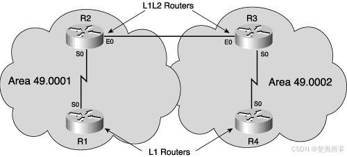
Figure S-20 Two-Area Integrated IS-IS Network
图 S-20 双区域集成 IS-IS 网络
In [Figure S-20, router R1 is in area 49.0001 with no links outside that area and, therefore, needs to operate only as a Level 1 router. The configuration for R1 is shown in Example S-11.
在图 S-20 中,路由器 R1 位于区域 49.0001 中,在该区域之外没有链路,因此只需作为级别 1 路由器运行。R1 的配置如示例 S-11 所示。
Example S-11 Configuration of Router R1 in [Figure S-20]
图 S-20 中路由器 R1 的配置 S-11 示例
hostname R1

!
interface Serial0
 ip address 192.168.120.1 255.255.255.0
 ip router isis
!
router isis
 net 49.0001.1921.6800.1005.00

is-type level-1
The is-type level-1 command under router isis in Example S-11 ensures that the router creates only a Level 1 database and takes part only in Level 1 adjacencies over its interfaces. Note that it is not necessary to also specify the isis circuit-type command on the interfaces in this case—Level 1 on the interfaces is implied by setting the IS-IS process as Level 1 only.
示例 S-11 中 router isis 下的 is-type level-1 命令可确保路由器仅创建第 1 级数据库,并且仅参与其接口上的第 1 级邻接。请注意,在这种情况下,无需在接口上指定 isis circuit-type 命令 — 通过将 IS-IS 进程设置为仅级别 1,可以隐含接口上的级别 1。
Router R2 in [Figure S-20] is a member of area 49.0001 but also connects that area with the neighboring area 49.0002. Thus, R2 is required to act as both a Level 1 and a Level 2 router. This is the default operation of the is-type command**,** so this command is not required in the router definition. The configuration of R2 is shown in Example S-12.
图 S-20 中的路由器 R2 是区域 49.0001 的成员,但也将该区域与相邻区域 49.0002 连接起来。因此,R2 需要同时充当级别 1 和级别 2 路由器。这是 is-type 命令的默认作,因此路由器定义中不需要此命令。R2 的配置如示例 S-12 所示。
Example S-12 Configuration of Router R2 in [Figure S-20]
图 S-20 中路由器 R2 的配置 S-12 示例
hostname R2!
interface Ethernet0
 ip address 192.168.220.2 255.255.255.0
 ip router isis
 isis circuit-type level-2-only
!
interface Serial0
 ip address 192.168.120.2 255.255.255.0
 ip router isis
 isis circuit-type level-1
!
router isis
 net 49.0001.1921.6800.1006.00
To optimize the operation of the interfaces to its two neighbors, router R2 in this example includes configuration to specify the type of adjacency to be established. Serial 0, the interface toward router R1 (in the same area), specifies isis circuit-type level-1, while the Ethernet 0 interface, the interface toward router R3 (in a different area, and therefore Level 2), has isis circuit-type level-2-only specified.
为了优化其两个邻接方的接口作,此示例中的路由器 R2 包括用于指定要建立的邻接类型的配置。串行 0 是指向路由器 R1(在同一区域)的接口,指定 isis 电路类型级别 1,而以太网 0 接口是指向路由器 R3 的接口(位于不同区域,因此是级别 2),指定了 isis 电路类型级别 2-only。
NOTE 注意
The interfaces on both routers R1 and R2 could also have had the isis metric command configured, to reflect the different metrics on the serial and Ethernet interfaces.
路由器 R1 和 R2 上的接口也可能配置了 isis metric 命令,以反映串行和以太网接口上的不同度量。
Troubleshooting Integrated IS-IS集成 IS-IS 故障排除
This section identifies commands that can be used to troubleshoot Integrated IS-IS on a Cisco router.
本节介绍可用于对 Cisco 路由器上的集成 IS-IS 进行故障排除的命令。
CLNS Troubleshooting Commands CLNS 故障排除命令
Troubleshooting Integrated IS-IS, even in an IP-only network, requires some investigation of CLNS data. For example, the IS-IS neighbor relationships are established over OSI, not over IP, so showing IS-IS neighbors requires using the show clns neighbors command (as described later in this section). Indeed, two ends of a CLNS adjacency can actually have IP addresses on different subnets, with no impact to the operation of IS-IS (although IP next-hop resolution could be an issue).
对集成的 IS-IS 进行故障排除,即使在仅 IP 网络中,也需要对 CLNS 数据进行一些调查。例如,IS-IS 邻居关系是通过 OSI 而不是 IP 建立的,因此显示 IS-IS 邻居需要使用 show clns neighbors 命令(如本节后面所述)。事实上,CLNS 邻接关系的两端实际上可以在不同的子网上具有 IP 地址,而不会影响 IS-IS 的运行(尽管 IP 下一跃点解析可能是一个问题)。
Some of the CLNS troubleshooting commands are shown in the context of an earlier example, in the section, “CLNS Troubleshooting Commands Used in This Example.” In this section, more CLNS show commands are described.
一些 CLNS 故障排除命令显示在前面示例的上下文中,即“此示例中使用的 CLNS 故障排除命令”部分。在本节中,将介绍更多 CLNS show 命令。
The show clns EXEC command displays general information about the CLNS network.
show clns EXEC 命令显示有关 CLNS 网络的一般信息。
The show clns protocol [domain | area-tag] EXEC command displays information for the specific IS-IS processes in the router. This command is described in Table S-10.
show clns protocol [ domain | area-tag ] EXEC 命令显示路由器中特定 IS-IS 进程的信息。表 S-10 中介绍了此命令。
Table S-10 show clns protocol 显示 CLNS 协议 Command Description
| show clns protocol Command | Description |
|---|---|
| domain | (Optional) Particular ISO IGRP routing domain (可选)特定 ISO IGRP 路由域 |
| area-tag | (Optional) Particular IS-IS area (可选)特定 IS-IS 区域 |
The show clns interface [type number] EXEC command displays CLNS-specific information about the interfaces running IS-IS. This command is described in Table S-11.
show clns interface [ type number ] EXEC 命令显示有关运行 IS-IS 的接口的 CLNS 特定信息。表 S-11 中描述了此命令。
Table S-11 show clns interface 显示 CLNS 接口 Command Description
| show clns interface Command | Description |
|---|---|
| type | (Optional) Interface type (可选)接口类型 |
| number | (Optional) Interface number (可选)接口编号 |
The show clns neighbors [type number] [detail] EXEC command is very useful because it displays the neighbor ISs—that is, the routers with which this router has IS-IS adjacencies. (ES neighbors, if there are any, are also displayed.) This command is described in Table S-12.
show clns neighbors [ type number ] [ detail ] EXEC 命令非常有用,因为它显示邻居 IS,即与此路由器具有 IS-IS 邻接关系的路由器。(如果 ES 邻居(如果有)也会显示。表 S-12 中介绍了此命令。
Table S-12 show clns neighbors 显示 CLNS 邻居 Command Description
| show clns neighbors Command | Description |
|---|---|
| type | (Optional) Interface type. (可选)接口类型。 |
| number | (Optional) Interface number. (可选)接口编号。 |
| detail | (Optional) When specified, the area addresses advertised by the neighbor in the hello messages are displayed. Otherwise, a summary display is provided. (可选)指定后,将显示邻居在 hello 消息中公布的区域地址。否则,将提供摘要显示。 |
The optional keyword detail in the show clns neighbors command displays comprehensive information about the neighbors rather than listing a summary of the neighbors, as is the case without that keyword specified. The list of neighbors can be narrowed to those neighbors across a particular interface by specifying the interface type and number parameters in the command.
show clns neighbors 命令中的可选关键字 detail 显示有关邻居的全面信息,而不是列出邻居的摘要,就像没有指定该关键字的情况一样。通过在命令中指定接口类型和编号参数,可以将邻居列表缩小到特定接口上的邻居。
To display IS-IS–related information for IS-IS router adjacencies, use the show clns is-neighbors [type number] [detail] EXEC command. Neighbor entries are sorted according to the area in which they are located. This command is described in Table S-13.
要显示 IS-IS 路由器邻接的 IS-IS 相关信息,请使用 show clns is-neighbors [ type number ] [ detail ] EXEC 命令。相邻条目根据其所在的区域进行排序。表 S-13 中介绍了此命令。
Table S-13 show clns is-neighbors Command Description
表 S-13 show clns is-neighbors 命令描述
| show clns is-neighbors Command show clns is-neighbors | Description |
|---|---|
| type | (Optional) Interface type. (可选)接口类型。 |
| number | (Optional) Interface number. (可选)接口编号。 |
| detail | (Optional) When specified, the areas associated with the intermediate systems are displayed. Otherwise, a summary display is provided. (可选)指定后,将显示与中间系统关联的区域。否则,将提供摘要显示。 |
CLNS and IS-IS Troubleshooting Commands
CLNS 和 IS-IS 故障排除命令
Further commands to troubleshoot the Integrated IS-IS network are described in this section.
本节介绍了对集成 IS-IS 网络进行故障排除的更多命令。
The show isis route EXEC command displays the IS-IS Level 1 routing table (that is, routes to all other system IDs in the area). An example output from this command is shown earlier, in the section “Example of OSI (CLNS) Intra-Area and Interarea Routing.”
show isis route EXEC 命令显示 IS-IS 第 1 级路由表(即到区域中所有其他系统 ID 的路由)。此命令的示例输出显示在前面的“OSI (CLNS) 区域内和区域间路由示例”部分中。
The show clns route [nsap] EXEC command displays the IS-IS Level 2 routing table (as well as static and ISO-IGRP–learned prefix routes). More details on this command and an example output are shown earlier, in the section, "Example of OSI (CLNS) Intra-Area and Interarea Routing.
"show clns route [ nsap ] EXEC 命令显示 IS-IS 第 2 级路由表(以及静态路由和 ISO-IGRP 获取的前缀路由)。有关此命令和示例输出的更多详细信息,请参阅前面的“OSI (CLNS) 区域内和区域间路由示例”部分。
The show isis database [level-1] [level-2] [l1] [l2] [detail] [lspid] EXEC command displays the contents of the IS-IS link-state database. This command is described in Table S-14.
show isis database [ level-1 ] [ level-2 ] [ l1 ] [ l2 ] [ detail ] [ lspid ] EXEC 命令显示 IS-IS 链路状态数据库的内容。表 S-14 中介绍了此命令。
Table S-14 show isis database Command Description
表 S-14 show isis database 命令说明
| show isis database Command | Description |
|---|---|
| level-1 | (Optional) Displays the IS-IS link-state database for Level 1. (可选)显示级别 1 的 IS-IS 链路状态数据库。 |
| level-2 | (Optional) Displays the IS-IS link-state database for Level 2. (可选)显示级别 2 的 IS-IS 链路状态数据库。 |
| l1 | (Optional) Abbreviation for the option level-1. (可选)选项 level-1 的缩写 。 |
| l2 | (Optional) Abbreviation for the option level-2. (可选)选项 level-2 的缩写。 |
| show isis database Command show isis database 命令 | Description 描述 |
| detail 细节 | (Optional) When specified, the contents of each LSP are displayed. Otherwise, a summary display is provided. (可选)指定后,将显示每个 LSP 的内容。否则,将提供摘要显示。 |
| lspid LSPID | (Optional) The link-state PDU identifier. When specified, the contents of a single LSP are displayed by its ID number. (可选)链路状态 PDU 标识符。指定后,单个 LSP 的内容将按其 ID 号显示。 |
To force IS-IS to refresh its link-state database and recalculate all routes, issue the clear isis [tag | *****] command, specifying the IS-IS process tag or ***** to clear all IS-IS entries.
要强制 IS-IS 刷新其链路状态数据库并重新计算所有路由,请发出 clear isis [ tag | * ] 命令,指定 IS-IS 进程标签,或 * 清除所有 IS-IS 条目。
NOTE 注意
The clear isis command is not documented in the Cisco IOS Software documentation, but it does work on the routers.
clear isis 命令未记录在 Cisco IOS 软件文档中,但它在路由器上确实有效。
To display how often and why the router has run a full SPF calculation, use the show isis spf-log EXEC command.
要显示路由器运行完整 SPF 计算的频率和原因,请使用 show isis spf-log EXEC 命令。
IP Troubleshooting Commands IP 故障排除命令
To troubleshoot the IP functionality of the Integrated IS-IS network, you can use standard IP show commands.
要对集成 IS-IS 网络的 IP 功能进行故障排除,可以使用标准 IP show 命令。
The show ip protocols EXEC command displays the active routing protocols, what interfaces they are active on, what networks they are routing for, and other parameters related to the routing protocols.
show ip protocols EXEC 命令显示活动路由协议、它们在哪些接口上处于活动状态、它们为哪些网络路由以及与路由协议相关的其他参数。
The show ip route [address [mask] [longer-prefixes]] | [protocol [process-id]] command displays the IP routing table. The detail for a particular route or a list of all routes in the routing table from a particular process can be specified. This command is described in detail earlier in the section, "Example of OSI (CLNS) Intra-Area and Interarea Routing.
"show ip route [ address [ mask ] [ long-prefixes ]] |[ protocol [ process-id ]]
命令显示 IP 路由表。可以指定特定路由的详细信息或来自特定进程的路由表中所有路由的列表。此命令在前面的“OSI (CLNS) 区域内和区域间路由示例”中详细介绍。
Integrated IS-IS Troubleshooting Command Output Examples
集成的 IS-IS 故障排除命令输出示例
The network used to obtain these example outputs is the same as the one used for the earlier configuration examples shown in [Figure S-20]. The network is shown again in [Figure S-21], with the IP addresses added.
用于获取这些示例输出的网络与图 S-20 中所示的早期配置示例所使用的网络相同。网络再次显示在图 S-21 中,并添加了 IP 地址。
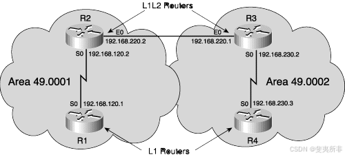
Figure S-21 Two-Area Integrated IS-IS Network with IP Addressing
图 S-21 具有 IP 寻址的两区集成 IS-IS 网络
The system IDs of the routers in [Figure S-21] are as follows:
图 S-21 中路由器的系统 ID 如下:
-
Router R1: 1921.6800.1005
-
Router R2: 1921.6800.1006
-
Router R3: 1921.6800.1007
-
Router R4: 1921.6800.1008
Example S-13 shows the show clns protocol command output from router R2 in [Figure S-21].
示例 S-13 显示了图 S-21 中路由器 R2 的 show clns protocol 命令输出。
Example S-13 show clns protocol Command Output from Router R2 in [Figure S-21]
示例 S-13 图 S-21 中路由器 R2 的 show clns protocol 命令输出
R2#show clns protocol
IS-IS Router: <Null Tag>
 System Id: 1921.6800.1006.00 IS-Type: level-1-2
 Manual area address(es):
    49.0001
 Routing for area address(es):
    49.0001
 Interfaces supported by IS-IS:
    Serial0 - IP
    Ethernet0 - IP
 Redistributing:
  static
 Distance: 110
Example S-13 shows the following:示例 S-13 显示了以下内容:
-
The Integrated IS-IS process tag (if present). Router R2 has a null tag.
集成的 IS-IS 进程标记(如果存在)。路由器 R2 具有 null 标记。 -
The system ID, level type(s), and area ID for this router. Router R2’s system ID is 1921.6800.1006.00, it is a Level 1–2 router, and it is in area 49.0001.
此路由器的系统 ID、级别类型和区域 ID。路由器 R2 的系统 ID 是 1921.6800.1006.00,它是 1–2 级路由器,位于区域 49.0001 中。 -
The interfaces using Integrated IS-IS for routing (including whether that is for IP or CLNS or both). On router R2, interfaces Serial 0 and Ethernet 0 are using Integrated IS-IS for IP routing only.
使用集成 IS-IS 进行路由的接口(包括是用于 IP 还是 CLNS,还是两者兼而有之)。在路由器 R2 上,接口 Serial 0 和 Ethernet 0 仅将集成 IS-IS 用于 IP 路由。 -
Any redistribution of other route sources. Router R2 is redistributing static routes, by default.
其他路由源的任何重新分发。默认情况下,路由器 R2 正在重新分发静态路由。 -
The administrative distance for CLNS routes. This is similar to the administrative distances used for IP routing. For IS-IS in a CLNS environment, the default administrative distance is 110, as shown for router R2 in this example. (Use the distance value [clns] router configuration command to change this default.)
CLNS 路由的管理距离。这类似于用于 IP 路由的管理距离。对于 CLNS 环境中的 IS-IS,默认管理距离为 110,如本例中的路由器 R2 所示。(使用 distance value [ clns ] router configuration 命令更改此默认值。
Example S-14 shows the show clns neighbors command output from routers R1 and R2.示例 S-14 显示了路由器 R1 和 R2 的 show clns neighbors 命令输出。
Example S-14 show clns neighbors Command Output from Routers R1 and R2 in [Figure S-21]
示例 S-14 显示图 S-21 中路由器 R1 和 R2 的 clns neighbors 命令输出
R1#show clns neighbors
System Id      Interface  SNPA         State  Holdtime Type Protocol
1921.6800.1006 Se0        *HDLC*       Up     28       L1   IS-IS
R2#show clns neighbors
System Id      Interface  SNPA         State  Holdtime Type Protocol
1921.6800.1007 Et0      0010.7b81.d6ec  Up    24       L2   IS-IS
1921.6800.1005 Se0      *HDLC*          Up    21       L1   IS-IS
Example S-14 indicates the following:示例 S-14 表示以下内容:
-
The IS-IS neighbors. Router R1 has one neighbor, router R2; Router R2 has two neighbors, routers R1 and R3.
IS-IS 邻居。路由器 R1 有一个邻接方,即路由器 R2;路由器 R2 有两个邻接方,即路由器 R1 和 R3。 -
The neighbors SNPA and state.
邻居 SNPA 和 state. -
The hold time, the number of seconds before this adjacency entry times out. It indicates the remaining time to wait for receipt of a hello before the neighbor is declared down.
保持时间,即此邻接条目超时前的秒数。它表示在声明邻居关闭之前等待收到 hello 的剩余时间。 -
The neighbors’ level and type. Router R1 sees R2 as a Level 1 router. Router R2 sees R1 as a Level 1 router and R3 as a Level 2 router.
邻居的级别和类型。路由器 R1 将 R2 视为级别 1 路由器。路由器 R2 将 R1 视为级别 1 路由器,将 R3 视为级别 2 路由器。
Example S-15 shows the show clns interface command output from router R2.示例 S-15 显示了路由器 R2 的 show clns interface 命令输出。
Example S-15 show clns interface Command Output from Router R2 in Figure S-21
示例 S-15 图 S-21 中路由器 R2 的 show clns interface 命令输出
R2#show clns interface s0
Serial0 is up, line protocol is up
 Checksums enabled, MTU 1500, Encapsulation HDLC
 ERPDUs enabled, min. interval 10 msec.
 RDPDUs enabled, min. interval 100 msec., Addr Mask enabled
 Congestion Experienced bit set at 4 packets
 CLNS fast switching enabled
 CLNS SSE switching disabled
 DEC compatibility mode OFF for this interface
 Next ESH/ISH in 21 seconds
 Routing Protocol: IS-IS
  Circuit Type: level-1
  Interface number 0x1, local circuit ID 0x100
  Level-1 Metric: 10, Priority: 64, Circuit ID: 1921.6800.1006.00
  Number of active level-1 adjacencies: 1
   Next IS-IS Hello in 7 seconds
Example S-15 indicates the following:
示例 S-15 表示以下内容:
-
That the Serial 0 interface is running IS-IS and is attempting to establish only Level 1 adjacenciesSerial 0
接口正在运行 IS-IS,并且仅尝试建立第 1 级邻接 -
The interface numbers and circuit ID for IS-IS purposes
用于 IS-IS 的接口号和电路 ID -
The metric(s) for the interface and a priority for DIS negotiation (not relevant in this case because it is a serial interface)
接口的度量和 DIS 协商的优先级(在本例中无关,因为它是串行接口) -
Information about hello timers and the number of adjacencies that have been established
有关 hello 计时器和已建立的邻接关系数量的信息
Example S-16 shows the show ip protocols command output from router R2.
示例 S-16 显示了路由器 R2 的 show ip protocols 命令输出。
Example S-16 show ip protocols Command Output from Router R2 in [Figure S-21]
示例 S-16 图 S-21 中路由器 R2 的 show ip protocols 命令输出
R2#show ip protocols
Routing Protocol is "isis"
 Sending updates every 0 seconds
 Invalid after 0 seconds, hold down 0, flushed after 0
 Outgoing update filter list for all interfaces is
 Incoming update filter list for all interfaces is
 Redistributing: isis
 Address Summarization:
  None
 Routing for Networks:
  Ethernet0
  Serial0
 Routing Information Sources:
  Gateway     Distance   Last Update
  192.168.120.1    115   00:04:53
  192.168.220.1    115   00:04:58
  Distance: (default is 115)
Example S-16 shows that Integrated IS-IS is running on router R2. It also shows the interfaces taking part in Integrated IS-IS and the sources of routing information (the neighbor routers). The default IP administrative distance for Integrated IS-IS is 115.示例 S-16 显示集成 IS-IS 正在路由器 R2 上运行。它还显示了参与集成 IS-IS 的接口和路由信息源(邻接路由器)。集成 IS-IS 的默认 IP 管理距离为 115。
Example S-17 shows the show ip route isis command output from routers R1 and R2. This command displays only the IS-IS routes from the IP routing table.示例 S-17 显示了路由器 R1 和 R2 的 show ip route isis 命令输出。此命令仅显示 IP 路由表中的 IS-IS 路由。
Example S-17 show ip route isis Command Output from Routers R1 and R2 in [Figure S-21]
示例 S-17 图 S-21 中路由器 R1 和 R2 的 show ip route isis 命令输出
R1#show ip route isis
i*L1 0.0.0.0/0 [115/10] via 192.168.120.2, Serial0
R2#show ip route isis
 i L2 192.168.230.0/24 [115/20] via 192.168.220.1, Ethernet0
The route in Example S-17 on router R1 is from Level 1, as indicated by the i L1 tag; this is a default route to router R2. The route in Example S-17 on router R2 is from Level 2, as indicated by the i L2 tag. As for all IP routes, the administrative distance and the metric are shown in square brackets, as in [115/20]. Integrated IS-IS has an IP administrative distance of 115, by default. The metric shown for each route is the IS-IS cost to the destination.
路由器 R1 上示例 S-17 中的路由来自级别 1,如 i L1 标记所示;这是到路由器 R2 的默认路由。路由器 R2 上示例 S-17 中的路由来自级别 2,如 i L2 标记所示。对于所有 IP 路由,管理距离和度量显示在方括号中,如 [115/20] 所示。默认情况下,集成 IS-IS 的 IP 管理距离为 115。为每个路由显示的指标是到达目的地的 IS-IS 成本。
NOTE 注意
There are two different administrative distances. The CLNS administrative distance, shown in the show clns protocol command, defaults to 110; the IP administrative distance for IS-IS routes, shown in the show ip route command, defaults to 115.
有两种不同的管理距离。命令中显示的 CLNS 管理距离 show clns protocol 默认为 110;命令中显示的 IS-IS 路由的 IP 管理距离(如 show ip route )默认为 115。
Example S-18 shows the show clns command output from router R2.
示例 S-18 显示了路由器 R2 的 show clns 命令输出。
Example S-18 show clns Command Output from Router R2 in [Figure S-21]
示例 S-18 图 S-21 中路由器 R2 的 show clns 命令输出
R2#show clns
Global CLNS Information:
 2 Interfaces Enabled for CLNS
 NET: 49.0001.1921.6800.1006.00
 Configuration Timer: 60, Default Holding Timer: 300, Packet Lifetime 64
 ERPDU's requested on locally generated packets
 Intermediate system operation enabled (forwarding allowed)
 IS-IS level-1-2 Router:
   Routing for Area: 49.0001
Example S-18 shows that router R2 has two interfaces enabled for CLNS and that it is a Level 1–2 router in area 49.0001.
示例 S-18 显示路由器 R2 为 CLNS 启用了两个接口,并且它是区域 49.0001 中的级别 1–2 路由器。
Example S-19 shows the show clns is-neighbors command output from routers R1 and R2.
示例 S-19 显示了路由器 R1 和 R2 的 show clns is-neighbors 命令输出。
Example S-19 show clns is-neighbors Command Output from Routers R1 and R2 in [Figure S-21]
示例 S-19 show clns is-neighbors 图 S-21 中路由器 R1 和 R2 的命令输出
R1#show clns is-neighbors
System Id      Interface  State Type Priority Circuit Id       Format
1921.6800.1006 Se0      Up   L1  0      00            Phase V
R2#show clns is-neighbors
System Id      Interface  State Type Priority Circuit Id       Format
1921.6800.1007 Et0      Up   L2  64     1921.6800.1006.0      Phase V
1921.6800.1005 Se0      Up   L1  0      00                    Phase V
As shown in Example S-19, router R1 has one IS neighbor, router R2. Router R2 has two IS neighbors, routers R1 and R3.
如示例 S-19 所示,路由器 R1 有一个 IS 邻居,即路由器 R2。路由器 R2 有两个 IS 邻接方,即路由器 R1 和 R3。
Example S-20 shows the show isis databse command output from router R2.
示例 S-20 显示了路由器 R2 的 show isis databse 命令输出。
Example S-20 show isis database Command Output from Router R2 in [Figure S-21]
示例 S-20 show isis database 图 S-21 中路由器 R2 的命令输出
R2#show isis database
IS-IS Level-1 Link State Database
LSPID              LSP Seq Num LSP Checksum LSP Holdtime   ATT/P/OL
1921.6800.1005.00-00  0x00000004   0x485B       936           0/0/0
1921.6800.1006.00-00* 0x00000005   0x2E18       1155          1/0/0
1921.6800.1006.01-00* 0x00000001   0xFC74       462           0/0/0

IS-IS Level-2 Link State Database
LSPID         LSP Seq Num LSP Checksum LSP Holdtime   ATT/P/OL
1921.6800.1006.00-00* 0x00000003  0x28FA    1180       0/0/0
1921.6800.1006.01-00* 0x00000002  0x7C36    1196       0/0/0
1921.6800.1007.00-00 0x00000003   0xF3BF     462       0/0/0
Example S-20 shows that router R2, a Level 1–2 router, has two separate databases, one for Level 1 and another for Level 2.
示例 S-20 显示路由器 R2(级别 1–2 路由器)有两个单独的数据库,一个用于级别 1,另一个用于级别 2。
Example S-21 shows the show isis spf-log command output from router R2. This command displays how often and why the router has run a full SPF calculation.
示例 S-21 显示来自路由器 R2 的 show isis spf-log 命令输出。此命令显示路由器运行完整 SPF 计算的频率和原因。
Example S-21 show isis spf-log Command Output from Router R2 in [Figure S-21]
示例 S-21 中路由器 R2 的 show isis spf-log 命令输出
R2#show isis spf-log

  Level 1 SPF log
 When  Duration Nodes Count   Last trigger LSP  Triggers
00:17:52    0   1   4 1921.6800.1006.00-00 NEWAREA NEWADJ NEWLSP TLVCONTENT
00:17:47    4   2   1 1921.6800.1005.00-00 TLVCONTENT
00:12:24    4   3   2 1921.6800.1006.01-00 NEWLSP TLVCONTENT
00:12:13    4   3   2 1921.6800.1006.00-00 ATTACHFLAG LSPHEADER
00:04:32    4   3   1            PERIODIC

  Level 2 SPF log
 When  Duration Nodes Count   Last trigger LSP  Triggers
00:17:53    0   1   1 1921.6800.1006.00-00 NEWLSP
00:12:24    4   2   3 1921.6800.1006.01-00 NEWADJ NEWLSP TLVCODE
00:12:19    4   3   1 1921.6800.1007.00-00 NEWLSP
00:04:33    8   3   1            PERIODIC
As Example S-21 shows, router R2 keeps separate logs for the Level 1 and Level 2 SPF algorithm.
如示例 S-21 所示,路由器 R2 为 1 级和 2 级 SPF 算法保留单独的日志。
via:
- Operation of IS-IS for CLNS/CLNP > Configuring IS-IS Protocol | Building Scalable Cisco Networks - Published Oct 27, 2000 by Cisco Press
https://www.ciscopress.com/articles/article.asp?p=31319&seqNum=2
https://www.ciscopress.com/articles/article.asp?p=31319&seqNum=3
https://www.ciscopress.com/articles/article.asp?p=31319&seqNum=4


 被折叠的 条评论
为什么被折叠?
被折叠的 条评论
为什么被折叠?
 到【灌水乐园】发言


