


注:本文为 “ Vlan 间通信” 相关文章合辑。
英文引文,机翻未校。
图片清晰度限于原文图源状态。
未整理去重。
How to Establish Communications between VLANs?
如何在 VLAN 之间建立通信?
Posted on November 20, 2015 by RouterSwitch Tech
In this article we will discuss how to establish communications between VLANs, as well as how to configure the networks.
在本文中,我们将讨论如何在 VLAN 之间建立通信,以及如何配置网络。
Notes: More about the virtual LANs, Physical LANs and briefly reviewed VLAN configuration options you can read the articles shared here:
First of all, let’s take a look at the 3 methods of permitting traffic to flow between VLANs
首先,我们来看看允许流量在 VLAN 之间流动的 3 种方法
Communications Options:
通信选项:
- Configure a router and connect a single interface to a switch per VLAN configured.
配置路由器并将单个接口连接到每个配置的 VLAN 的交换机。 - Configure a router to use IEEE 802.1Q and connect to a switch via a trunk.
将路由器配置为使用 IEEE 802.1Q 并通过中继连接到交换机。 - Configure (and possibly purchase) a Layer 3–capable switch.
配置(并可能购买)支持第 3 层的交换机。
Option 1 is really only practical for companies that are very small, don’t require a large number of ports, and don’t anticipate growing quickly. This option’s only opportunity for growth is by using an expensive router port (per VLAN). Options 2 and 3 are appropriate for the majority of networks deployed over the last 15 years or so.
选项 1 实际上仅适用于非常小、不需要大量端口且预计不会快速增长的公司。此选项的唯一增长机会是使用昂贵的路由器端口(每个 VLAN)。选项 2 和 3 适用于过去 15 年左右部署的大多数网络。

This example assumes that four different VLANs on SW1 need to be connected together. Using this option, a new interface is required per device per VLAN, all of which need to communicate, so four different interfaces are linked from the Layer 2 switch (SW1) to the router (R1). If the company wants to add another VLAN sometime in the future, it will need a new interface to link the new VLAN from SW1 to R1. This network design is inherently wasteful because many VLANs don’t have a lot of traffic passing between devices. (That’s the point of having the VLAN in the first place.) The ineffective design of option 1 explains why option 2 started getting attention.
此示例假设 SW1 上的四个不同的 VLAN 需要连接在一起。使用此选项,每个 VLAN 的每个设备都需要一个新接口,所有这些接口都需要通信,因此从第 2 层交换机 (SW1) 到路由器 (R1) 链接了四个不同的接口。如果公司想在将来的某个时候添加另一个 VLAN,它将需要一个新接口来将新 VLAN 从 SW1 链接到 R1。这种网络设计本质上是浪费的,因为许多 VLAN 在设备之间没有大量流量传递。(这就是首先拥有 VLAN 的意义所在。选项 1 的无效设计解释了选项 2 开始受到关注的原因。
Option 2 is popular with companies that need to connect multiple VLANs, but can’t afford Layer 3 switching options. When implementing this design, an 802.1Q trunk is configured between a Layer 2 switch and a router that supports 802.1Q. This trunk allows all of the traffic from the configured VLANs to be transmitted and routed via a single routed interface. The router manages and routes all traffic from one VLAN to another via this single interface. This type of configuration is typically referred to as router on a stick (ROAS). The following figure shows a common representation of this configuration.
选项 2 在需要连接多个 VLAN,但负担不起第 3 层交换选项的公司中很受欢迎。在实施此设计时,在第 2 层交换机和支持 802.1Q 的路由器之间配置 802.1Q 中继。此中继允许来自已配置 VLAN 的所有流量通过单个路由接口传输和路由。路由器通过这个单一接口管理所有流量并将其从一个 VLAN 路由到另一个 VLAN。这种类型的配置通常称为 router on a stick (ROAS)。下图显示了此配置的常见表示形式。
*All VLANs over a single interface*
单个接口上的所有 VLAN

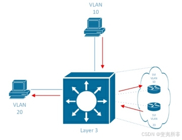
The third option for routing traffic between VLANs is to use a Layer 3 switch. This switch is capable of routing traffic from VLAN to VLAN internally, but it tends to be quite a bit more expensive than a Layer 2 switch. Older-model switches performed this routing via a separate routing blade that was inserted into the switch, but on modern switches this functionality is typically built into the switch. Cisco IOS switches handle this functionality via the use of a switch virtual interface (SVI). It shows a visual representation of the SVIs inside a Layer 3 switch as follows.
在 VLAN 之间路由流量的第三个选项是使用第 3 层交换机。此交换机能够在内部将流量从 VLAN 路由到 VLAN,但它往往比第 2 层交换机贵得多。旧型号交换机通过插入交换机的单独路由刀片执行此路由,但在现代交换机上,此功能通常内置在交换机中。Cisco IOS 交换机通过使用交换机虚拟接口 (SVI) 来处理此功能。它显示了第 3 层交换机内 SVI 的直观表示,如下所示。
*All VLANs internal to the Layer 3 switch*
第 3 层交换机内部的所有 VLAN

The Forwarding Path
转发路径
Here’s the next logical question: *How is traffic forwarded between VLANs?* For the answer, we’ll take a look at all three connectivity models discussed earlier.
这是下一个逻辑问题:VLAN 之间的流量如何转发?为了找到答案,我们将看看前面讨论的所有三种连接模型。
For option 1, let’s assume that two devices need to communicate—one is configured into VLAN 10, and the other is configured into VLAN 20. We’ll also assume that the Fa0/0 interface communicates with VLAN 10 traffic and the Fa0/1 interface communicates with VLAN 20 traffic. In this scenario, traffic from the VLAN 10 device will flow to the VLAN 20 device using the path shown in the following figure.
对于选项 1,我们假设两台设备需要通信 — 一台配置为 VLAN 10,另一台配置为 VLAN 20。我们还假设 Fa0/0 接口与 VLAN 10 流量通信,Fa0/1 接口与 VLAN 20 流量通信。在这种情况下,来自 VLAN 10 设备的流量将使用下图所示的路径流向 VLAN 20 设备。

Now let’s condense this layout a little and look at how the forwarding would work with a ROAS configuration. The Figure below, notice that the path looks very similar, but without needing an extra interface.
现在,我们稍微精简一下此布局,看看转发如何与 ROAS 配置配合使用。请注意,下图显示路径非常相似,但不需要额外的接口。

Finally, let’s look at how this design works with a Layer 3 switch. This layout is a bit different because it doesn’t need a separate routing device. In this case, the routing mechanism is built into the same switch, and SVIs route the traffic.
最后,让我们看看这种设计如何与第 3 层交换机配合使用。此布局略有不同,因为它不需要单独的路由设备。在这种情况下,路由机制内置于同一交换机中,SVI 路由流量。
Network Configuration
网络配置
Configuring any of the network options requires a good understanding of the concepts laid out in the previous sections. All of the following examples use four different VLANs: VLAN 10, VLAN 20, VLAN 30, and VLAN 40.
配置任何网络选项都需要很好地理解前面几节中介绍的概念。以下所有示例都使用四个不同的 VLAN:VLAN 10、VLAN 20、VLAN 30 和 VLAN 40。
The option 1 configuration requires the interfaces connected to the router to be configured into the correct VLANs. No special configuration is required on R1, as each interface would be configured like a standard LAN interface; the VLANs are invisible to R1 in this configuration.
选项 1 配置要求将连接到路由器的接口配置到正确的 VLAN 中。R1 上不需要特殊配置,因为每个接口的配置都类似于标准 LAN 接口;在此配置中,VLAN 对 R1 不可见。
Table 1 shows an example, using the diagram from the figure 1.
表 1 显示了一个示例,使用图 1 中的图表。

| Step | Action(s) | Command(s) |
|---|---|---|
| 1 | Enter global configuration mode. | SW1#configure terminal |
| 2 | Enter into VLAN configuration mode and/or create a VLAN (optional). | SW1(config)#vlan *vlan-id* |
| 3 | Configure a name for the VLAN (optional). | SW1(config-vlan)#name*name* |
| 4 | Enter into interface configuration mode for the first interface connecting to R1. | SW1(config-vlan)#interface fastethernet0/0 |
| 5 | Configure the ac |
 最低0.47元/天 解锁文章


 4513
4513

 被折叠的 条评论
为什么被折叠?
被折叠的 条评论
为什么被折叠?
 到【灌水乐园】发言


