


因最近公司需要,借此机会和大家一起学习AD9361
制作不易,记得三连哦,给我动力,持续更新!
纯Verilog配置AD9361工程文件下载:纯Verilog配置AD9361工程 提取码:g9jy
----------------------------------------------------------------------------------------
因为ADI官方,只提供了利用软件(SDK)和硬件平台(vivado)去配置AD936x,但是在一些工程中,这种方法很难去应用到实际的项目中,所以给大家介绍一个纯硬件配置AD936x的一个详细教程。因为是手把手教程,所以有些大佬不要嫌麻烦。同时后期会更新工程上的项目设计。废话不多说了,直接进入主题!和我一起学习神秘而又神奇AD936x吧!少年!
我用的是zedboard+ad9361,和我的硬件一样的伙伴,可以完全按照我的步骤进行,FPGA芯片为zynq7020的应该也可以。其余的根据自身芯片要求略微修改即可
在上一章节中,我们使用了 Analog Devices 公司提供的 AD936X Evaluation Software 软件生成了一个寄存器配置的脚本文件,命名为 trans.cfg,其中包含了许多寄存器的配置参数。然而.cfg格式的脚本只能在ADI提供的iio中使用,这个文件并不能直接在 FPGA 工程中调用,因为它的格式与我们需要的函数形式不匹配,需要对文件格式进行修改,将其转换为函数的形式。手动一行一行地修改显然是不可行的,因为配置文件非常庞大,修改起来非常费时费力。因此,我们需要找出配置文件的规律,并编写一个python程序来自动转换成我们需要的函数形式。这样,我们就可以在 FPGA 工程中直接调用这个函数,实现纯Verilog对寄存器参数的配置。让我们的工程更加简单,修改起来更加方便,可移植性也很强。加油吧!少年!
一、首先打开上一章生成的脚本文件
//************************************************************
// AD9361 R2 Auto Generated Initialization Script:  This script was
// generated using the AD9361 Customer software Version 2.1.4
//************************************************************
// Profile: Custom
// REFCLK_IN: 40.000 MHz

RESET_FPGA
RESET_DUT

BlockWrite	2,6	// Set ADI FPGA SPI to 20Mhz
SPIWrite	3DF,01	// Required for proper operation
ReadPartNumber
SPIWrite	2A6,0E	// Enable Master Bias
SPIWrite	2A8,0E	// Set Bandgap Trim
REFCLK_Scale	40.000000,1,2	// Sets local variables in script engine, user can ignore
SPIWrite	2AB,07	// Set RF PLL reflclk scale to REFCLK * 2
SPIWrite	2AC,FF	// Set RF PLL reflclk scale to REFCLK * 2
SPIWrite	009,17	// Enable Clocks
WAIT	20	// waits 20 ms
//************************************************************
// Set BBPLL Frequency: 1280.000000
//************************************************************
SPIWrite	045,00	// Set BBPLL reflclk scale to REFCLK /1
SPIWrite	046,05	// Set BBPLL Loop Filter Charge Pump current
SPIWrite	048,E8	// Set BBPLL Loop Filter C1, R1
SPIWrite	049,5B	// Set BBPLL Loop Filter R2, C2, C1
SPIWrite	04A,35	// Set BBPLL Loop Filter C3,R2
SPIWrite	04B,E0	// Allow calibration to occur and set cal count to 1024 for max accuracy
SPIWrite	04E,10	// Set calibration clock to REFCLK/4 for more accuracy
SPIWrite	043,00	// BBPLL Freq Word (Fractional[7:0])
SPIWrite	042,00	// BBPLL Freq Word (Fractional[15:8])
SPIWrite	041,00	// BBPLL Freq Word (Fractional[23:16])
SPIWrite	044,20	// BBPLL Freq Word (Integer[7:0])
SPIWrite	03F,05	// Start BBPLL Calibration
SPIWrite	03F,01	// Clear BBPLL start calibration bit
SPIWrite	04C,86	// Increase BBPLL KV and phase margin
SPIWrite	04D,01	// Increase BBPLL KV and phase margin
SPIWrite	04D,05	// Increase BBPLL KV and phase margin
WAIT_CALDONE	BBPLL,2000	// Wait for BBPLL to lock, Timeout 2sec, Max BBPLL VCO Cal Time: 345.600 us (Done when 0x05E[7]==1)
**
**
**
字
数
太
多
**
此
处
省
略
**
**
**
SPIWrite	073,28
SPIWrite	074,00
SPIWrite	075,28
SPIWrite	076,00
//************************************************************
// Setup RSSI and Power Measurement Duration Registers
//************************************************************
SPIWrite	150,0B	// RSSI Measurement Duration 0, 1
SPIWrite	151,00	// RSSI Measurement Duration 2, 3
SPIWrite	152,FF	// RSSI Weighted Multiplier 0
SPIWrite	153,00	// RSSI Weighted Multiplier 1
SPIWrite	154,00	// RSSI Weighted Multiplier 2
SPIWrite	155,00	// RSSI Weighted Multiplier 3
SPIWrite	156,00	// RSSI Delay
SPIWrite	157,00	// RSSI Wait
SPIWrite	158,0D	// RSSI Mode Select
SPIWrite	15C,69	// Power Measurement Duration
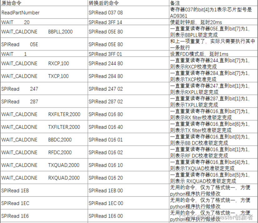
我们发现其中包含了 SPIWrite 命令和少量的 SPIRead 命令,以及其他命令包括 RESET_FPGA、RESET_DUT、BlockWrite、ReadPartNumber、WAIT、WAIT_CALDONE 等。其中,RESET_FPGA 和 RESET_DUT 是用来复位 FPGA 和 AD9361 的操作,我们可以直接在初始化前进行复位。BlockWrite 命令是用来确定 SPI 时钟频率的,我们可以忽略它,因为 SPI 时钟频率由 FPGA 的代码确定。ReadPartNumber 是指读取寄存器 037 的值,因此可以转换为 SPIRead 命令,或者直接丢掉这行命令,对初始化没有影响。WAIT_CALDONE 是读取某个确定的寄存器,读回某个值后继续执行下一步的操作,因此我们也可以将其转换为 SPIRead 命令。而 WAIT 命令也可以转换为某个特定的 SPIRead 命令,代码在执行到这行命令时,固定延时等待就好了。
综上所述,整个配置脚本可以转换为 SPIWrite 和 SPIRead 的组合。因此,我们可以定义一个 17 位的数,其中最高位 bit[16] 表示读或写,1 表示写,0 表示读。接下来 bit[15:8] 表示要读写的地址,最后 8 位根据命令不同,填入不同的值。具体来说,对于 SPIWrite 命令,最后 8 位表示要写入的数据;对于 SPIRead 命令,最后 8 位可以填任意值,因为它们将被忽略。通过这种方式,我们可以将配置脚本转换为一系列的 SPIWrite 和 SPIRead 命令,从而实现对寄存器参数的配置。最终通过我自己写的脚本,转换成我们工程上可以直接使用的Verilog程序。
二、python转化脚本程序
根据xilinx官方文档上面的说明,可以设计一个python转化代码程序,
我给大家推荐两种方法:
(1)有python基础的同学(有基础的)(源文件在最后 ↓)
可以直接搭建python环境,打开电脑的cmd界面,并且定位到.cfg文件的路径下面(同时.py的文件也在这个文件夹下)

执行下面的一行指令,然后回车,即可导出Verilog配置脚本程序。
trans_verilog.py trans.cfg ad9361_lut.v(2)没有python基础的同学(小白推荐)
因为这次设计主要是为了给小白手把手讲解用纯Verilog配置AD9361,所以我联合我同事给小白们专门写了一个exe程序,直接一键就可以把.cfg脚本文件转化为Verilog脚本程序,加快AD936x的配置过程。
脚本文件转化为Verilog脚本exe文件:脚本文件转化为Verilog代码exe程序下载
双击打开转换软件ad9361-trans.exe

打开软件后,选择上一章生成的脚本文件

然后点击打开,即可得到可在vivado工程中使用的Verilog脚本文件ad9361_lut.v。

查看导出后的ad9361_lut.v文件:
function [18:0] ad9361_lut;
input [12:0] index;
  begin
    case(index)
      //************************************************************
      // AD9361 R2 Auto Generated Initialization Script:  This script was
      // generated using the AD9361 Customer software Version 2.1.3
      //************************************************************
      // Profile: Custom
      // REFCLK_IN: 40.000 MHz

      //RESET_FPGA
      //RESET_DUT

      //BlockWrite	2,6	// Set ADI FPGA SPI to 20Mhz
      13'd0:ad9361_lut={1'b1,10'h3DF,8'h01};	// Required for proper operation
      13'd1:ad9361_lut={1'b0,10'h037,8'h08};//ReadPartNumber
      13'd2:ad9361_lut={1'b1,10'h2A6,8'h0E};	// Enable Master Bias
      13'd3:ad9361_lut={1'b1,10'h2A8,8'h0E};	// Set Bandgap Trim
      //REFCLK_Scale	40.000000,1,2	// Sets local variables in script engine, user can ignore
      13'd4:ad9361_lut={1'b1,10'h292,8'h08};	// Set DCXO Coarse Tune[5:0].  Coarse and Fine nominal values used with eval system.  Other nominal values may be needed in a customer system
      13'd5:ad9361_lut={1'b1,10'h293,8'h80};	// Set DCXO Fine Tune [12:5]
      13'd6:ad9361_lut={1'b1,10'h294,8'h00};	// Set DCXO Fine Tune [4:0]
      13'd7:ad9361_lut={1'b1,10'h2AB,8'h07};	// Set RF PLL reflclk scale to REFCLK * 2
      13'd8:ad9361_lut={1'b1,10'h2AC,8'hFF};	// Set RF PLL reflclk scale to REFCLK * 2
      13'd9:ad9361_lut={1'b1,10'h009,8'h07};	// Enable Clocks
      13'd10:ad9361_lut={1'b0,10'h3FF,8'h14};// waits 20 ms

      //************************************************************
      // Set BBPLL Frequency: 1280.000000
      //************************************************************
      13'd11:ad9361_lut={1'b1,10'h045,8'h00};	// Set BBPLL reflclk scale to REFCLK /1
      13'd12:ad9361_lut={1'b1,10'h046,8'h05};	// Set BBPLL Loop Filter Charge Pump current
      13'd13:ad9361_lut={1'b1,10'h048,8'hE8};	// Set BBPLL Loop Filter C1, R1
      13'd14:ad9361_lut={1'b1,10'h049,8'h5B};	// Set BBPLL Loop Filter R2, C2, C1
      13'd15:ad9361_lut={1'b1,10'h04A,8'h35};	// Set BBPLL Loop Filter C3,R2
      13'd16:ad9361_lut={1'b1,10'h04B,8'hE0};	// Allow calibration to occur and set cal count to 1024 for max accuracy
      13'd17:ad9361_lut={1'b1,10'h04E,8'h10};	// Set calibration clock to REFCLK/4 for more accuracy
      13'd18:ad9361_lut={1'b1,10'h043,8'h00};	// BBPLL Freq Word (Fractional[7:0])
      13'd19:ad9361_lut={1'b1,10'h042,8'h00};	// BBPLL Freq Word (Fractional[15:8])
      13'd20:ad9361_lut={1'b1,10'h041,8'h00};	// BBPLL Freq Word (Fractional[23:16])
      13'd21:ad9361_lut={1'b1,10'h044,8'h20};	// BBPLL Freq Word (Integer[7:0])
      13'd22:ad9361_lut={1'b1,10'h03F,8'h05};	// Start BBPLL Calibration
      13'd23:ad9361_lut={1'b1,10'h03F,8'h01};	// Clear BBPLL start calibration bit
      13'd24:ad9361_lut={1'b1,10'h04C,8'h86};	// Increase BBPLL KV and phase margin
      13'd25:ad9361_lut={1'b1,10'h04D,8'h01};	// Increase BBPLL KV and phase margin
      13'd26:ad9361_lut={1'b1,10'h04D,8'h05};	// Increase BBPLL KV and phase margin

/*

省
略
多
行

*/

      // Setup RSSI and Power Measurement Duration Registers
      //************************************************************
      13'd2564:ad9361_lut={1'b1,10'h150,8'h0B};	// RSSI Measurement Duration 0, 1
      13'd2565:ad9361_lut={1'b1,10'h151,8'h00};	// RSSI Measurement Duration 2, 3
      13'd2566:ad9361_lut={1'b1,10'h152,8'hFF};	// RSSI Weighted Multiplier 0
      13'd2567:ad9361_lut={1'b1,10'h153,8'h00};	// RSSI Weighted Multiplier 1
      13'd2568:ad9361_lut={1'b1,10'h154,8'h00};	// RSSI Weighted Multiplier 2
      13'd2569:ad9361_lut={1'b1,10'h155,8'h00};	// RSSI Weighted Multiplier 3
      13'd2570:ad9361_lut={1'b1,10'h156,8'h00};	// RSSI Delay
      13'd2571:ad9361_lut={1'b1,10'h157,8'h00};	// RSSI Wait
      13'd2572:ad9361_lut={1'b1,10'h158,8'h0D};	// RSSI Mode Select
      13'd2573:ad9361_lut={1'b1,10'h15C,8'h69};	// Power Measurement Duration

      //************************************************************
      //Manually add:Force RX and TX on
      //************************************************************
      13'd2574:ad9361_lut={1'b0,10'h3FF,8'h14};	// delay
      13'd2575:ad9361_lut={1'b1,10'h014,8'h23};	// Set FDD
      13'd2576:ad9361_lut={1'b1,10'h015,8'h84};	// Set FDD  Independent
      13'd2577:ad9361_lut={1'b0,10'h3FF,8'hFF};	// end of command
    endcase
  end
endfunction
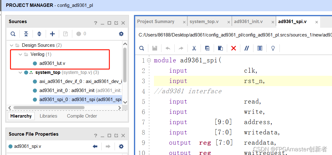
三、加入的vivado工程
然后把文件加入到vivado工程,通过SPI去读脚本中的寄存器配置,进行对AD9361的一些列配置,并可以进行后续的开发,大大减少了开发时间和工作成本。
脚本文件转化Verilog的python脚本源文件:
#!/usr/bin/perl

# Version 1.0

use strict;
use warnings;

# Obtain input file path and output file path
my $input_file = shift @ARGV;
my $output_file = shift @ARGV;

# Check input parameters
die "Please enter the input file path and output file path.\n" unless defined $input_file && defined $output_file;

# Open input file for reading
open(my $input_fh, "<", $input_file) or die "Unable to open input file: $!";

# Open output file for writing
open(my $output_fh, ">", $output_file) or die "Unable to open input file: $!";

# Initialize Counter
my $count = 0;

# Read input files line by line
while (my $line = <$input_fh>) {
    chomp $line;

    # SPI interface configuration
##
##
    省
    略
    多
    行
##
##
    # replace SPIRead
    elsif ($line =~ /SPIRead\s+(\w+)/) {
        my $cmd = $1;

        my $replacement = "13'd$count: ad9361_cmd_data = {1'b0, 10'h$cmd, 8'h00};";

        print $output_fh "$replacement\n";

        # Counter increment
        $count++;
    }
}

# close a file handle
close($input_fh);
close($output_fh);

print "Replacement completed. Output file is $output_file\n";下一章将讲解,如何使用SPI去调用这个脚本文件,并配置到AD9361,还会讲解对这个配置进行下板验证和仿真。


 2587
2587


 被折叠的 条评论
为什么被折叠?
被折叠的 条评论
为什么被折叠?
 到【灌水乐园】发言


