


负载均衡的企业网络
情景描述:
本公司原来采用的是单核心网络,具有单点故障的风险。为了保障网络的稳定性、可用性,先对公司的网络进行改造,要求改造后的网络为双核心的稳定结构。
任务分析:
单核心网络已经无法满足本公司的需求,因此采用双核心的冗余网络,这样可以保障公司网络的稳定性。利用MSTP协议和VRRP协议可以提高可靠性,并且在实现冗余备份的同时,可以实现负载均衡。在MSTP协议中创建多个生成树实例,可以实现VLAN之间的负载均衡,不同VLAN的流量按照不同的路径转发。在VRRP协议中创建多个备份组,为各个备份组知道那个不同的Master和Backup,可以实现虚拟路由的负载均衡。
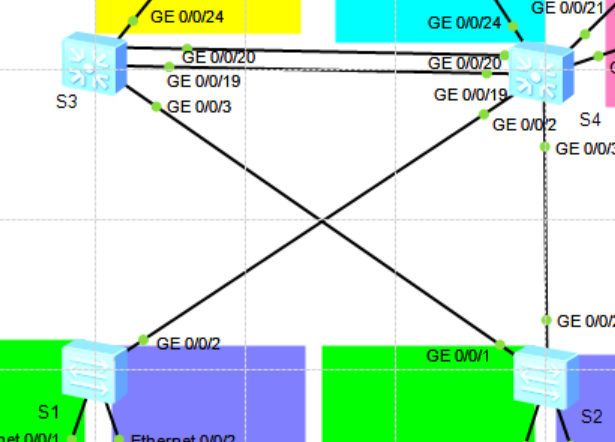
拓扑图如下:

分析:此次实验考察VLAN、Trunk、VLANIF、链路聚合、交换机DHCP服务配置、静态路由等知识。
VLAN地址规划如下:
| VLAN ID | VLANIF地址 | 包含设备 | 备注 |
|---|---|---|---|
| 10 | 192.168.10.254/24 | PC1、PC3 | 计算机接入网络 |
| 20 | 192.168.20.254/24 | PC2、PC4 | 计算机接入网络 |
| 100 | 192.1638.100.254/24 | HTTP、FTP | 服务器网段 |
| 110 | 192.168.110.254/24 | R1:GE0/0/1 | 与R1通信 |
| 120 | 192.168.120.254/24 | R1:GE0/0/2 | 与R1通信 |
实验要求:
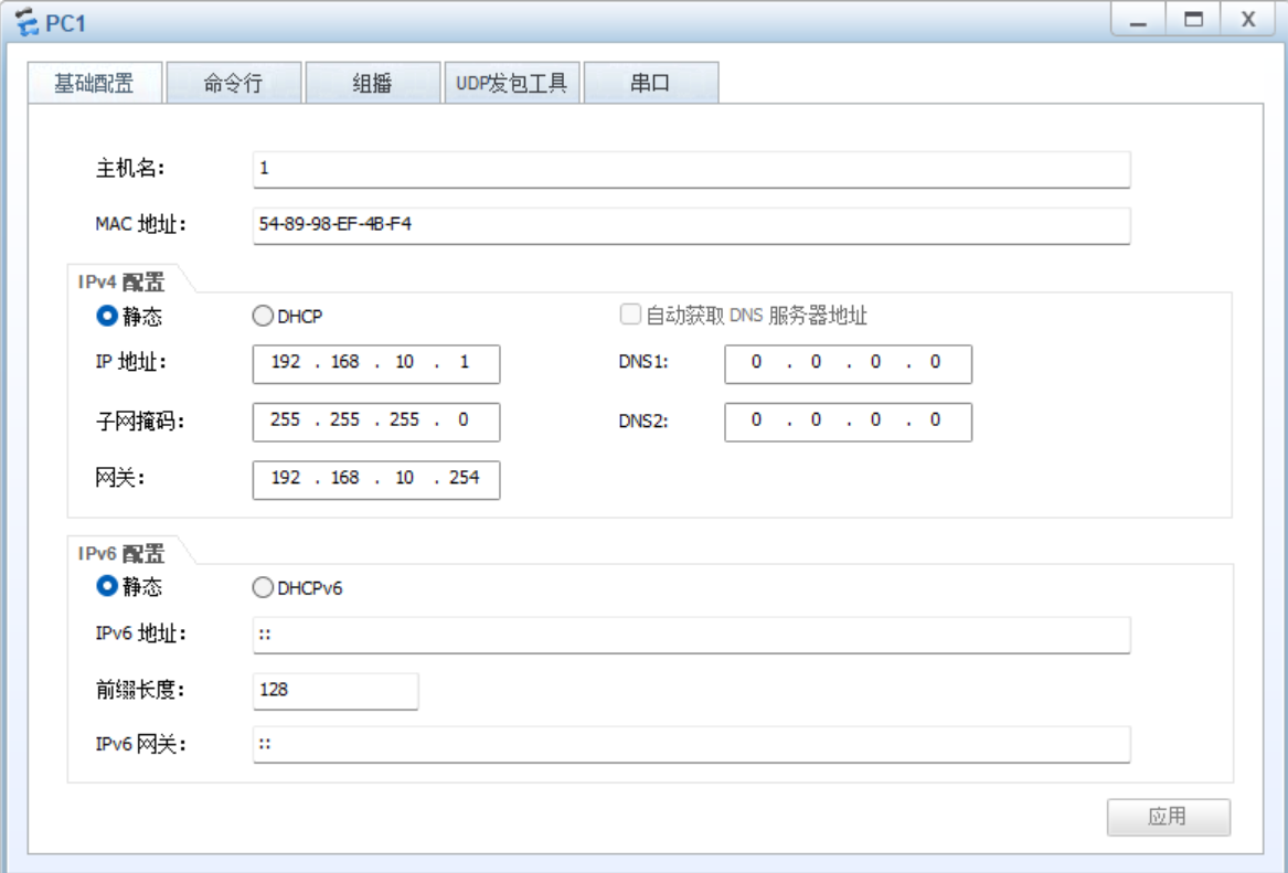
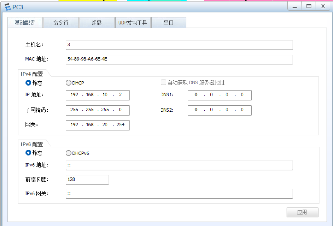
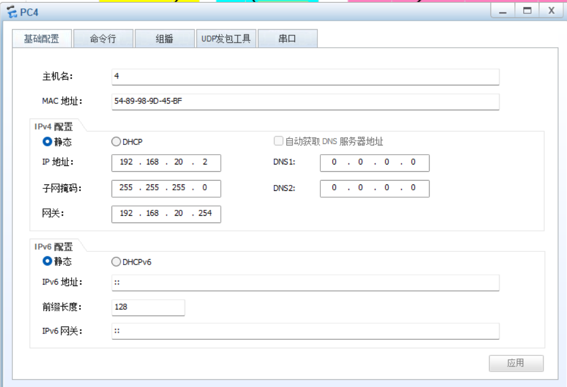
1、根据网络拓扑结构添加相应设备,并使用正确的线缆连接所有设备,表明所连接的接口名称。2、设置PC1、PC27PC3、PC4、HTTP、FTP的IP地址、子网掩码与网关。
3、完成VLANIF地址的配置。为了保证所有连路都能够被充分利用,是流量能够被分担,需要在S1和S2上完成MSTP的配置。
4、为了保障主机与外界通信的可靠性,需要在S3和S4上完成VRRP协议的配置。
5、在S3、S4和R1上配置静态路由,保障内网用户可以相互通信。
6、在HTTP上配置HTTP服务,完成Web站点部署。
7、在R1上配置Easy IP,使内网用户可以正常访问外网。
8、在R1上配置NAT Server,将HTTP服务器的IP地址映射到公有IP地址200.200.200.2/30上。
配置:
交换机的配置
S1的基本配置
<Huawei>sys
[Huawei]undo in e
[Huawei]sys S1
[S1]vlan ba 10 20
[S1]int e0/0/1
[S1-Ethernet0/0/1]port link-type  access
[S1-Ethernet0/0/1]port default  vlan 10
[S1-Ethernet0/0/1]int e0/0/2
[S1-Ethernet0/0/2]port  link-type  access
[S1-Ethernet0/0/2]port default  vlan 20
[S1-Ethernet0/0/2]int g0/0/1
[S1-GigabitEthernet0/0/1]port link-type  trunk
[S1-GigabitEthernet0/0/1]port trunk allow-pass  vlan all
[S1-GigabitEthernet0/0/1]int g0/0/2
[S1-GigabitEthernet0/0/2]port link-type  trunk
[S1-GigabitEthernet0/0/2]port trunk allow-pass  vlan  all
[S1-GigabitEthernet0/0/2]q
[S1]
S2的基本配置
<Huawei>sys
[Huawei]undo in e
[Huawei]sys S2
[S2]vlan ba 10 20
[S2]int g0/0/1
[S2-GigabitEthernet0/0/1]port link-type  trunk
[S2-GigabitEthernet0/0/1]port trunk allow-pass  vlan all
[S2-GigabitEthernet0/0/1]int g0/0/2
[S2-GigabitEthernet0/0/2]port link-t trunk
[S2-GigabitEthernet0/0/2]port trunk allow-pass  vlan all
[S2-GigabitEthernet0/0/2]int e0/0/1
[S2-Ethernet0/0/1]port link-type  access
[S2-Ethernet0/0/1]port default  vlan 10
[S2-Ethernet0/0/1]int e0/0/2
[S2-Ethernet0/0/2]port link-type  access
[S2-Ethernet0/0/2]port default  vlan 20
[S2-Ethernet0/0/2]q
[S2]
S3的基本配置
<Huawei>sys
[Huawei]
[Huawei]undo in e
[Huawei]sys S3
[S3]vlan ba 10 20 110
[S3]int g0/0/3
[S3-GigabitEthernet0/0/3]port link-type  trunk
[S3-GigabitEthernet0/0/3]port trunk allow-pass vlan all
[S3-GigabitEthernet0/0/1]int g0/0/2
[S3-GigabitEthernet0/0/2]port link-type  trunk
[S3-GigabitEthernet0/0/2]port trunk allow-pass  vlan all
[S3-GigabitEthernet0/0/2]q
[S3]int Eth-Trunk  1
[S3-Eth-Trunk1]trunkport g0/0/19
[S3-Eth-Trunk1]trunkport g0/0/20
[S3-Eth-Trunk1]port link-type trunk
[S3-Eth-Trunk1]port trunk allow-pass  vlan all
[S3-Eth-Trunk1]q
[S3]int g0/0/24
[S3-GigabitEthernet0/0/24]port link-type  access
[S3-GigabitEthernet0/0/24]port default  vlan 110
[S3-GigabitEthernet0/0/24]q
[S3]int vlan 110
[S3-Vlanif110]ip add 192.168.110.254 24
[S3-Vlanif110]int vlan 10
[S3-Vlanif10]ip add 192.168.10.253 24
[S3-Vlanif10]int vlan 20
[S3-Vlanif20]ip add 192.168.20.253 24
[S3-Vlanif20]
S4的基本配置
<Huawei>sys
[Huawei]undo in e
Info: Information center is disabled.
[Huawei]sys S4
[S4]vlan ba 10 20 100 120
[S4]int g0/0/2
[S4-GigabitEthernet0/0/2]port link-type  trunk
[S4-GigabitEthernet0/0/2]port trunk allow-pass  vlan all
[S4-GigabitEthernet0/0/2]int g0/0/3
[S4-GigabitEthernet0/0/3]port link-type  trunk
[S4-GigabitEthernet0/0/3]port trunk allow-pass vlan all
[S4-GigabitEthernet0/0/3]q
[S4]int Eth-Trunk 1
[S4-Eth-Trunk1]trunkport g0/0/20
[S4-Eth-Trunk1]trunkport g0/0/19
[S4-Eth-Trunk1]port link-type trunk
[S4-Eth-Trunk1]port trunk allow-pass  vlan all
[S4-Eth-Trunk1]q
[S4]int g0/0/21
[S4-GigabitEthernet0/0/21]port link-type  access
[S4-GigabitEthernet0/0/21]port default  vlan 100
[S4-GigabitEthernet0/0/21]int g0/0/22
[S4-GigabitEthernet0/0/22]port link-type access
[S4-GigabitEthernet0/0/22]port default  vlan 100
[S4]int g0/0/24
[S4-GigabitEthernet0/0/24]port link-type  access
[S4-GigabitEthernet0/0/24]port default  vlan 120
[S4-GigabitEthernet0/0/24]q
[S4]int vlan 120
[S4-Vlanif120]ip add 192.168.120.254 24
[S4-Vlanif120]int vlan 10
[S4-Vlanif10]ip add 192.168.10.252 24
[S4-Vlanif10]int vlan 20
[S4-Vlanif20]ip add 192.168.20.252  24
[S4-Vlanif20]int vlan 100
[S4-Vlanif100]ip add 192.168.100.254 24
[S4-Vlanif100]q
[S4]
路由器的配置
R1的基本配置
<Huawei>sys
[Huawei]undo in e
[Huawei]sys R1
[R1]int g0/0/1
[R1-GigabitEthernet0/0/1]ip add 192.168.110.1 24
[R1-GigabitEthernet0/0/1]int g0/0/2
[R1-GigabitEthernet0/0/2]ip add 192.168.120.1 24
[R1-GigabitEthernet0/0/2]q
[R1]int s
[R1]int Serial 4/0/0
[R1-Serial4/0/0]i add 200.200.200.2 30
[R1-Serial4/0/0]q
[R1]q
<R1>save
  The current configuration will be written to the device.
  Are you sure to continue? (y/n)[n]:y
  It will take several minutes to save configuration file, please wait........
  Configuration file had been saved successfully
  Note: The configuration file will take effect after being activated
<R1>
R2的基本配置
<Huawei>sys
[Huawei]undo in e
[Huawei]sys R2
[R2]int g0/0/0
[R2-GigabitEthernet0/0/0]ip add 200.200.200.5 30
[R2-GigabitEthernet0/0/0]q
[R2]int Serial 4/0/0
[R2-Serial4/0/0]ip add 200.200.200.1 30
[R2-Serial4/0/0]q
[R2]q
<R2>save
  The current configuration will be written to the device.
  Are you sure to continue? (y/n)[n]:y
  It will take several minutes to save configuration file, please wait.......
  Configuration file had been saved successfully
  Note: The configuration file will take effect after being activated
<R2>
MSTP的配置
S1的MSTP配置
[S1]stp mode mstp
[S1]stp region-configuration
[S1-mst-region]region-name huawei
[S1-mst-region]instance  1 vlan 10
[S1-mst-region]instance  2 vlan  20
[S1-mst-region]active  region-configuration
[S1-mst-region]q
[S1]q
<S1>save
The current configuration will be written to the device.
Are you sure to continue?[Y/N]y
Info: Please input the file name ( *.cfg, *.zip ) [vrpcfg.zip]:
Now saving the current configuration to the slot 0.
Save the configuration successfully.
<S1>
S2的MSTP配置
[S2]stp mode mstp
[S2]stp region-configuration
[S2-mst-region]region-name huawei
[S2-mst-region]instance  1 vlan 10
[S2-mst-region]instance  2 vlan 20
[S2-mst-region]active  region-configuration
[S2-mst-region]q
[S2]q
<S2>save
The current configuration will be written to the device.
Are you sure to continue?[Y/N]y
Info: Please input the file name ( *.cfg, *.zip ) [vrpcfg.zip]:
Now saving the current configuration to the slot 0.
Save the configuration successfully.
<S2>
S3的MSTP配置
[S3]stp mode mstp
[S3]stp region-configuration
[S3-mst-region]region-name huawei
[S3-mst-region]instance 1 vlan 10
[S3-mst-region]instance  2 vlan  20
[S3-mst-region]active  region-configuration
[S3-mst-region]q
[S3]stp instance 1 root  primary
[S3]stp instance 2 root  secondary
[S3]q
<S3>save
The current configuration will be written to the device.
Are you sure to continue?[Y/N]y
Info: Please input the file name ( *.cfg, *.zip ) [vrpcfg.zip]:
Now saving the current configuration to the slot 0.
Save the configuration successfully.
<S3>
S4的MSTP配置
[S4]stp mode mstp
[S4]stp region-configuration
[S4-mst-region]region-name huawei
[S4-mst-region]instance  1 vlan 10
[S4-mst-region]instance 2 vlan 10
[S4-mst-region]active  region-configuration
[S4-mst-region]q
[S4]stp instance 1 root secondary
[S4]stp instance  2 root primary
[S4]q
<S4>save
The current configuration will be written to the device.
Are you sure to continue?[Y/N]y
Info: Please input the file name ( *.cfg, *.zip ) [vrpcfg.zip]:
Now saving the current configuration to the slot 0.
Save the configuration successfully.
<S4>
VRRP协议的配置
S3的VRRP配置
[S3]int vlan 10
[S3-Vlanif10]vrrp vrid  10 virtual-ip 192.168.10.254
//设置虚拟网关
[S3-Vlanif10]vrrp vrid  10 priority 120
//调整优先级为120,并使其成为Master
[S3-Vlanif10]vrrp vrid  10 track interface g0/0/24 reduced 50
//监视上行接口g0/0/24,当此接口断掉时,裁剪优先级50,让出Master
[S3-Vlanif10]int vlan 20
[S3-Vlanif20]vrrp vrid 20 virtual-ip 192.168.20.254
[S3-Vlanif20]vrrp vrid  20 track interface g0/0/24 reduced  50
[S3-Vlanif20]q
[S3]
S4的VRRP配置
[S4]int vlan 20
[S4-Vlanif20]vrrp vrid 20 virtual-ip 192.168.20.254
[S4-Vlanif20]vrrp vrid 20 priority 120
[S4-Vlanif20]vrrp vrid  20 track  interface  g0/0/24 reduced  50
[S4-Vlanif20]int vlan 10
[S4-Vlanif10]vrrp vrid  10 virtual-ip 192.168.10.254
[S4-Vlanif10]vrrp vrid  10 track  interface g0/0/24 reduced  50
[S4-Vlanif10]q
[S4]
路由协议的配置
S3的路由协议配置
[S3]ip route-static  0.0.0.0 0 192.168.110.1
[S3]ip route-static 192.168.100.0 24 192.168.10.252
[S3]q
<S3>save
The current configuration will be written to the device.
Are you sure to continue?[Y/N]y
Now saving the current configuration to the slot 0.
Save the configuration successfully.
<S3>
S4的路由协议配置
[S4]ip route-static 0.0.0.0 0 192.168.120.1
[S4]q
<S4>save
The current configuration will be written to the device.
Are you sure to continue?[Y/N]y
Now saving the current configuration to the slot 0.
Save the configuration successfully.
<S4>
R1的路由协议配置
[R1]ip route-static 0.0.0.0 0 200.200.200.1
[R1]ip route-static 192.168.0.0 16 192.168.120.254
[R1]ip route-static 192.168.0.0 16 192.168.110.254 preference 100
[R1]q
<R1>save
  The current configuration will be written to the device.
  Are you sure to continue? (y/n)[n]:y
  It will take several minutes to save configuration file, please wait.......
  Configuration file had been saved successfully
  Note: The configuration file will take effect after being activated
<R1>
计算机的IP地址等信息的配置
PC1:
PC2:

PC3:
PC4:
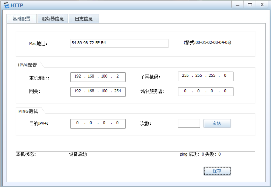
HTTP、FTP、Clicent1的配置
IP地址的设置
HTTP:
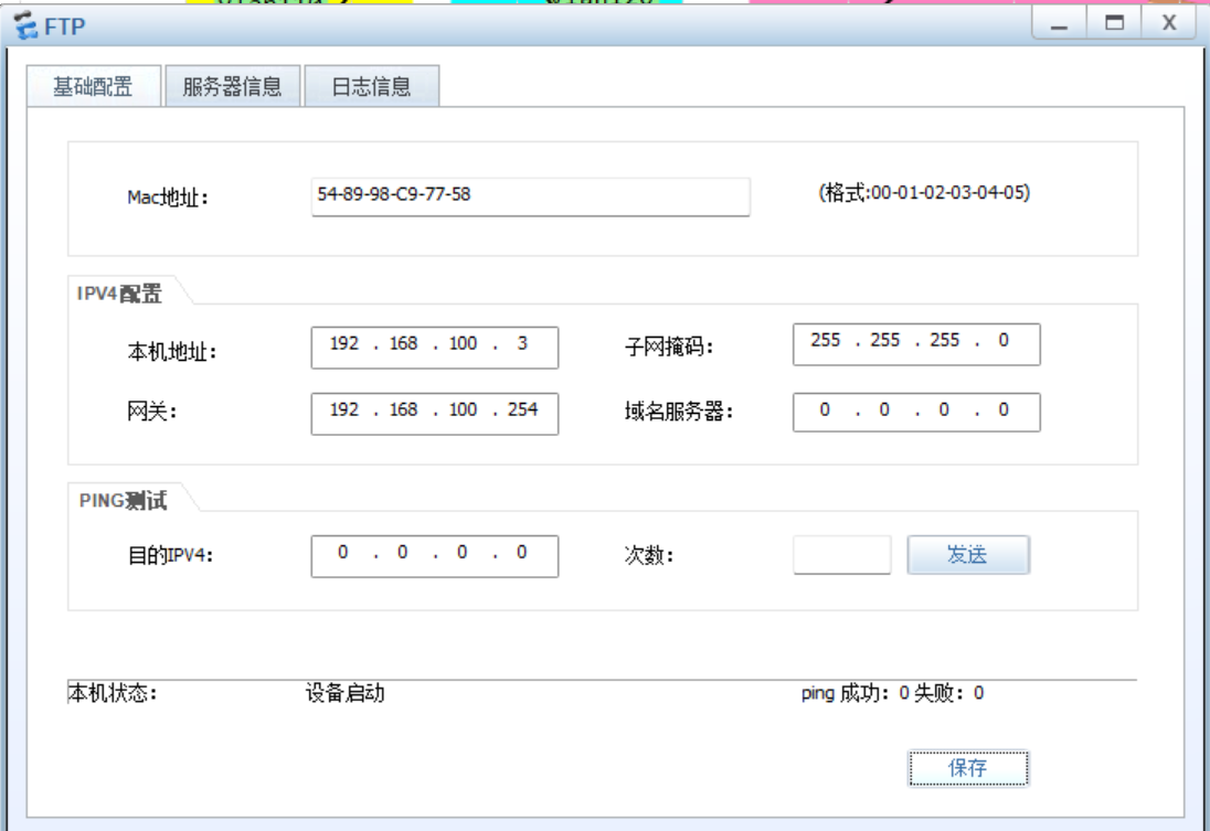
FTP:
Clicent1:

服务器信息设置
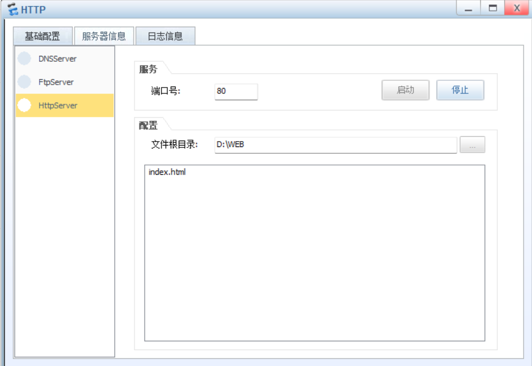
在HTTP上单击鼠标右键,在弹出的快捷菜单中选择“服务器信息”命令,在打开的窗口中切换到“服务器信息”选项卡中,选中“HTTPServer”单选按钮,并在“配置”选项组中进行文件根目录的添加,这里选择的是“D:\WEB\inde.html”,最后单击启动按钮。
NAT协议的配置
这里采用Easy IP方式实现内网到外网的映射
[R1]acl 2000
[R1-acl-basic-2000]rule  5 permit  source  192.168.0.0 0.0.255.255
[R1-acl-basic-2000]q
[R1]int Serial 4/0/0
[R1-Serial4/0/0]nat outbound  2000
[R1-Serial4/0/0]nat server protocol  tcp  global  current-interface  www inside
 192.168.100.2 www
Warning:The port 80 is well-known port. If you continue it may cause function fa
ilure.
Are you sure to continue?[Y/N]:y
[R1-Serial4/0/0]q
[R1]q
<R1>save
  The current configuration will be written to the device.
  Are you sure to continue? (y/n)[n]:y
  It will take several minutes to save configuration file, please wait.......
  Configuration file had been saved successfully
  Note: The configuration file will take effect after being activated
<R1>
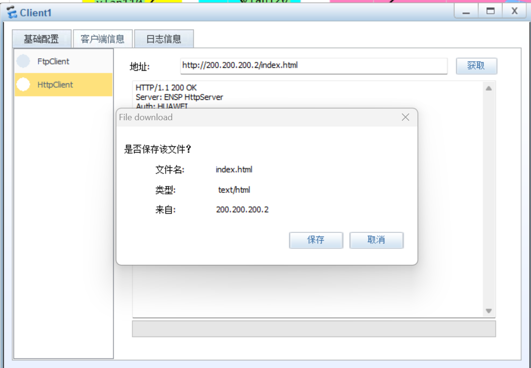
Clicent1访问HTTP Server
切换到Clicent1的“客户端信息”选项卡,选中“HTTPServer”单选按钮,然后在“地址”文本框中输入“http://200.200.200.2/index.html”,最后单击“获取”按钮。
测试
使用ping命令测试PC1到PC4的连通性
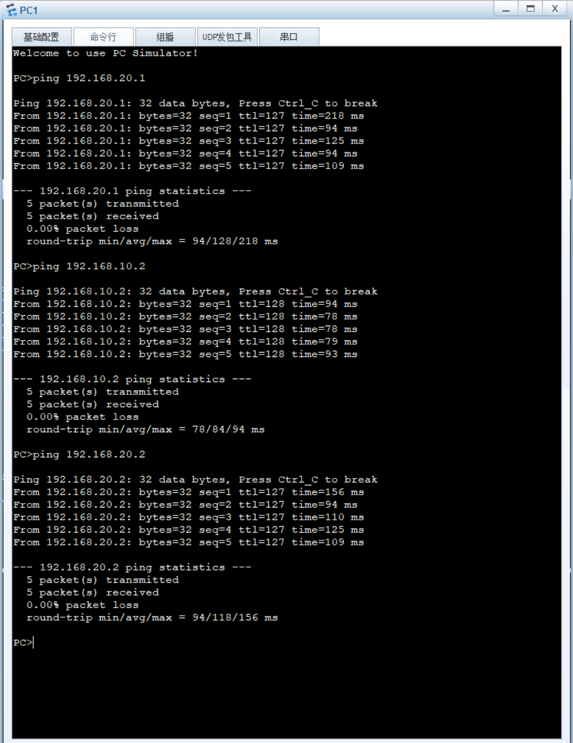
使用ping命令测试PC1到FTP服务器的连通性
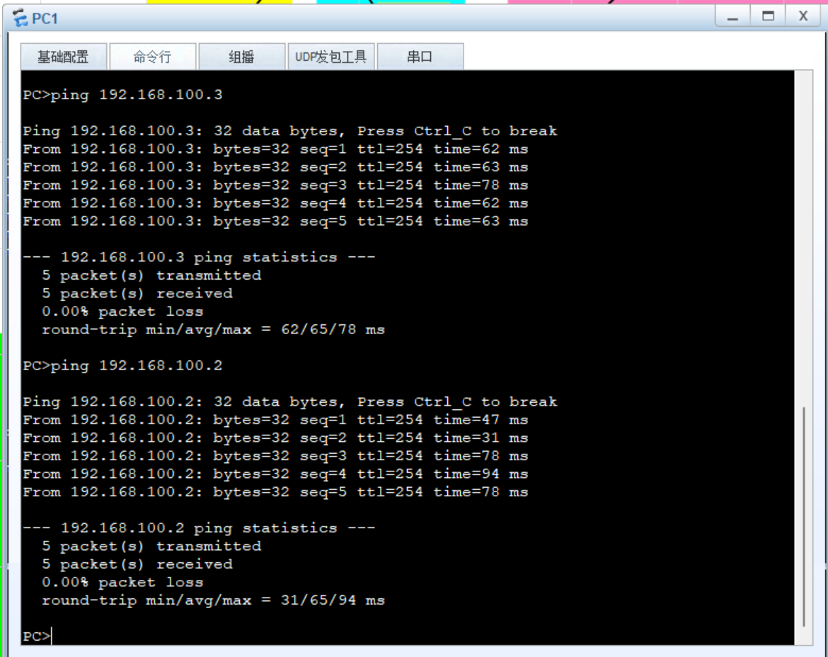
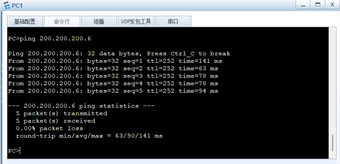
使用ping命令测试PC1到Clicent1服务器的连通性
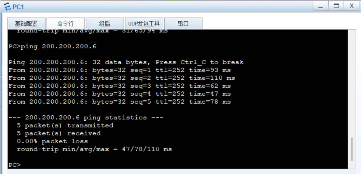
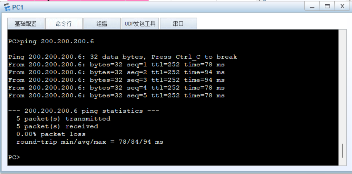
断掉S1和S3之间的连接线,测试PC1是否可以ping通Clicent1
断掉S3和R1之间的连接线,测试PC1是否可以ping通Clicent1

使用Clicent1中的“HTTPServer”访问“http://200.200.200.2/index.html”,测试是否可以浏览网页


 被折叠的 条评论
为什么被折叠?
被折叠的 条评论
为什么被折叠?
 到【灌水乐园】发言


